display ISUZU KB P190 2007 Workshop Repair Manual
[x] Cancel search | Manufacturer: ISUZU, Model Year: 2007, Model line: KB P190, Model: ISUZU KB P190 2007Pages: 6020, PDF Size: 70.23 MB
Page 3545 of 6020
Engine Management – V6 – Service Operations Page 6C1-3–21
NOTE
When Tech 2 requests programming approval,
obtain TIS approval.
3 W hen Tech 2 displays Enter Security Code, enter the security code, press the Enter key and then the Okay soft
key.
The engine will not start after the ECM has
been reset.
4 W hen Tech 2 displays Do you really want to Reset? , press the Reset soft key.
5 W hen Tech 2 displays Stop Engine - Turn Off Ignition , turn the ignition off and press the Confirm soft key.
6 W hen Tech 2 displays Turn Ignition On, turn the ignition on and press the Confirm soft key.
7 W hen Tech 2 displays Reset Completed Successfully , press the Confirm soft key to return to the Tech 2
Programming screen.
2.8 Engine Control Module Bracket Assembly
Remove
1 Remove the engine control module (ECM), refer to 2.7 Engine Control Module.
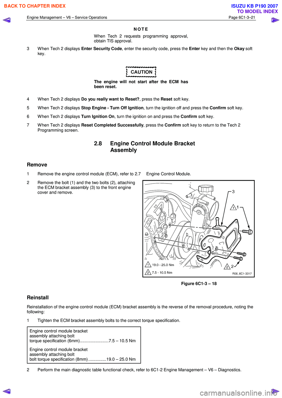
2 Remove the bolt (1) and the two bolts (2), attaching the ECM bracket assembly (3) to the front engine
cover and remove.
Figure 6C1-3 – 18
Reinstall
Reinstallation of the engine control module (ECM) bracket assembly is the reverse of the removal procedure, noting the
following:
1 Tighten the ECM bracket assembly bolts to the correct torque specification.
Engine control module bracket
assembly attaching bolt
torque specification (6mm)........................7.5 – 10.5 Nm
Engine control module bracket
assembly attaching bolt
bolt torque specification (8mm) ...............19.0 – 25.0 Nm
2 Perform the main diagnostic table functional check, refer to 6C1-2 Engine Management – V6 – Diagnostics.
BACK TO CHAPTER INDEX
TO MODEL INDEX
ISUZU KB P190 2007
Page 3593 of 6020
Charging System – V6 Page 6D1-1-6
Alternator Warning
NOTE
All generator faults are displayed as
Check Alternator W arning on the instrument
cluster MFD, refer to 8A Electrical Body and
Chassis.
The ECM monitors the voltage on connector E-60 pin 21 and pin 43.
The voltage at the generator connector E-4 pin 2 will remain low when a fault condition is detected in the generator or
associated external circuits. The voltage remains low (while the ignition switch is on) until the fault is repaired.
NOTE
For more information on the alternator warning
refer to 8A Electrical Body and Chassis.
Fault conditions include the following:
• open circuit or excessive voltage drop in circuit 1,
• open circuit in the generator phase connection,
• overcharging conditions,
• short circuit in the regulator output stage,
• open circuit in the rotor winding,
• poor contact between the rectifier and the regulator, and / or
• high resistance in the fusible link assembly.
BACK TO CHAPTER INDEX
TO MODEL INDEX
ISUZU KB P190 2007
Page 3594 of 6020
Charging System – V6 Page 6D1-1-7
2 Diagnosis
2.1 Diagnostic General Information
Basic Diagnostic Tools Required
Use of incorrect electrical circuit diagnostic
tools when performing the generator
diagnostic procedures could result in
incorrect diagnostic results or damage to
components.
The following electrical circuit testing tools are required to perform the diagnostic procedures detailed in this Section:
• digital multimeter with 10 mega ohms impedance, and
• connector test adapter kit Tool No. KM609.
For further information on the use of these tools, refer to 8A Electrical Body and Chassis.
2.2 Tech 2 Data List
The Tech 2 displays the status of certain charging system parameters.
To view the data list:
1 Connect Tech 2 to the DLC.
2 On Tech 2 select: Engine / V6 Engine / Data Display / Data List / Electrical/Theft Data .
Tech 2 Parameter Units Displayed Typical Display Values
Alternator L Terminal D Percentage Various
2.3 Diagnostic Systems Check
Step Action Yes No
1 1 Connect Tech 2 to the DLC.
2 Ignition ON, engine OFF.
3 On Tech 2 select: Engine / V6 Engine / Diagnostic Trouble codes / Read
DTC’s.
Are there any set DTC’s? Go to the
appropriate DTC table in 6C1-2 Engine
Management – V6 – Diagnostics. Refer to 2.5
Charging
System Inoperative / Malfunctioning
Reference to following information will assist when diagnosing charging circuit faults:
• for battery testing, refer to 6D1-3 Battery – V6,
• for wiring diagram details, refer to Figure 6D1-1 2, and
• for electrical component locations, refer to 8A Electrical Body and Chassis.
BACK TO CHAPTER INDEX
TO MODEL INDEX
ISUZU KB P190 2007
Page 3599 of 6020
Charging System – V6 Page 6D1-1-12
7 Reconnect the battery ground cable P-5.
8 Fit a loading device (7) across the battery terminals, e.g. an adjustable carbon pile.
The loading device must have a minimum
power consumption of 1000 W.
9 Record the voltage reading before starting the engine. (This reading should increase when the engine is running, indicating generator output.).
10 Start the engine.
11 Increase the engine speed to the value outlined in the chart below.
12 Using the reading from the multimeter set to measure current, adjust the loading device to apply a load within the range outlined in the chart below.
13 Using the multimeter set to measure voltage, check the generator output voltage against the specification.
Engine RPM ........................................................... 1300
Load ................................................................ 5.0 – 10 A
Output Voltage ........................................... 13.8 – 15.4 V
Load Regulation Test
NOTE
The decrease in the voltage recorded during this
test should not exceed 0.5 V from the readings
obtained for the Regulating Voltage Test. If the
decrease in the regulating voltage is greater than
0.5 V, the regulator is defective. Replace the
regulator.
14 Increase the engine speed to the value outlined in the chart below.
15 Using the reading from the multimeter set to measure current, adjust the loading device to apply a load of about 90% of the generator’s full output.
16 Using the multimeter set to measure voltage, check the generator output voltage against the specification.
Engine RPM............................................................ 1900
Load ......................................................................... 90 A
Output Voltage ........................................... 13.8 – 15.4 V
Full Load Output Test
Keep the time for this test to a minimum to
avoid undue heating and high engine speeds.
17 Increase the engine speed to the value outlined in the chart below .
18 Using the reading from the multimeter set to measure voltage, adjust the loading device to increase the load until the generator output voltage drops to 13.5 V. Full generator output, outlined in the chart below, is required.
19 Record the current reading displayed on the multimeter set to measure current.
BACK TO CHAPTER INDEX
TO MODEL INDEX
ISUZU KB P190 2007
Page 3615 of 6020

Starting System – V6 Page 6D1-2–7
2 Diagnostics
2.1 Diagnostic General Information
NOTE
There is a minimum battery voltage threshold
value. If the battery voltage is below the set value,
the ECU will inhibit cranking. Refer to 6C1-1
Engine Management – V6 – General Information
for further information.
Basic Diagnostic Tools Required
Use of incorrect electrical circuit diagnostic
tools when performing the cruise control
diagnostic procedures could result in
incorrect diagnostic results or damage to
components.
The following electrical circuit testing tools are required to perform the diagnostic procedures detailed in this Section:
• digital multimeter with 10 meg ohms impedance, and
• connector test adapter kit Tool No. KM609.
For further information on the use of these tools, refer to 8A Electrical Body and Chassis.
2.2 Tech 2 Data List
The Tech 2 displays the status of certain starting system parameters.
To view the data list:
1 Connect Tech 2 to the DLC.
2 On Tech 2 select: Engine / V6 Engine / Data Display / Data List / Electrical / Theft Data .
Tech 2 Parameter Units Displayed Typical Display Values
Crank Request Inactive / Active Inactive
Starter Relay Off / On Off
2.3 Diagnostic Systems Check
Step Action Yes No
1
Is the fault specifically isolated to this system / module?
Go to Step 2 Go to 0D Vehicle
Diagnostics
2 1 Connect Tech 2 to the DLC.
2 Ignition ON, engine OFF.
3 On Tech 2 select:
Engine / V6 Engine / Diagnostic Trouble codes / Read
DTC’s.
Are there any set DTC’s? Go to the
appropriate DTC
table in 6C1-2 Engine
Management – V6 – Diagnostics. Refer to 2.5
Starting
System Inoperative / Malfunctioning
BACK TO CHAPTER INDEX
TO MODEL INDEX
ISUZU KB P190 2007
Page 3620 of 6020

Starting System – V6 Page 6D1-2–12
Step Action Yes No
10
1 Connect Tech 2 to the DLC.
2 Ignition on, engine off.
3 On Tech 2 select: Engine / V6 Engine / Data Display / Data List /
Electrical/Theft Data.
4 On Tech 2 scroll to Crank Request.
5 W hile monitoring Tech 2, turn the ignition switch to START.
Does Tech 2 display the following:
Inactive with the ignition switch in the ON position, Active with the
ignition switch in the START position? Go to Step 15 Go to Step 11
11 1 Disconnect the ECM connector C – 56.
2 Using a multimeter set to measure voltage, back probe between the harness connector C56 – X2 pin 31 and ground.
3 W ith the aid of an assistant, monitor the voltage on the multimeter and turn the ignition switch to START.
• W ith the ignition switch in the START position, the
multimeter should display battery voltage
• W ith the ignition switch in the ON position, the multimeter
should display 0 V
Does the multimeter display as described? Refer to 6C1 - 3
Engine
Management – V6 – Service Operations
for further diagnosis.
Go to Step 21 Go to Step 12
12 Test the ignition switch, refer to 3B Steering.
Is the ignition switch serviceable?
Go to Step 13 Replace the faulty
ignition switch. Refer to 3B
Steering
Go to Step 21
13 Check for short to ground or open circuit from the ignition switch start
terminal to the ECM connector C – 56 pin 31.
W as the circuit serviceable? Go to Step 14 Repair as required
(refer to Note 2).
Go to Step 21
14 Check for short to ground or open circuit from the ignition switch
terminal B1 to the fuse SBF5.
W as the circuit serviceable? Go to Step 2 Repair as required
(refer to Note 2).
Go to Step 21
15 NOTE
This procedure is only required on vehicles fitted with
manual transmissions. If the vehicle is fitted with an
automatic transmission, go to Step 16
1 Scroll to Starter Relay
2 W hile monitoring Tech 2, turn the ignition switch to START.
Does Tech 2 display the following:
Off with the ignition switch in the ON position,
On with the ignition switch in the START position?
Go to Step 21 Go to Step 16
BACK TO CHAPTER INDEX
TO MODEL INDEX
ISUZU KB P190 2007
Page 3621 of 6020
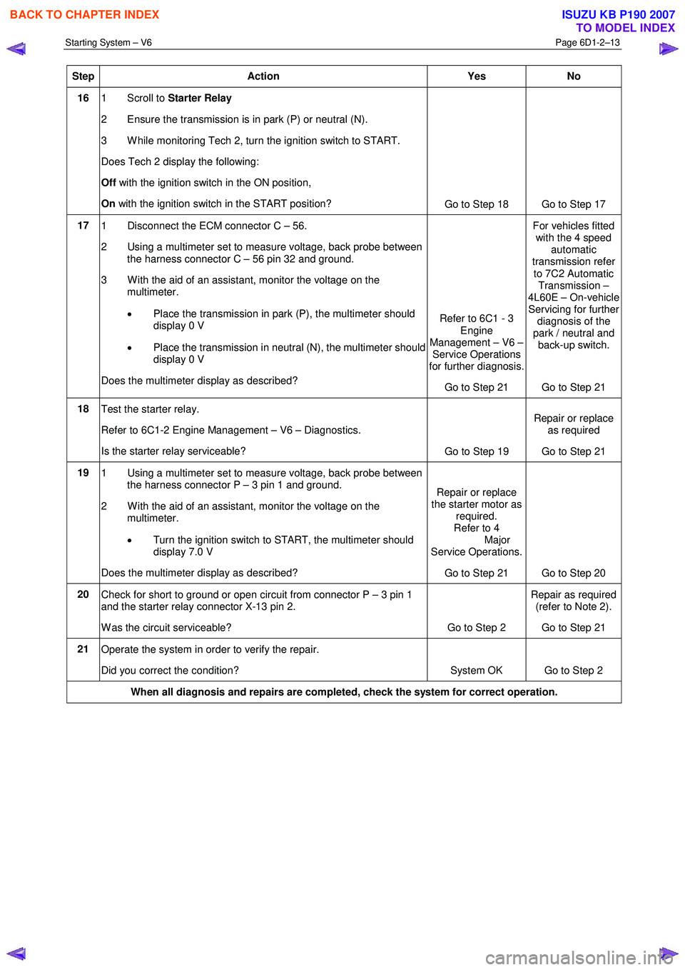
Starting System – V6 Page 6D1-2–13
Step Action Yes No
16 1 Scroll to Starter Relay
2 Ensure the transmission is in park (P) or neutral (N).
3 W hile monitoring Tech 2, turn the ignition switch to START.
Does Tech 2 display the following:
Off with the ignition switch in the ON position,
On with the ignition switch in the START position?
Go to Step 18 Go to Step 17
17 1 Disconnect the ECM connector C – 56.
2 Using a multimeter set to measure voltage, back probe between the harness connector C – 56 pin 32 and ground.
3 W ith the aid of an assistant, monitor the voltage on the multimeter.
• Place the transmission in park (P), the multimeter should
display 0 V
• Place the transmission in neutral (N), the multimeter should
display 0 V
Does the multimeter display as described? Refer to 6C1 - 3
Engine
Management – V6 – Service Operations
for further diagnosis.
Go to Step 21 For vehicles fitted
with the 4 speed automatic
transmission refer
to 7C2 Automatic Transmission –
4L60E – On-vehicle Servicing for further
diagnosis of the
park / neutral and back-up switch.
Go to Step 21
18 Test the starter relay.
Refer to 6C1-2 Engine Management – V6 – Diagnostics.
Is the starter relay serviceable? Go to Step 19 Repair or replace
as required
Go to Step 21
19 1 Using a multimeter set to measure voltage, back probe between
the harness connector P – 3 pin 1 and ground.
2 W ith the aid of an assistant, monitor the voltage on the multimeter.
• Turn the ignition switch to START, the multimeter should
display 7.0 V
Does the multimeter display as described? Repair or replace
the starter motor as required.
Refer to 4
Major
Service Operations.
Go to Step 21 Go to Step 20
20 Check for short to ground or open circuit from connector P – 3 pin 1
and the starter relay connector X-13 pin 2.
W as the circuit serviceable? Go to Step 2 Repair as required
(refer to Note 2).
Go to Step 21
21 Operate the system in order to verify the repair.
Did you correct the condition? System OK Go to Step 2
When all diagnosis and repairs are completed, check the system for correct operation.
BACK TO CHAPTER INDEX
TO MODEL INDEX
ISUZU KB P190 2007
Page 3624 of 6020

Starting System – V6 Page 6D1-2–16
Engine Compartment Relay And Fuse Panel
Figure 6D1-2 – 4
1 Remove fuses SBF5 and SBF9 from the engine compartment fuse panel to disable the ignition and prevent the engine from starting, refer to 8A Electrical Body and Chassis.
2 Chock the wheels.
3 For vehicles fitted with automatic transmission ensure the transmission is in P (park) or N (neutral) and the hand brake is applied.
4 Ensure the engine is at room temperature or normal operating temperature and in good working order.
Bad Connection Test
A bad connection appears as a voltage reading when the multimeter leads are connected to two different positive (or
negative) connections.
1 Using a multimeter set to measure voltage, connect the multimeter’s positive lead to the positive battery post.
2 Connect the multimeter’s negative lead to the starter motor M terminal.
3 Record the voltage that displayed during cranking.
4 Repeat this with the multimeter’s negative lead connected to the solenoid switch connector P – 4 pin B (circuit 1).
5 Also repeat this connecting the multimeter’s negative lead to the battery cable strands.
6 Restore all connections that show a significant resistance (voltage reading).
BACK TO CHAPTER INDEX
TO MODEL INDEX
ISUZU KB P190 2007
Page 3625 of 6020

Starting System – V6 Page 6D1-2–17
Starter Motor Ground Test
1 Using a multimeter set to measure voltage, connect
the multimeter’s positive lead (1) to the negative
battery post.
Connect the lead to the actual battery post
and not to the cable or connector.
2 Connect the multimeter’s negative lead (2) to the starter motor housing.
3 Record the voltage that displayed during cranking.
4 Repeat this connecting the multimeter’s negative lead to the battery cable strands.
5 Restore all ground connections that show a significant resistance.
Figure 6D1-2 – 5
Switching Circuit Test
1 Using a multimeter set to measure voltage, connect
the multimeter’s negative lead (1) to the solenoid
switch connector P – 3 pin 1.
2 Connect the multimeter‘s positive lead (2) to the positive battery post.
3 Crank the engine.
4 Record the voltage that displayed during cranking.
Maximum switching
circuit voltage difference.........................................2.5 V
5 If the voltage is above the specification, test the solenoid switching circuit to locate the cause of the
high resistance and restore the connection.
Figure 6D1-2 – 6
BACK TO CHAPTER INDEX
TO MODEL INDEX
ISUZU KB P190 2007
Page 3626 of 6020

Starting System – V6 Page 6D1-2–18
Cranking Voltage Test
1 Using a multimeter set to measure voltage, attach
the multimeter’s negative lead to ground and the
multimeter’s positive lead to starter solenoid
connector P – 3 pin 1 (3) of the solenoid switch.
Do not crank the engine for more than
30 seconds at a time. Allow 2 minutes for
the starter motor to cool down between
tests.
3 Crank the engine.
4 Record the voltage that displayed during cranking.
Minimum cranking
voltage.................................................................9.0 V
5 Remove and repair or replace the starter motor and solenoid switch if the voltage is below the
specifications and cranks poorly. Refer to 4
Major Service Operations. Figure 6D1-2 – 7
Current Draw Test
1 Using a multimeter set to measure voltage, attach the multimeter’s positive lead to the positive battery post.
2 Attach the same multimeter’s negative lead to the negative battery post.
3 Using a multimeter set to measure current, attach the multimeter’s positive lead to the battery post.
4 Connect the negative lead of the multimeter set to measure current to a battery loading device, for example a carbon pile.
5 Connect the free lead of the battery loading device to the negative battery terminal.
6 Set the battery loading device to maximum resistance (open).
7 Crank the engine.
8 Record the voltage that displayed during cranking.
9 W ith the ignition in the OFF position, adjust the battery loading device so the reading of the multimeter set to measure voltage matches the reading recorded in the last step.
10 Record the current draw from the battery loading device.
11 Set the battery loading device back to ‘open’.
12 Check the current draw is within specifications.
Cranking current range ................................ 100 – 140 A
13 Remove and repair or replace the starter motor and solenoid switch if the current draw is outside the specification. Refer to 4 Major Service Operations.
BACK TO CHAPTER INDEX
TO MODEL INDEX
ISUZU KB P190 2007