ISUZU KB P190 2007 Workshop Repair Manual
Manufacturer: ISUZU, Model Year: 2007, Model line: KB P190, Model: ISUZU KB P190 2007Pages: 6020, PDF Size: 70.23 MB
Page 2761 of 6020
Engine Mechanical – V6 Page 6A1–282
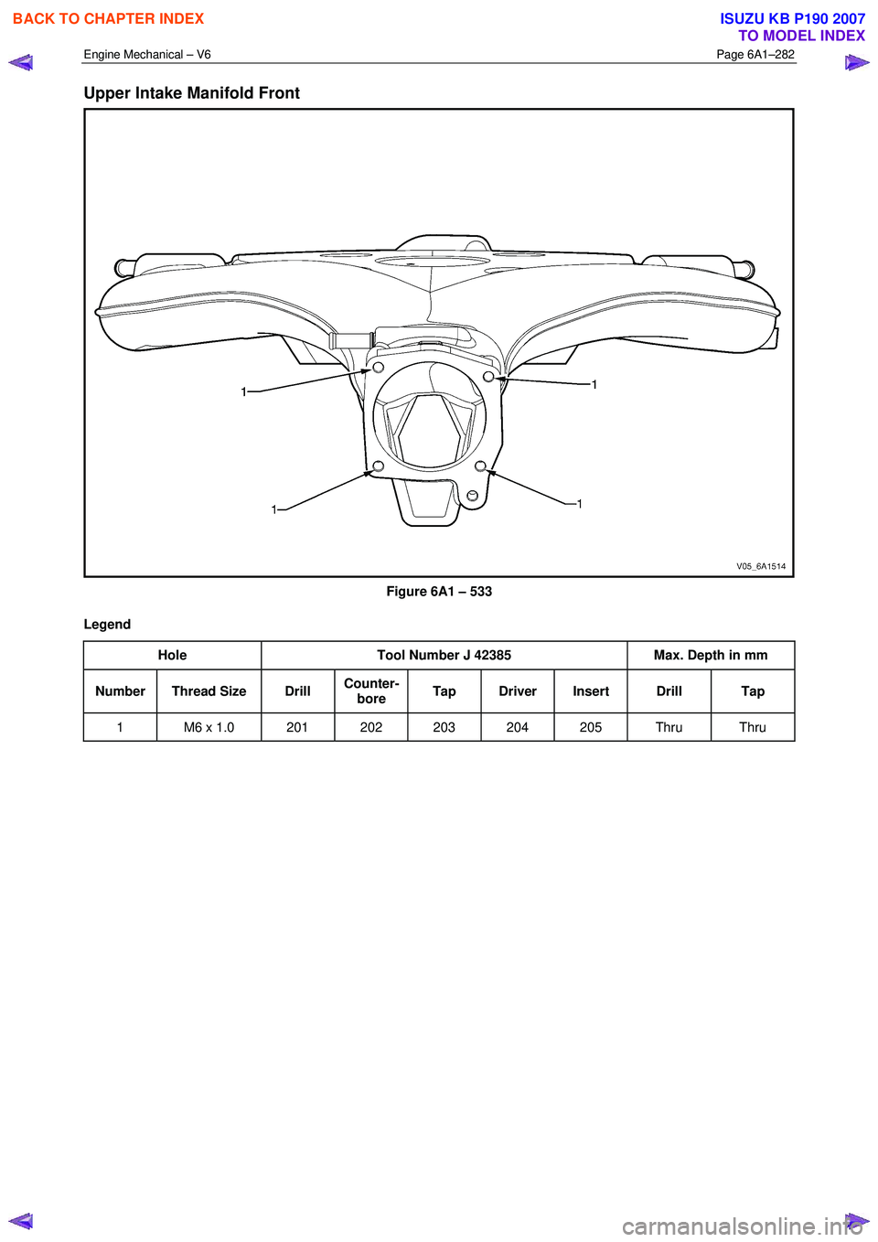
Upper Intake Manifold Front
Figure 6A1 – 533
Legend Hole Tool Number J 42385 Max. Depth in mm
Number Thread Size Drill Counter-
bore Tap Driver Insert Drill Tap
1 M6 x 1.0 201 202 203 204 205 Thru Thru
BACK TO CHAPTER INDEX
TO MODEL INDEX
ISUZU KB P190 2007
Page 2762 of 6020
Engine Mechanical – V6 Page 6A1–283
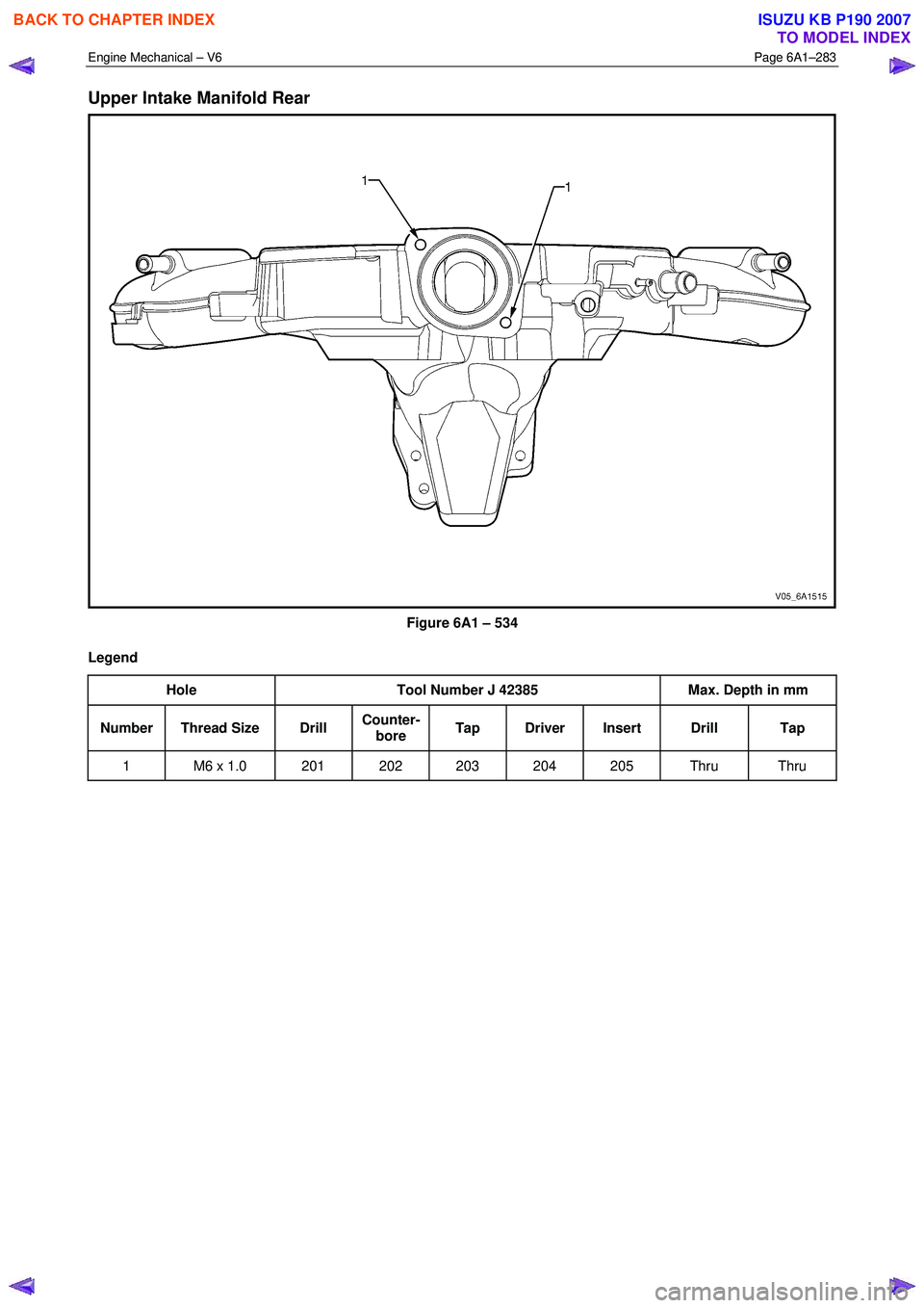
Upper Intake Manifold Rear
Figure 6A1 – 534
Legend Hole Tool Number J 42385 Max. Depth in mm
Number Thread Size Drill Counter-
bore Tap Driver Insert Drill Tap
1 M6 x 1.0 201 202 203 204 205 Thru Thru
BACK TO CHAPTER INDEX
TO MODEL INDEX
ISUZU KB P190 2007
Page 2763 of 6020
Engine Mechanical – V6 Page 6A1–284
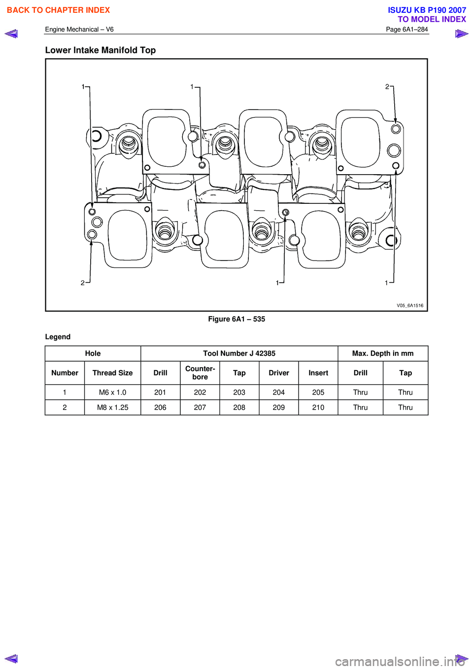
Lower Intake Manifold Top
Figure 6A1 – 535
Legend Hole Tool Number J 42385 Max. Depth in mm
Number Thread Size Drill Counter-
bore Tap Driver Insert Drill Tap
1 M6 x 1.0 201 202 203 204 205 Thru Thru
2 M8 x 1.25 206 207 208 209 210 Thru Thru
BACK TO CHAPTER INDEX
TO MODEL INDEX
ISUZU KB P190 2007
Page 2764 of 6020
Engine Mechanical – V6 Page 6A1–285
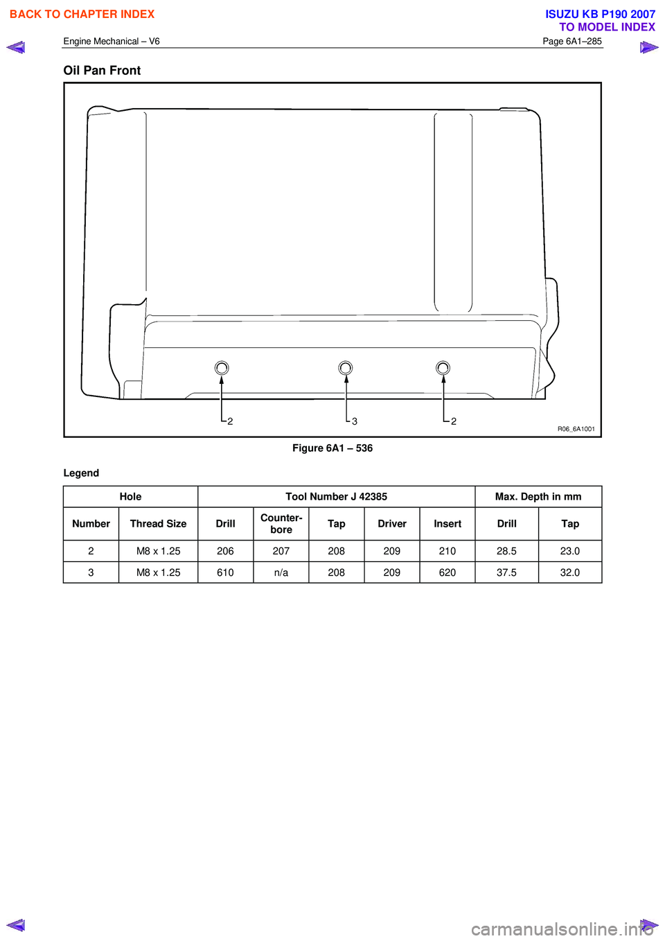
Oil Pan Front
Figure 6A1 – 536
Legend Hole Tool Number J 42385 Max. Depth in mm
Number Thread Size Drill Counter-
bore Tap Driver Insert Drill Tap
2 M8 x 1.25 206 207 208 209 210 28.5 23.0
3 M8 x 1.25 610 n/a 208 209 620 37.5 32.0
BACK TO CHAPTER INDEX
TO MODEL INDEX
ISUZU KB P190 2007
Page 2765 of 6020
Engine Mechanical – V6 Page 6A1–286
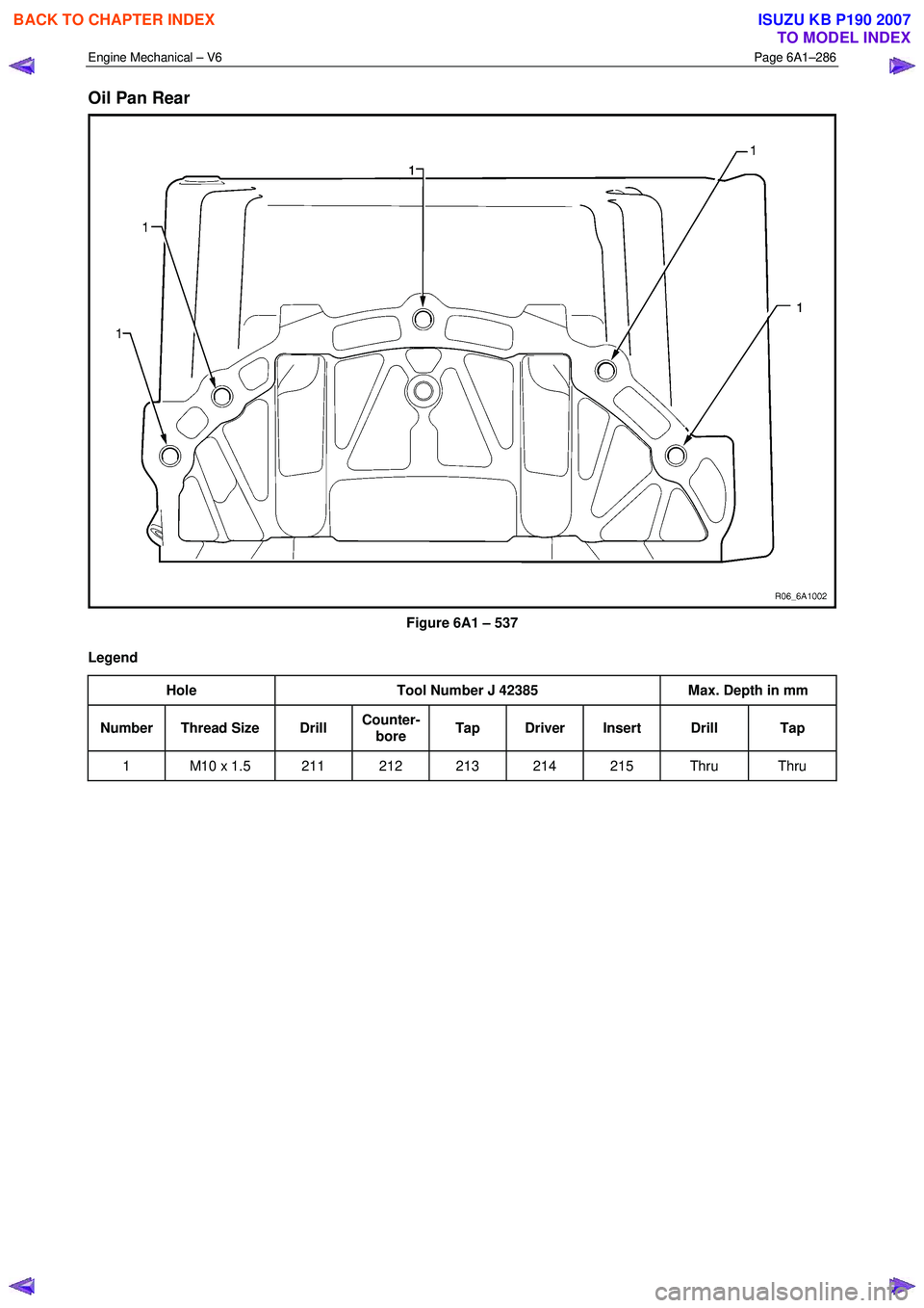
Oil Pan Rear
Figure 6A1 – 537
Legend Hole Tool Number J 42385 Max. Depth in mm
Number Thread Size Drill Counter-
bore Tap Driver Insert Drill Tap
1 M10 x 1.5 211 212 213 214 215 Thru Thru
BACK TO CHAPTER INDEX
TO MODEL INDEX
ISUZU KB P190 2007
Page 2766 of 6020
Engine Mechanical – V6 Page 6A1–287
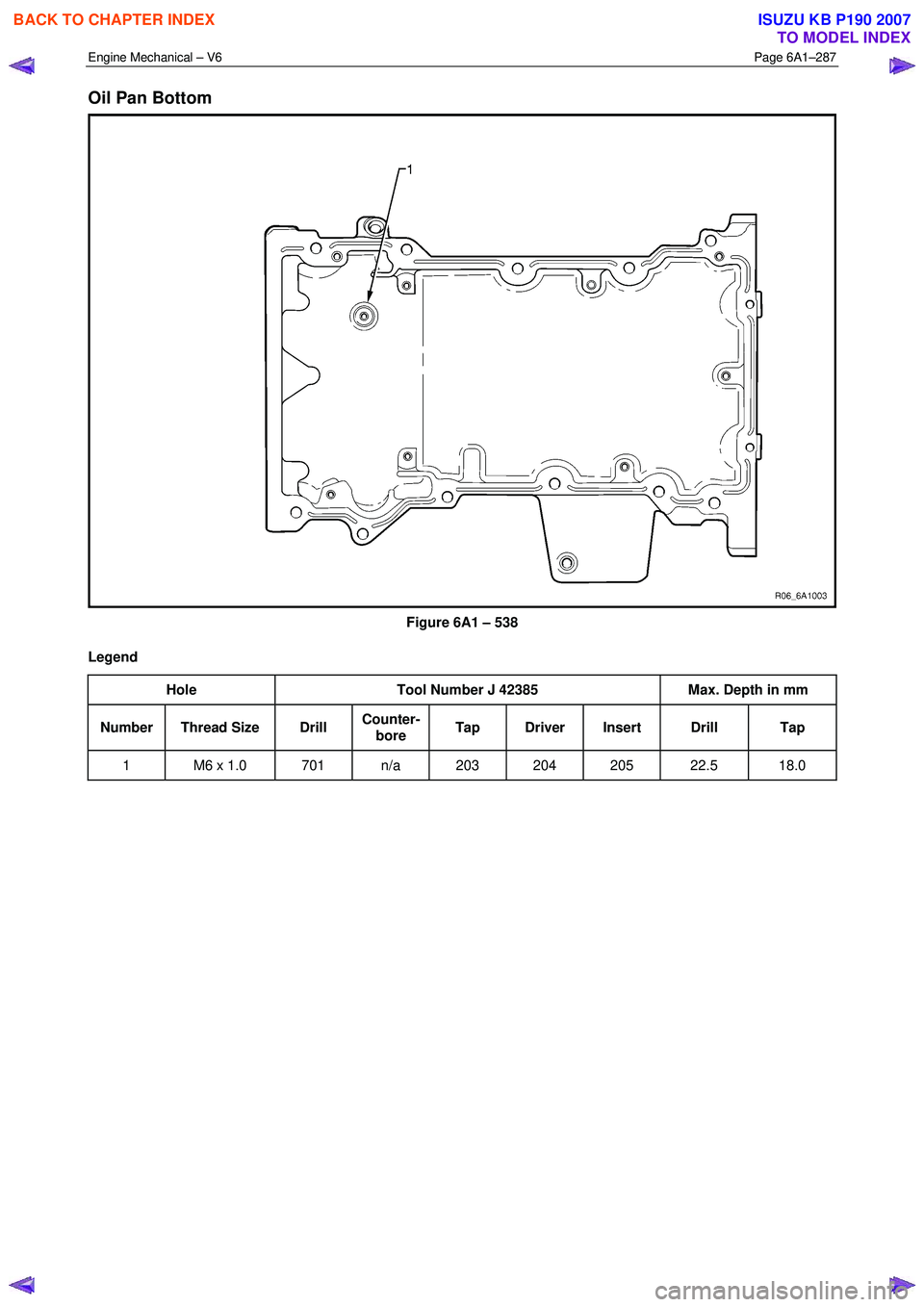
Oil Pan Bottom
Figure 6A1 – 538
Legend Hole Tool Number J 42385 Max. Depth in mm
Number Thread Size Drill Counter-
bore Tap Driver Insert Drill Tap
1 M6 x 1.0 701 n/a 203 204 205 22.5 18.0
BACK TO CHAPTER INDEX
TO MODEL INDEX
ISUZU KB P190 2007
Page 2767 of 6020

Engine Mechanical – V6 Page 6A1–288
5 Specifications
General
Engine Type.................................................................................................................... ..... V6
Bank Angle ..................................................................................................................... .... 60°
Displacement ............................................................................................ 3.6 litre (3,565 cm3)
Bore ........................................................................................................................... .... 94 mm
Stroke ......................................................................................................................... 85.6 mm
Compression Ratio ......................................................................................................... 10.2: 1
Cranking Speed at 40 °C .............................................................................................80 r.p.m.
Spark Plug Gap ............................................................................................................ 1.1 m m
Firing Order............................................................................................................. 1-2-3- 4-5-6
Cylinder Block
Cylinder Bore Diameter ........................................................................... 93.992 – 94.008 mm
Cylinder Out-of-Round – Production Maximum ........................................................ 0.013 mm
Crankshaft Main bearing bore Diameter .................................................. 72.867 – 72.881 mm
Cylinder Head Deck Surface Flatness ........................................................................ 0.05 mm
Crankshaft
Connecting Rod Journal Diameter ........................................................... 55.992 – 56.008 mm
Connecting Rod Journal Out-of-Round..................................................................... 0.005 mm
Connecting Rod Journal Taper ................................................................................ .0.005 mm
Connecting Rod Journal Width (Production)........................................................... 22.000 mm
Connecting Rod Journal Width (Service limit).......................................... 21.920 – 22.080 mm
Crankshaft End Play .................................................................................... 0.100 – 0.330 mm
Crankshaft Main Bearing Clearance ............................................................ 0.010 – 0.060 mm
Crankshaft Main Journal Diameter ......................................................... .67.992 – 68.008 mm
Crankshaft Main Journal Out-of-Round .................................................................... 0.005 mm
Crankshaft Main Journal Taper................................................................................ .0.005 mm
Crankshaft Main Journal Width, #2, 4 (Production) ....................................................... 24 mm
Crankshaft Main Journal Width, #2, 4 (Service)....................................... 23.900 – 24.100 mm
Crankshaft Main Journal Width, #3 (Production) .................................................... 24.400 mm
Crankshaft Main Journal Width, #3 (Service) .......................................... 24.360 – 24.440 mm
Crankshaft Main Journal Thrust Wall Runout .............................................. 0.000 – 0.040 mm
Crankshaft Main Journal Thrust Wall Square .............................................. 0.000 – 0.010 mm
Crankshaft Rear Flange Runout ............................................................................... 0.025 mm
Crankshaft Reluctor Ring Runout - Maximum........................................................... 1.500 mm
Crankshaft Thrust Bearing Clearance.......................................................... 0.076 – 0.305 mm
Crankshaft Thrust Surface Runout ........................................................................... 0.040 mm
Crankshaft Thrust Surface – Height Diameter ........................................................ 95.000 mm
Connecting Rod
Connecting Rod Length - Bore Centre-to-Centre.................................................. 150.400 mm
Connecting Rod Bore Diameter - Bearing End ........................................ 59.620 – 59.636 mm
Connecting Rod Bore Diameter - Pin End ............................................... 24.007 – 24.021 mm
Connecting Rod Width ........................................................................................... 21.775 mm
Connecting Rod Side Clearance.................................................................. 0.095 – 0.355 mm
Connecting Rod Bearing Clearance ............................................................ 0.010 – 0.070 mm
Piston
Piston Diameter ....................................................................................... 93.956 – 93.974 mm
Piston Pin Bore Diameter ........................................................................ 24.005 – 24.009 mm
Piston Ring Groove Width - First (Top) Compression Ring ......................... 1.220 – 1.240 mm
Piston Ring Groove Width - Second Compression Ring .............................. 1.510 – 1.530 mm
BACK TO CHAPTER INDEX
TO MODEL INDEX
ISUZU KB P190 2007
Page 2768 of 6020

Engine Mechanical – V6 Page 6A1–289
Piston Ring Groove Width - Oil Control Ring ............................................... 2.510 – 2.530 mm
Piston to Bore Clearance ............................................................................. 0.026 – 0.052 mm
Piston Pin
Piston Pin Diameter ..................................................................................23.997 - 24.000 mm
Piston Pin Length..................................................................................... 60.600 – 61.100 mm
Piston Pin Clearance to Connecting Rod Bore ............................................. 0.007 – 0.024mm
Piston Pin Clearance to Piston Pin Bore....................................................... 0.004 – 0.012mm
Piston Rings
Piston Ring to Groove Clearance:
• First (Top) Compression Ring............................................................... 0.030 – 0.065 mm
• Second Compression Ring ................................................................... 0.015 – 0.060 mm
• Oil Control Ring .................................................................................... 0.030 – 0.170 mm
Piston Ring End Gap:
• First (Top) Compression Ring............................................................... 0.150 – 0.300 mm
• Second Compression Ring ................................................................... 0.280 – 0.480 mm
• Oil Control Ring .................................................................................... 0.150 – 0.600 mm
Cylinder Head
Combustion Chamber Volume.................................................................................. 53.600 cc
Valve Guide Bore Diameter – Intake ........................................................... 6.000 – 6.020 mm
Valve Guide Bore Diameter – Exhaust ........................................................ 6.000 – 6.020 mm
Valve Guide Installed Height.................................................................... 14.050 – 14.550 mm
Stationary Hydraulic Lash Adjuster (SHLA) Bore Diameter ..................... 12.008 – 12.030 mm
Valve Seat Angle – Seating Surface ................................................................................... 45 °
Valve Seat Angle – Relief Surface ...................................................................................... 30 °
Valve Seat Angle – Undercut Surface ................................................................................ 60 °
Valve Seat Runout – Maximum ................................................................................ 0.050 mm
Valve Seat Width – Exhaust Seating Surface .............................................. 1.400 – 1.800 mm
Valve Seat Width – Exhaust Relief Surface ................................................. 0.700 – 0.900 mm
Valve Seat Width – Intake Seating Surface ................................................. 1.000 – 1.400 mm
Valve Seat Width – Intake Relief Surface .................................................... 0.500 – 0.700 mm
Engine Block Deck Surface Flatness .......................................................................... 0.05 mm
Exhaust Manifold Deck Surface Flatness ................................................................... 0.25 mm
Intake Manifold Deck Surface Flatness ...................................................................... 0.05 mm
Valve System
Face Angle..................................................................................................................... 44.25°
Face Runout ............................................................................................................. 0.038 m m
Valve Face Width – Exhaust..................................................................................... 2.750 mm
Valve Face Width – Intake ........................................................................................ 2.180 mm
Valve Head Diameter – Exhaust .............................................................. 30.470 – 30.730 mm
Valve Head Diameter – Intake ................................................................. 36.830 – 37.090 mm
Valve Installed Height .................................................................................. 35.26 – 36.69 mm
Valve Length – Exhaust .......................................................................................... 97.110 mm
Valve Length – Intake ........................................................................................... 101.230 mm
Valve Stem Diameter (standard).................................................................. 5.955 – 5.975 mm
Valve Stem Diameter (oversize) .................................................................. 6.013 – 6.033 mm
Valve Stem to Guide Clearance................................................................... 0.025 – 0.065 mm
Hydraulic Lash Adjuster Diameter ........................................................... 11.986 – 12.000 mm
Hydraulic Lash Adjuster to Bore Clearance ................................................. 0.037 – 0.041 mm
Rocker Arm/Camshaft Follower Ratio............................................................................. 1.68:1
Rocker Arm/Camshaft Follower Roller Diameter ..................................... 17.740 – 17.800 mm
Valve Spring Free Length ........................................................................ 42.500 – 45.500 mm
BACK TO CHAPTER INDEX
TO MODEL INDEX
ISUZU KB P190 2007
Page 2769 of 6020
Engine Mechanical – V6 Page 6A1–290
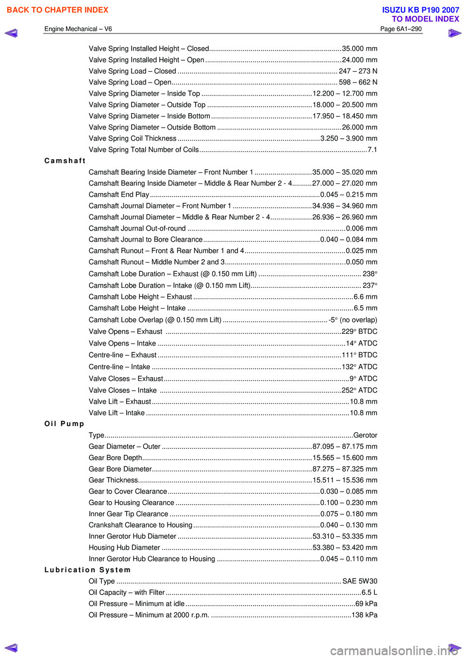
Valve Spring Installed Height – Closed................................................................... 35.000 mm
Valve Spring Installed Height – Open ..................................................................... 24.000 mm
Valve Spring Load – Closed ................................................................................. 247 – 273 N
Valve Spring Load – Open.................................................................................... 598 – 662 N
Valve Spring Diameter – Inside Top ........................................................ 12.200 – 12.700 mm
Valve Spring Diameter – Outside Top ..................................................... 18.000 – 20.500 mm
Valve Spring Diameter – Inside Bottom ................................................... 17.950 – 18.450 mm
Valve Spring Diameter – Outside Bottom ............................................................... 26.000 mm
Valve Spring Coil Thickness ........................................................................ 3.250 – 3.900 mm
Valve Spring Total Number of Coils ..................................................................................... 7.1
Camshaft
Camshaft Bearing Inside Diameter – Front Number 1 ............................. 35.000 – 35.020 mm
Camshaft Bearing Inside Diameter – Middle & Rear Number 2 - 4.......... 27.000 – 27.020 mm
Camshaft End Play ...................................................................................... 0.045 – 0.215 mm
Camshaft Journal Diameter – Front Number 1 ........................................ 34.936 – 34.960 mm
Camshaft Journal Diameter – Middle & Rear Number 2 - 4..................... 26.936 – 26.960 mm
Camshaft Journal Out-of-round ................................................................................ 0.006 mm
Camshaft Journal to Bore Clearance ........................................................... 0.040 – 0.084 mm
Camshaft Runout – Front & Rear Number 1 and 4 ................................................... 0.025 mm
Camshaft Runout – Middle Number 2 and 3............................................................ .0.050 mm
Camshaft Lobe Duration – Exhaust (@ 0.150 mm Lift) .................................................... 238 °
Camshaft Lobe Duration – Intake (@ 0.150 mm Lift)........................................................ 237 °
Camshaft Lobe Height – Exhaust ................................................................................. 6.6 mm
Camshaft Lobe Height – Intake .................................................................................... 6.5 mm
Camshaft Lobe Overlap (@ 0.150 mm Lift) ..................................................... -5 ° (no overlap)
Valve Opens – Exhaust .........................................................................................229 ° BTDC
Valve Opens – Intake ...............................................................................................14 ° ATDC
Centre-line – Exhaust .............................................................................................111 ° BTDC
Centre-line – Intake ................................................................................................132 ° ATDC
Valve Closes – Exhaust ..............................................................................................9 ° ATDC
Valve Closes – Intake ............................................................................................252 ° ATDC
Valve Lift – Exhaust .................................................................................................... 10.8 mm
Valve Lift – Intake ....................................................................................................... 10.8 mm
Oil Pump
Type........................................................................................................................... ...Gerotor
Gear Diameter – Outer ............................................................................ 87.095 – 87.175 mm
Gear Bore Depth...................................................................................... 15.565 – 15.600 mm
Gear Bore Diameter................................................................................. 87.275 – 87.325 mm
Gear Thickness........................................................................................ 15.511 – 15.536 mm
Gear to Cover Clearance ............................................................................. 0.030 – 0.085 mm
Gear to Housing Clearance ......................................................................... 0.100 – 0.230 mm
Inner Gear Tip Clearance ............................................................................ 0.075 – 0.180 mm
Crankshaft Clearance to Housing ................................................................ 0.040 – 0.130 mm
Inner Gerotor Hub Diameter .................................................................... 53.310 – 53.335 mm
Housing Hub Diameter ............................................................................ 53.380 – 53.420 mm
Inner Gerotor Hub Clearance to Housing .................................................... 0.045 – 0.110 mm
Lubrication System
Oil Type .................................................................................................................. SAE 5 W 30
Oil Capacity – with Filter ................................................................................................... 6. 5 L
Oil Pressure – Minimum at idle ......................................................................................69 kPa
Oil Pressure – Minimum at 2000 r.p.m. .......................................................................138 kPa
BACK TO CHAPTER INDEX
TO MODEL INDEX
ISUZU KB P190 2007
Page 2770 of 6020
Engine Mechanical – V6 Page 6A1–291
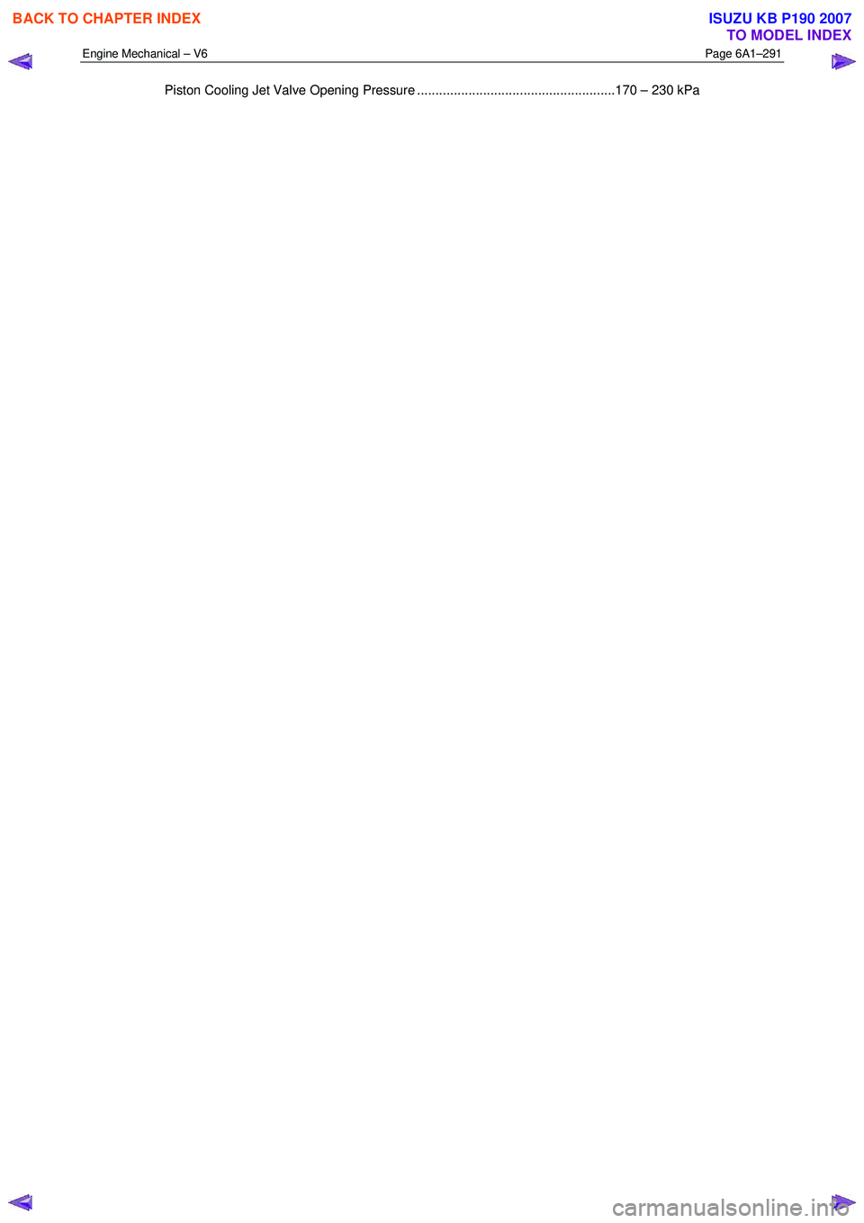
Piston Cooling Jet Valve Opening Pressure ......................................................170 – 230 kPa
BACK TO CHAPTER INDEX
TO MODEL INDEX
ISUZU KB P190 2007