catalytic converter ISUZU KB P190 2007 Workshop Owner's Manual
[x] Cancel search | Manufacturer: ISUZU, Model Year: 2007, Model line: KB P190, Model: ISUZU KB P190 2007Pages: 6020, PDF Size: 70.23 MB
Page 2454 of 6020
ENGINE EXHAUST 6F-5
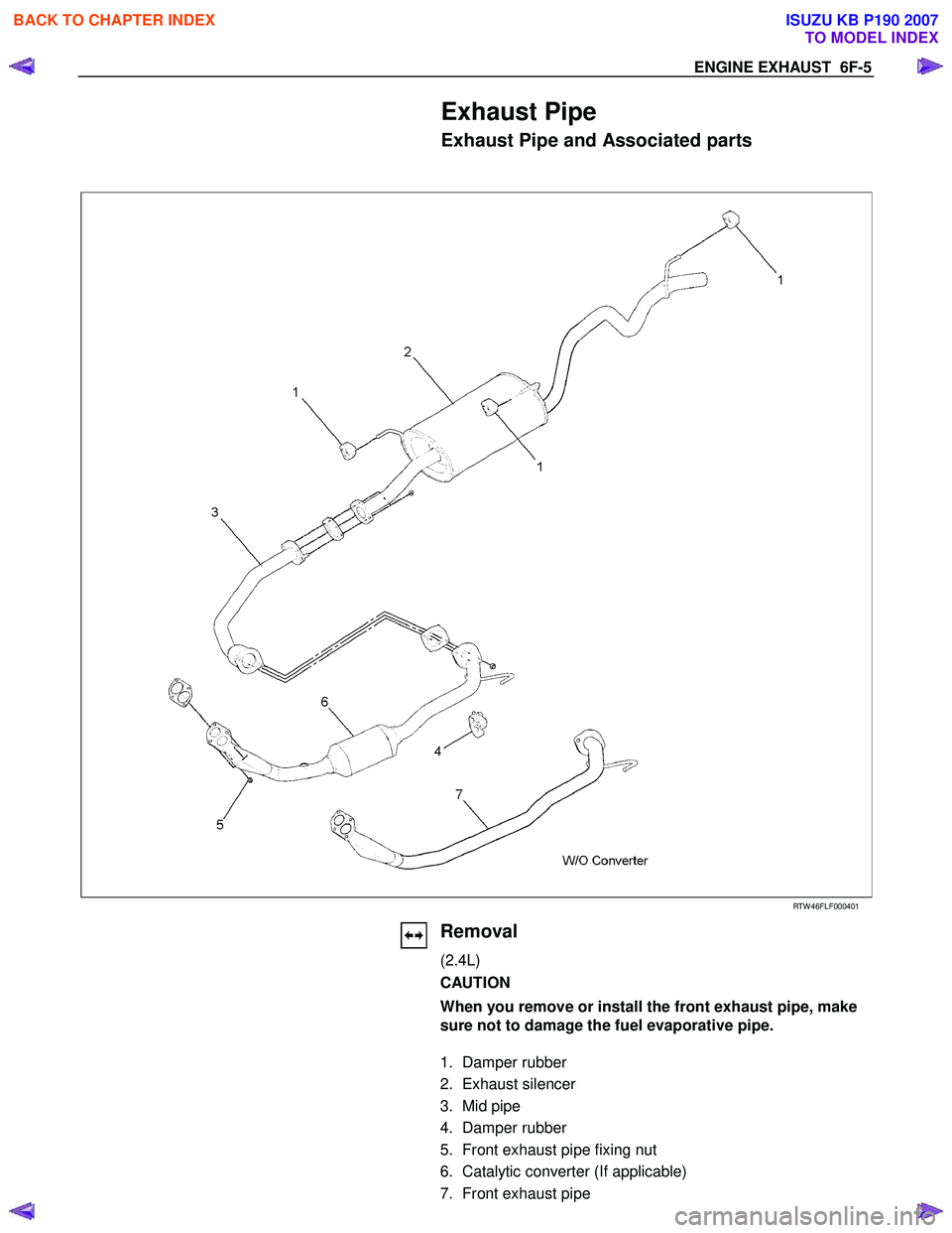
Exhaust Pipe
Exhaust Pipe and Associated parts
RTW 46FLF000401
Removal
(2.4L)
CAUTION
When you remove or install the front exhaust pipe, make
sure not to damage the fuel evaporative pipe.
1. Damper rubber
2. Exhaust silencer
3. Mid pipe
4. Damper rubber
5. Front exhaust pipe fixing nut
6. Catalytic converter (If applicable)
7. Front exhaust pipe
BACK TO CHAPTER INDEX
TO MODEL INDEX
ISUZU KB P190 2007
Page 2455 of 6020

6F-6 ENGINE EXHAUST
Installation
To install, follow the removal steps in the reverse order.
Important - Installation
1. Front Exhaust Pipe Flange Nut
Connect the exhaust pipe to the exhaust manifold.
Front exhaust pipe to manifold nut.
Torque
N⋅m (kgf ⋅m)
28 (2.9)
Inspection
Make the necessary adjustments, and part replacements if
excessive wear or damage is discover during inspection.
1. Front Exhaust Pipe
2. Center Exhaust Pipe and Catalytic Converter Flange Nut
3. Exhaust Pipe Damper Rubber
4. Exhaust Silencer with Rear Exhaust Pipe
Check the pipes for for corrosion, cracking , damage or
misalignment and repair if required.
Check the damper rubber for deterioration or damage and
repair if required.
BACK TO CHAPTER INDEX
TO MODEL INDEX
ISUZU KB P190 2007
Page 2456 of 6020
ENGINE EXHAUST 6F-7
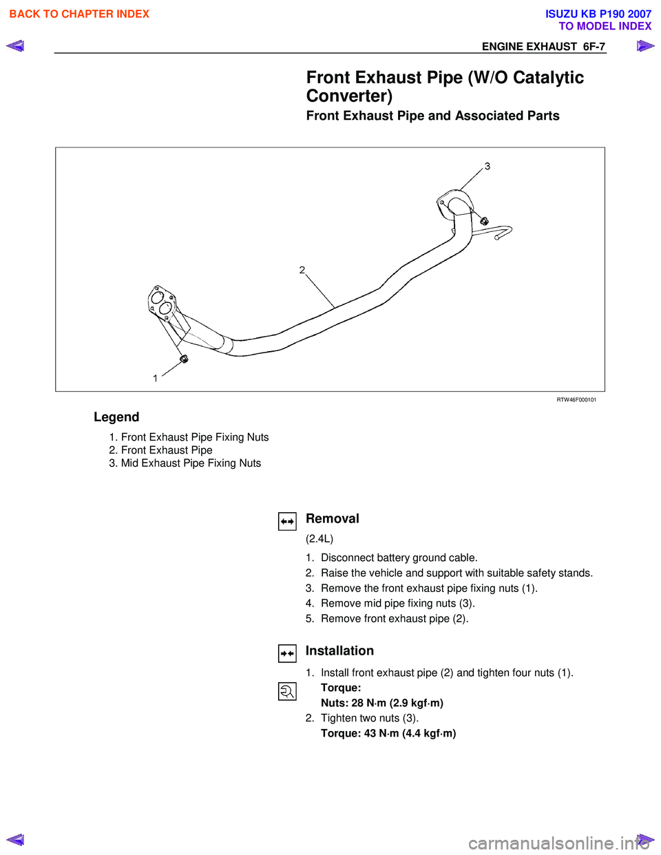
Front Exhaust Pipe (W/O Catalytic
Converter)
Front Exhaust Pipe and Associated Parts
RTW 46F000101
Legend
1. Front Exhaust Pipe Fixing Nuts
2. Front Exhaust Pipe
3. Mid Exhaust Pipe Fixing Nuts
Removal
(2.4L)
1. Disconnect battery ground cable.
2. Raise the vehicle and support with suitable safety stands.
3. Remove the front exhaust pipe fixing nuts (1).
4. Remove mid pipe fixing nuts (3).
5. Remove front exhaust pipe (2).
Installation
1. Install front exhaust pipe (2) and tighten four nuts (1). Torque:
Nuts: 28 N ⋅
⋅⋅
⋅
m (2.9 kgf ⋅
⋅⋅
⋅
m)
2. Tighten two nuts (3). Torque: 43 N ⋅
⋅⋅
⋅
m (4.4 kgf ⋅
⋅⋅
⋅
m)
BACK TO CHAPTER INDEX
TO MODEL INDEX
ISUZU KB P190 2007
Page 2458 of 6020

ENGINE EXHAUST 6F-9
Catalytic Converter (If applicable)
Catalytic Converter and Associated Parts
RTW 46FSF000301
Legend
1. Catalytic Converter
2. O
2 Sensor Converter
3. Front Pipe Fixing Nuts
4. Mid Pipe Fixing Nuts
Removal
(2.4L)
1. Disconnect battery ground cable.
2. Raise the vehicle and support with suitable safety stands.
3. Remove front pipe fixing nuts (3).
4. Remove mid pipe fixing nuts (4).
5. Remove the O
2 sensor connector (2).
6. Remove the front exhaust pipe with catalytic converter (1).
Installation
1. Install Catalytic Converter (1) and tighten four to the specified torque:
Torque:
Fixing nuts: 28 N ⋅
⋅⋅
⋅
m (2.9 kgf ⋅
⋅⋅
⋅
m)
2. Tight two nuts (4) Torque:
Nuts: 43 N ⋅
⋅⋅
⋅
m (4.4 kgf ⋅
⋅⋅
⋅
m)
3. Connect the O
2 sensor connector (2).
BACK TO CHAPTER INDEX
TO MODEL INDEX
ISUZU KB P190 2007
Page 2459 of 6020

6F-10 ENGINE EXHAUST
3 WAY CATALYTIC CONVERTER
SYSTEM (If applicable)
N2
Inspection
Make the necessary adjustments, and part replacements if
excessive or damage is discovered during inspection.
Exhaust Pipe Assembly
1. Check connections for looseness or damage.
2. Check clamps for weakness, crack, or damage.
Catalytic Converter
Check for dents or damage.
If any part of the converter is damaged or dented, repair or
replace it.
Removal
1. Jack up the vehicle.
2. Check that the converter is cool.
3. Remove the bolts at the front and rear of the converter.
4. Remove the converter and gaskets.
BACK TO CHAPTER INDEX
TO MODEL INDEX
ISUZU KB P190 2007
Page 2463 of 6020

6F-14 ENGINE EXHAUST
Main Data and Specifications
Exhaust system
Pipe outside diameter ✕ thickness
Front pipe mm(in) 44.5 ✕ 1.5 (1.75 ✕0.059)
Middle pipe mm(in) 50.8 ✕ 1.5 (2.00 ✕ 0.059)
Rear pipe mm(in) 50.8 ✕ 1.5 (2.0 ✕ 0.059)
Silencer
Type Circular section-shell construction
of triple; double skin and end plates, internal construction of baffles and perforated tubes.
Number of suspension points
Type
Catalytic converter type (If applicable) 4
Rubber
Three way Catalytic Converter
BACK TO CHAPTER INDEX
TO MODEL INDEX
ISUZU KB P190 2007
Page 2508 of 6020

Engine Mechanical – V6 Page 6A1–29
2.3 Engine Misfire without Internal Engine
Noises
Cause Correction
Abnormalities, severe cracking, bumps or missing areas in
the accessory drive belt.
Abnormalities in the accessory drive system and/or
components may cause engine speed variations that result
in a misfire diagnostic trouble code (DTC). A misfire code
may be present without an actual misfire condition. Replace the accessory drive belt, refer to 3.5
Accessory
Drive Belt.
Refer to 6C1-2 Engine Management – V6 – Diagnostics to
check for DTCs.
W orn, damaged or misaligned accessory drive components
and excessive pulley run-out may lead to a misfire DTC.
A misfire code may be present without an actual misfire
condition. Inspect the components and repair or replace as required.
Refer to 6C1-2 Engine Management – V6 – Diagnostics to
check for DTCs.
Loose or incorrectly fitted flexplate or crankshaft balancer
assembly.
A misfire DTC may be present without an actual misfire
condition. Repair or replace the flexplate or crankshaft balancer as
required, refer to 3.13 Crankshaft Balancer Assembly
or 4.3 Flexplate Assembly.
Refer to 6C1-2 Engine Management – V6 – Diagnostics to
check for DTCs
Restricted exhaust system.
A severe restriction in the exhaust flow can cause
significant loss of engine performance and may set a DTC.
Possible causes of restrictions in the exhaust system
include collapsed/dented pipes and blocked mufflers and/or
catalytic converters. Repair or replace exhaust system components as required,
refer to 8B Exhaust System.
Refer to 6C1-2 Engine Management – V6 – Diagnostics to
check for DTCs
Incorrectly installed or damaged vacuum hoses. Repair or replace vacuum hoses as required.
Incorrect sealing between the intake manifold and cylinder
heads, upper intake manifold and lower intake manifold,
throttle body and intake manifold. Repair or replace the intake manifold, throttle body gaskets,
cylinder heads, throttle body as required.
Incorrectly installed or damaged barometric
pressure(BARO) sensor and/or seal. The seal should not
be torn or damaged. Repair or replace the BARO sensor and/or seal as
required, refer to 6C1-3 Engine Management – V6 –
Service Operations.
Incorrectly installed or damaged EVAP purge solenoid
and/or O-ring seal. Repair or replace the EVAP purge solenoid and/or seal as
required, refer to 6C1-3 Engine Management – V6 –
Service Operations
W orn or loose stationary hydraulic lash adjusters (SHLA)
and/or rocker arms.
The SHLAs, rocker arms and roller bearings should be
intact and in the correct position. Replace the SHLAs and/or rocker arms as required, refer to
3.21 Stationary Hydraulic Lash Adjuster or 3.20
Rocker Arm.
Stuck valves.
Carbon build up on the valve stems can result in the valves
not closing correctly. Repair or replace as required, refer to 3.22 Cylinder Head
Assembly.
Excessively worn or misaligned timing chain/s. Replace the timing chain/s and components as required,
refer to 3.16 Timing Chains, Tensioners, Shoes and
Guides.
W orn camshaft lobes. Replace the camshaft/s and SHLAs as required, refer to
3.19 Camshaft or 3.21 Stationary Hydraulic Lash
Adjuster.
Excessive oil pressure.
A lubrication system with excessive oil pressure may lead
to excessive lash adjuster pump-up and loss of
compression. 1 Perform an oil pressure test, refer to 3.1
Engine Oil.
2 Repair or replace the engine oil pump as required, refer to 3.17 Oil Pump Assembly.
BACK TO CHAPTER INDEX
TO MODEL INDEX
ISUZU KB P190 2007
Page 2668 of 6020
Engine Mechanical – V6 Page 6A1–189
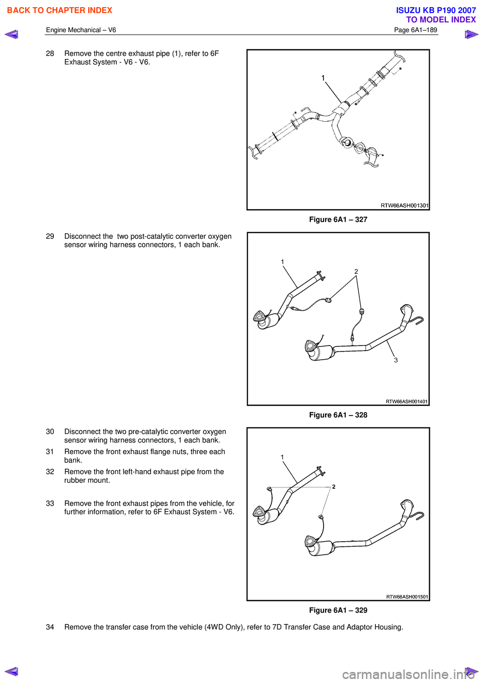
28 Remove the centre exhaust pipe (1), refer to 6F
Exhaust System - V6 - V6.
Figure 6A1 – 327
29 Disconnect the two post-catalytic converter oxygen sensor wiring harness connectors, 1 each bank.
Figure 6A1 – 328
30 Disconnect the two pre-catalytic converter oxygen sensor wiring harness connectors, 1 each bank.
31 Remove the front exhaust flange nuts, three each bank.
32 Remove the front left-hand exhaust pipe from the rubber mount.
33 Remove the front exhaust pipes from the vehicle, for further information, refer to 6F Exhaust System - V6.
Figure 6A1 – 329
34 Remove the transfer case from the vehicle (4W D Only), refer to 7D Transfer Case and Adaptor Housing.
BACK TO CHAPTER INDEX
TO MODEL INDEX
ISUZU KB P190 2007
Page 2809 of 6020

Engine Mechanical – V6 Page 6A1–32
Page 6A1–32
2.3 Engine Misfire without Internal Engine
Noises
Cause Correction
Abnormalities, severe cracking, bumps or missing areas in
the accessory drive belt.
Abnormalities in the accessory drive system and/or
components may cause engine speed variations that result
in a misfire diagnostic trouble code (DTC). A misfire code
may be present without an ac tual misfire condition. Replace the accessory drive belt, refer to 3.5 Accessory
Drive Belt.
Refer to 6C1-2 Engine Management – V6 – Diagnostics to
check for DTCs.
Worn, damaged or misaligned accessory drive components
and excessive pulley run-out may lead to a misfire DTC.
A misfire code may be present without an actual misfire
condition. Inspect the components and repair or replace as required.
Refer to 6C1-2 Engine Management – V6 – Diagnostics to
check for DTCs.
Loose or incorrectly fitted flexplate or crankshaft balancer
assembly.
A misfire DTC may be present without an actual misfire
condition. Repair or replace the flexplat
e or crankshaft balancer as
required, refer to 3.13 Crankshaft Balancer Assembly or
4.3 Flexplate Assembly.
Refer to 6C1-2 Engine Management – V6 – Diagnostics to
check for DTCs
Restricted exhaust system.
A severe restriction in the exhaust flow can cause
significant loss of engine performance and may set a DTC.
Possible causes of restrict ions in the exhaust system
include collapsed/dented pipes and blocked mufflers and/or
catalytic converters. Repair or replace exhaust syst
em components as required,
refer to 8B Exhaust System.
Refer to 6C1-2 Engine Management – V6 – Diagnostics to
check for DTCs
Incorrectly installed or damaged vacuum hoses. Repair or replace vacuum hoses as required.
Incorrect sealing between the intake manifold and cylinder
heads, upper intake manifold and lower intake manifold,
throttle body and intake manifold. Repair or replace the intake
manifold, throttle body gaskets,
cylinder heads, throttle body as required.
Incorrectly installed or damaged barometric
pressure(BARO) sensor and/or seal. The seal should not
be torn or damaged. Repair or replace the BARO sensor and/or seal as
required, refer to 6C1-3 Engine Management – V6 –
Service Operations.
Incorrectly installed or damaged EVAP purge solenoid
and/or O-ring seal. Repair or replace the EVAP purge solenoid and/or seal as
required, refer to 6C1-3 Engine Management – V6 –
Service Operations
Worn or loose stationary hydraulic lash adjusters (SHLA)
and/or rocker arms.
The SHLAs, rocker arms and roller bearings should be
intact and in the correct position. Replace the SHLAs and/or rocker arms as required, refer to
3.21 Stationary Hydraulic Las h Adjuster or 3.20 Rocker
Arm.
Stuck valves.
Carbon build up on the valve stem s can result in the valves
not closing correctly. Repair or replace as required, refer to 3.22 Cylinder Head
Assembly.
Excessively worn or misaligned timing chain/s. Replace the timing chain/s and components as required,
refer to 3.16 Timing Chains, Tensioners, Shoes and
Guides.
Worn camshaft lobes. Replace the camshaft/s and SHLAs as required, refer to
3.19 Camshaft or 3.21 Stati onary Hydraulic Lash Adjuster.
Excessive oil pressure.
A lubrication system with ex cessive oil pressure may lead
to excessive lash adjuster pump-up and loss of
compression. 1 Perform an oil pressure tes
t, refer to 3.1 Engine Oil.
2 Repair or replace the engine oil pump as required, refer to 3.17 Oil Pump Assembly.
BACK TO CHAPTER INDEX
TO MODEL INDEX
ISUZU KB P190 2007
Page 3021 of 6020

Engine Mechanical – V6 Page 6A1–244
Page 6A1–244
28 Remove the centre exhaust pipe (1), refer to
Section 6F Exhaust System - V6 .
Figure 6A1 – 417
29 Disconnect the two post-catalytic converter oxygen sensor wiring harness connectors, 1 each bank.
Figure 6A1 – 418
30 Disconnect the two pre-catalytic converter oxygen sensor wiring harness connectors, 1 each bank.
31 Remove the front exhaust flange nuts, three each bank.
32 Remove the front left-hand exhaust pipe from the rubber mount.
33 Remove the front exhaust pipes from the vehicle, for further information, refer to Section 6F Exhaust
System - V6 .
Figure 6A1 – 419
34 Remove the transfer case from t he vehicle (4WD Only), refer to Section 7D Transfer Case and Adaptor Housing .
BACK TO CHAPTER INDEX
TO MODEL INDEX
ISUZU KB P190 2007