display ISUZU KB P190 2007 Workshop Repair Manual
[x] Cancel search | Manufacturer: ISUZU, Model Year: 2007, Model line: KB P190, Model: ISUZU KB P190 2007Pages: 6020, PDF Size: 70.23 MB
Page 3806 of 6020
Automatic Transmission – 4L60E – Electrical Diagnosis Page 7C2–20
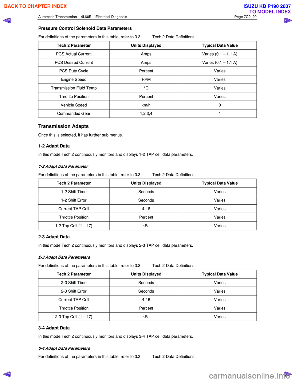
Pressure Control Solenoid Data Parameters
For definitions of the parameters in this table, refer to 3.3 Tech 2 Data Definitions.
Tech 2 Parameter Units Displayed Typical Data Value
PCS Actual Current Amps Varies (0.1 – 1.1 A)
PCS Desired Current Amps Varies (0.1 – 1.1 A)
PCS Duty Cycle Percent Varies
Engine Speed RPM Varies
Transmission Fluid Temp °C Varies
Throttle Position Percent Varies
Vehicle Speed km/h 0
Commanded Gear 1,2,3,4 1
Transmission Adapts
Once this is selected, it has further sub menus.
1-2 Adapt Data
In this mode Tech 2 continuously monitors and displays 1-2 TAP cell data parameters.
1-2 Adapt Data Parameter
For definitions of the parameters in this table, refer to 3.3 Tech 2 Data Definitions.
Tech 2 Parameter Units Displayed Typical Data Value
1-2 Shift Time Seconds Varies
1-2 Shift Error Seconds Varies
Current TAP Cell 4-16 Varies
Throttle Position Percent Varies
1-2 Tap Cell (1 – 17) kPa Varies
2-3 Adapt Data
In this mode Tech 2 continuously monitors and displays 2-3 TAP cell data parameters.
2-3 Adapt Data Parameters
For definitions of the parameters in this table, refer to 3.3 Tech 2 Data Definitions.
Tech 2 Parameter Units Displayed Typical Data Value
2-3 Shift Time Seconds Varies
2-3 Shift Error Seconds Varies
Current TAP Cell 4-16 Varies
Throttle Position Percent Varies
2-3 Tap Cell (1 – 17) kPa Varies
3-4 Adapt Data
In this mode Tech 2 continuously monitors and displays 3-4 TAP cell data parameters.
3-4 Adapt Data Parameters
For definitions of the parameters in this table, refer to 3.3 Tech 2 Data Definitions.
BACK TO CHAPTER INDEX
TO MODEL INDEX
ISUZU KB P190 2007
Page 3807 of 6020
Automatic Transmission – 4L60E – Electrical Diagnosis Page 7C2–21
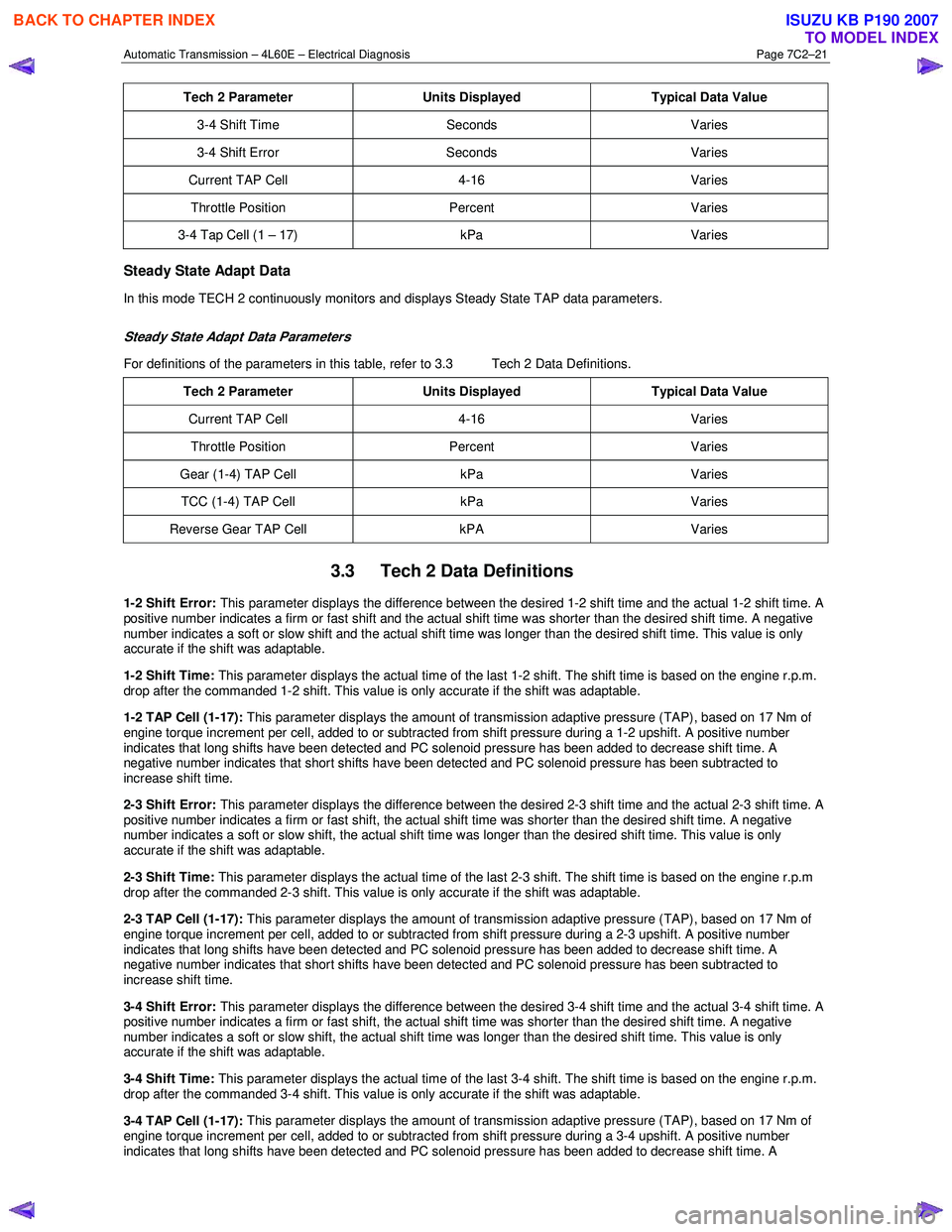
Tech 2 Parameter Units Displayed Typical Data Value
3-4 Shift Time Seconds Varies
3-4 Shift Error Seconds Varies
Current TAP Cell 4-16 Varies
Throttle Position Percent Varies
3-4 Tap Cell (1 – 17) kPa Varies
Steady State Adapt Data
In this mode TECH 2 continuously monitors and displays Steady State TAP data parameters.
Steady State Adapt Data Parameters
For definitions of the parameters in this table, refer to 3.3 Tech 2 Data Definitions.
Tech 2 Parameter Units Displayed Typical Data Value
Current TAP Cell 4-16 Varies
Throttle Position Percent Varies
Gear (1-4) TAP Cell kPa Varies
TCC (1-4) TAP Cell kPa Varies
Reverse Gear TAP Cell kPA Varies
3.3 Tech 2 Data Definitions
1-2 Shift Error: This parameter displays the difference between the desired 1-2 shift time and the actual 1-2 shift time. A
positive number indicates a firm or fast shift and the actual shift time was shorter than the desired shift time. A negative
number indicates a soft or slow shift and the actual shift time was longer than the desired shift time. This value is only
accurate if the shift was adaptable.
1-2 Shift Time: This parameter displays the actual time of the last 1-2 shift. The shift time is based on the engine r.p.m.
drop after the commanded 1-2 shift. This value is only accurate if the shift was adaptable.
1-2 TAP Cell (1-17): This parameter displays the amount of transmission adaptive pressure (TAP), based on 17 Nm of
engine torque increment per cell, added to or subtracted from shift pressure during a 1-2 upshift. A positive number
indicates that long shifts have been detected and PC solenoid pressure has been added to decrease shift time. A
negative number indicates that short shifts have been detected and PC solenoid pressure has been subtracted to
increase shift time.
2-3 Shift Error: This parameter displays the difference between the desired 2-3 shift time and the actual 2-3 shift time. A
positive number indicates a firm or fast shift, the actual shift time was shorter than the desired shift time. A negative
number indicates a soft or slow shift, the actual shift time was longer than the desired shift time. This value is only
accurate if the shift was adaptable.
2-3 Shift Time: This parameter displays the actual time of the last 2-3 shift. The shift time is based on the engine r.p.m
drop after the commanded 2-3 shift. This value is only accurate if the shift was adaptable.
2-3 TAP Cell (1-17): This parameter displays the amount of transmission adaptive pressure (TAP), based on 17 Nm of
engine torque increment per cell, added to or subtracted from shift pressure during a 2-3 upshift. A positive number
indicates that long shifts have been detected and PC solenoid pressure has been added to decrease shift time. A
negative number indicates that short shifts have been detected and PC solenoid pressure has been subtracted to
increase shift time.
3-4 Shift Error: This parameter displays the difference between the desired 3-4 shift time and the actual 3-4 shift time. A
positive number indicates a firm or fast shift, the actual shift time was shorter than the desired shift time. A negative
number indicates a soft or slow shift, the actual shift time was longer than the desired shift time. This value is only
accurate if the shift was adaptable.
3-4 Shift Time: This parameter displays the actual time of the last 3-4 shift. The shift time is based on the engine r.p.m.
drop after the commanded 3-4 shift. This value is only accurate if the shift was adaptable.
3-4 TAP Cell (1-17): This parameter displays the amount of transmission adaptive pressure (TAP), based on 17 Nm of
engine torque increment per cell, added to or subtracted from shift pressure during a 3-4 upshift. A positive number
indicates that long shifts have been detected and PC solenoid pressure has been added to decrease shift time. A
BACK TO CHAPTER INDEX
TO MODEL INDEX
ISUZU KB P190 2007
Page 3808 of 6020
Automatic Transmission – 4L60E – Electrical Diagnosis Page 7C2–22
negative number indicates that short shifts have been detected and PC solenoid pressure has been subtracted to
increase shift time.
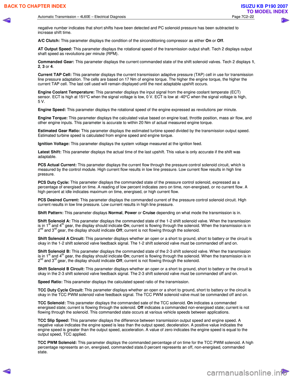
A/C Clutch: This parameter displays the condition of the sirconditioning compressor as either On or Off .
AT Output Speed: This parameter displays the rotational speed of the transmission output shaft. Tech 2 displays output
shaft speed as revolutions per minute (RPM).
Commanded Gear: This parameter displays the current commanded state of the shift solenoid valves. Tech 2 displays 1,
2 , 3 or 4.
Current TAP Cell: This parameter displays the current transmission adaptive pressure (TAP) cell in use for transmission
line pressure adaptation. The cells are based on 17 Nm of engine torque. The higher the engine torque, the higher the
current TAP cell. The last cell used will remain displayed until the next adaptable upshift occurs.
Engine Coolant Temperature: This parameter displays the input signal from the engine coolant temperate (ECT)
sensor. ECT is high at 151°C when the signal voltage is low, 0 V. ECT is low at -40°C when the signal voltage is high,
5 V.
Engine Speed: This parameter displays the rotational speed of the engine expressed as revolutions per minute.
Engine Torque: This parameter displays the calculated value based on engine load, throttle position, mass air flow, and
other engine inputs. This parameter is accurate to within 20 Nm of actual measured engine torque.
Estimated Gear Ratio: This parameter displays the estimated turbine speed divided by the transmission output speed.
Estimated turbine speed is calculated from engine speed and engine torque.
Ignition Voltage: This parameter displays the
system voltage measured at the ignition feed.
Latest Shift: This parameter displays the actual time of the last upshift. This value is only accurate if the shift was
adaptable.
PCS Actual Current: This parameter displays the current flow through the pressure control solenoid circuit, which is
measured by the control module. High current flow results in low line pressure. Low current flow results in high line
pressure.
PCS Duty Cycle: This parameter displays the commanded state of the pressure control solenoid, expressed as a
percentage of energised on time. A reading of low percent indicates zero on time, non-energised, or no current flow. A
high percent at idle indicates maximum on time, energised, or high current flow.
PCS Desired Current: This parameter displays the commanded current of the pressure control solenoid circuit. High
current results in low line pressure. Low current results in high line pressure.
Shift Pattern: This parameter displays Normal, Power or Cruise depending on what mode the transmission is in.
Shift Solenoid A: This parameter displays the commanded state of the 1-2 shift solenoid valve. W hen the transmission
is in 1
st and 4th gear, the display should indicate On; current is flowing through the solenoid. When the transmission is in
2nd and 3rd gear, the display should indicate Off; current is not flowing through the solenoid.
Shift Solenoid A Circuit: This parameter displays whether an open or a short to ground, short to battery or the circuit is
okay in the 1-2 shift solenoid valve feedback signal. The 1-2 shift solenoid valve must be commanded off and on.
Shift Solenoid B: This parameter displays the commanded state of the 2-3 shift solenoid valve. W hen the transmission
is in 1
st and 4th gear, the display should indicate On; current is flowing through the solenoid. When the transmission is in
2nd and 3rd gear, the display should indicate Off; current is not flowing through the solenoid.
Shift Solenoid B Circuit: This parameter displays whether an open or a short to ground, short to battery or the circuit is
okay in the 2-3 shift solenoid valve feedback signal. The 2-3 shift solenoid valve must be commanded off and on.
Speed Ratio: This parameter displays the calculated speed ratio of the transmission.
TCC Duty Cycle Circuit: This parameter displays whether an open or a short to ground, short to battery or the circuit is
okay in the TCC PW M solenoid valve feedback signal. The TCC PW M solenoid valve must be commanded off and on.
TCC Solenoid: This parameter displays the commanded sate of the TCC solenoid. On indicates a commanded
energised state; current is flowing through the solenoid. Off indicates a commanded non-energised state; current is not
flowing through the solenoid. This commanded state occurs at various vehicle speeds between applications.
TCC Slip Speed: This parameter displays the difference between transmission output speed and engine speed. A
negative value indicates the engine speed is less than the output speed, deceleration. A positive value indicates the
engine speed is greater than the output speed, acceleration. A value of zero indicates the engine speed is equal to the
output speed, TCC applied.
TCC PWM Solenoid: This parameter displays the commanded percentage of on time for the TCC PWM solenoid. A high
percentage represents an on, energised, commanded state.0 percent represents an off, non-energised, commanded
state.
BACK TO CHAPTER INDEX
TO MODEL INDEX
ISUZU KB P190 2007
Page 3809 of 6020
Automatic Transmission – 4L60E – Electrical Diagnosis Page 7C2–23
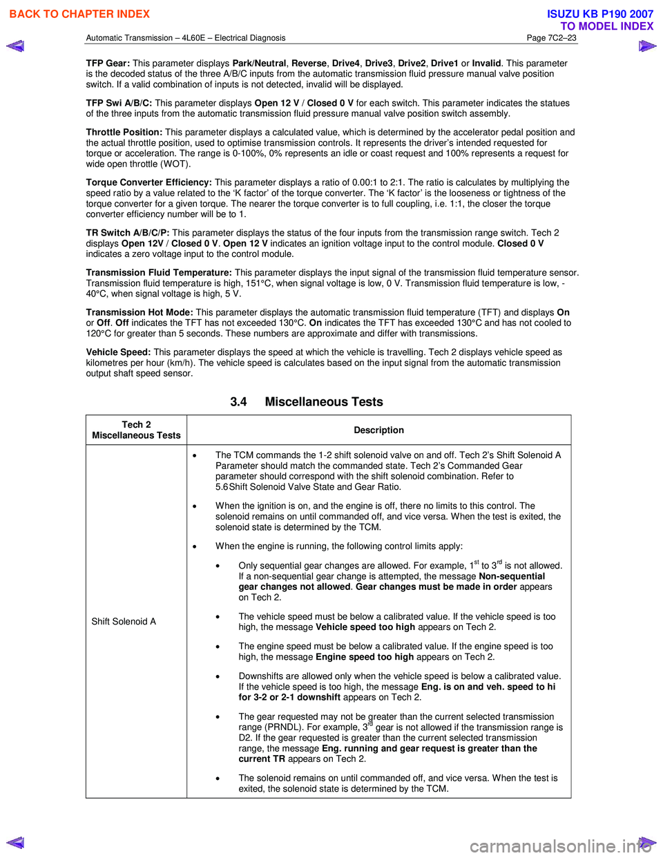
TFP Gear: This parameter displays Park/Neutral, Reverse , Drive4 , Drive3 , Drive2 , Drive1 or Invalid . This parameter
is the decoded status of the three A/B/C inputs from the automatic transmission fluid pressure manual valve position
switch. If a valid combination of inputs is not detected, invalid will be displayed.
TFP Swi A/B/C: This parameter displays Open 12 V / Closed 0 V for each switch. This parameter indicates the statues
of the three inputs from the automatic transmission fluid pressure manual valve position switch assembly.
Throttle Position: This parameter displays a calculated value, which is determined by the accelerator pedal position and
the actual throttle position, used to optimise transmission controls. It represents the driver’s intended requested for
torque or acceleration. The range is 0-100%, 0% represents an idle or coast request and 100% represents a request for
wide open throttle (WOT).
Torque Converter Efficiency: This parameter displays a ratio of 0.00:1 to 2:1. The ratio is calculates by multiplying the
speed ratio by a value related to the ‘K factor’ of the torque converter. The ‘K factor’ is the looseness or tightness of the
torque converter for a given torque. The nearer the torque converter is to full coupling, i.e. 1:1, the closer the torque
converter efficiency number will be to 1.
TR Switch A/B/C/P: This parameter displays the status of the four inputs from the transmission range switch. Tech 2
displays Open 12V / Closed 0 V . Open 12 V indicates an ignition voltage input to the control module. Closed 0 V
indicates a zero voltage input to the control module.
Transmission Fluid Temperature: This parameter displays the input signal of the transmission fluid temperature sensor.
Transmission fluid temperature is high, 151°C, when signal voltage is low, 0 V. Transmission fluid temperature is low, -
40°C, when signal voltage is high, 5 V.
Transmission Hot Mode: This parameter displays the automatic transmission fluid temperature (TFT) and displays On
or Off . Off indicates the TFT has not exceeded 130°C. On indicates the TFT has exceeded 130°C and has not cooled to
120°C for greater than 5 seconds. These numbers are approximate and differ with transmissions.
Vehicle Speed: This parameter displays the speed at which the vehicle is travelling. Tech 2 displays vehicle speed as
kilometres per hour (km/h). The vehicle speed is calculates based on the input signal from the automatic transmission
output shaft speed sensor.
3.4 Miscellaneous Tests
Tech 2
Miscellaneous Tests Description
Shift Solenoid A •
The TCM commands the 1-2 shift solenoid valve on and off. Tech 2’s Shift Solenoid A
Parameter should match the commanded state. Tech 2’s Commanded Gear
parameter should correspond with the shift solenoid combination. Refer to
5.6 Shift Solenoid Valve State and Gear Ratio.
• When the ignition is on, and the engine is off, there no limits to this control. The
solenoid remains on until commanded off, and vice versa. W hen the test is exited, the
solenoid state is determined by the TCM.
• W hen the engine is running, the following control limits apply:
• Only sequential gear changes are allowed. For example, 1
st to 3rd is not allowed.
If a non-sequential gear change is attempted, the message Non-sequential
gear changes not allowed . Gear changes must be made in order appears
on Tech 2.
• The vehicle speed must be below a calibrated value. If the vehicle speed is too
high, the message Vehicle speed too high appears on Tech 2.
• The engine speed must be below a calibrated value. If the engine speed is too
high, the message Engine speed too high appears on Tech 2.
• Downshifts are allowed only when the vehicle speed is below a calibrated value.
If the vehicle speed is too high, the message Eng. is on and veh. speed to hi
for 3-2 or 2-1 downshift appears on Tech 2.
• The gear requested may not be greater than the current selected transmission
range (PRNDL). For example, 3
rd gear is not allowed if the transmission range is
D2. If the gear requested is greater than the current selected transmission
range, the message Eng. running and gear request is greater than the
current TR appears on Tech 2.
• The solenoid remains on until commanded off, and vice versa. W hen the test is
exited, the solenoid state is determined by the TCM.
BACK TO CHAPTER INDEX
TO MODEL INDEX
ISUZU KB P190 2007
Page 3812 of 6020
Automatic Transmission – 4L60E – Electrical Diagnosis Page 7C2–26
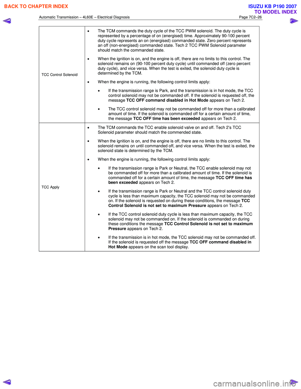
TCC Control Solenoid
• The TCM commands the duty cycle of the TCC PWM solenoid. The duty cycle is
represented by a percentage of on (energised) time. Approximately 90-100 percent
duty cycle represents an on (energised) commanded state. Zero percent represents
an off (non-energised) commanded state. Tech 2 TCC PW M Solenoid parameter
should match the commanded state.
• When the ignition is on, and the engine is off, there are no limits to this control. The
solenoid remains on (90-100 percent duty cycle) until commanded off (zero percent
duty cycle), and vice versa. When the test is exited, the solenoid duty cycle is
determined by the TCM.
• W hen the engine is running, the following control limits apply:
• If the transmission range is Park, and the transmission is in hot mode, the TCC
control solenoid may not be commanded off. If the solenoid is requested off, the
message TCC OFF command disabled in Hot Mode appears on Tech 2.
• The TCC control solenoid may not be commanded off for more than a calibrated
amount of time. If the solenoid is commanded off for a certain amount of time,
the message TCC OFF time has been exceeded appears on Tech 2.
TCC Apply
•
The TCM commands the TCC enable solenoid valve on and off. Tech 2’s TCC
Solenoid parameter should match the commended state.
• When the ignition is on, and the engine is off, there are no limits to this control. The
solenoid remains on until commanded off, and vice versa. W hen the test is exited, the
solenoid state is determined by the TCM.
• W hen the engine is running, the following control limits apply:
• If the transmission range is Park or Neutral, the TCC enable solenoid may not
be commanded off for more than a calibrated amount of time. If the solenoid is
commanded off for a certain amount of time, the message TCC OFF time has
been exceeded appears on Tech 2.
• If the transmission range is Park or Neutral and the TCC control solenoid duty
cycle is less than maximum capacity, the TCC solenoid may not be commanded
on. If the solenoid is requested on during these conditions, the message TCC
Control Solenoid is not set to maximum Pressure appears on Tech 2.
• If the TCC control solenoid duty cycle is less than maximum capacity, the TCC
solenoid may not be commanded on. If the solenoid is commanded on during
these conditions the message TCC Control Solenoid is not set to maximum
Pressure appears on Tech 2.
• If the transmission is in hot mode, the TCC solenoid may not be commanded off.
If the solenoid is requested off the message TCC OFF command disabled in
Hot Mode appears on the scan tool display.
BACK TO CHAPTER INDEX
TO MODEL INDEX
ISUZU KB P190 2007
Page 3815 of 6020
Automatic Transmission – 4L60E – Electrical Diagnosis Page 7C2–29
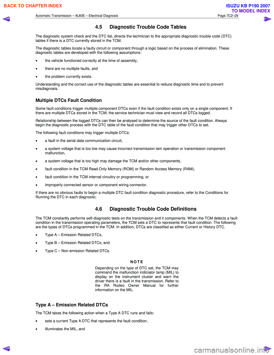
4.5 Diagnostic Trouble Code Tables
The diagnostic system check and the DTC list, directs the technician to the appropriate diagnostic trouble code (DTC)
tables if there is a DTC currently stored in the TCM.
The diagnostic tables locate a faulty circuit or component through a logic based on the process of elimination. These
diagnostic tables are developed with the following assumptions:
• the vehicle functioned correctly at the time of assembly,
• there are no multiple faults, and
• the problem currently exists.
Understanding and the correct use of the diagnostic tables are essential to reduce diagnostic time and to prevent
misdiagnosis.
Multiple DTCs Fault Condition
Some fault conditions trigger multiple component DTCs even if the fault condition exists only on a single component. If
there are multiple DTCs stored in the TCM, the service technician must view and record all DTCs logged.
Relationship between the logged DTCs can then be analysed to determine the source of the fault condition. Always
begin the diagnostic process with the DTC table of the fault condition that may trigger other DTCs to set.
The following fault conditions may trigger multiple DTCs:
• a fault in the serial data communication circuit,
• a system voltage that is too low may cause incorrect transmission tem operation or transmission component
malfunction,
• a system voltage that is too high may damage the TCM and/or other components,
• fault condition in the TCM Read Only Memory (ROM) or Random Access Memory (RAM),
• fault condition in the TCM internal circuitry or programming, or
• improperly connected sensor or component wiring connector.
If there are no obvious faults to begin a multiple DTC fault condition diagnostic procedure, refer to the Conditions for
Running the DTC in each diagnostic.
4.6 Diagnostic Trouble Code Definitions
The TCM constantly performs self-diagnostic tests on the transmission and it components. W hen the TCM detects a fault
condition in the transmission operating parameters, the TCM sets a DTC to represents that fault condition. The following
are the types of DTCs programmed in the TCM. In addition, DTCs are classified as either Current or History DTC.
• Type A – Emission Related DTCs,
• Type B – Emission Related DTCs, and
• Type C – Non-emission Related DTCs.
NOTE
Depending on the type of DTC set, the TCM may
command the malfunction indiciator lamp (MIL) to
display on the instrument cluster and warn the
driver there is a fault in the transmission. Refer to
the RA Rodeo Owner Manual for further
information on the MIL.
Type A – Emission Related DTCs
The TCM takes the following action when a Type A DTC runs and fails:
• sets a current Type A DTC that represents the fault condition,
• illuminates the MIL, and
BACK TO CHAPTER INDEX
TO MODEL INDEX
ISUZU KB P190 2007
Page 3817 of 6020
Automatic Transmission – 4L60E – Electrical Diagnosis Page 7C2–31
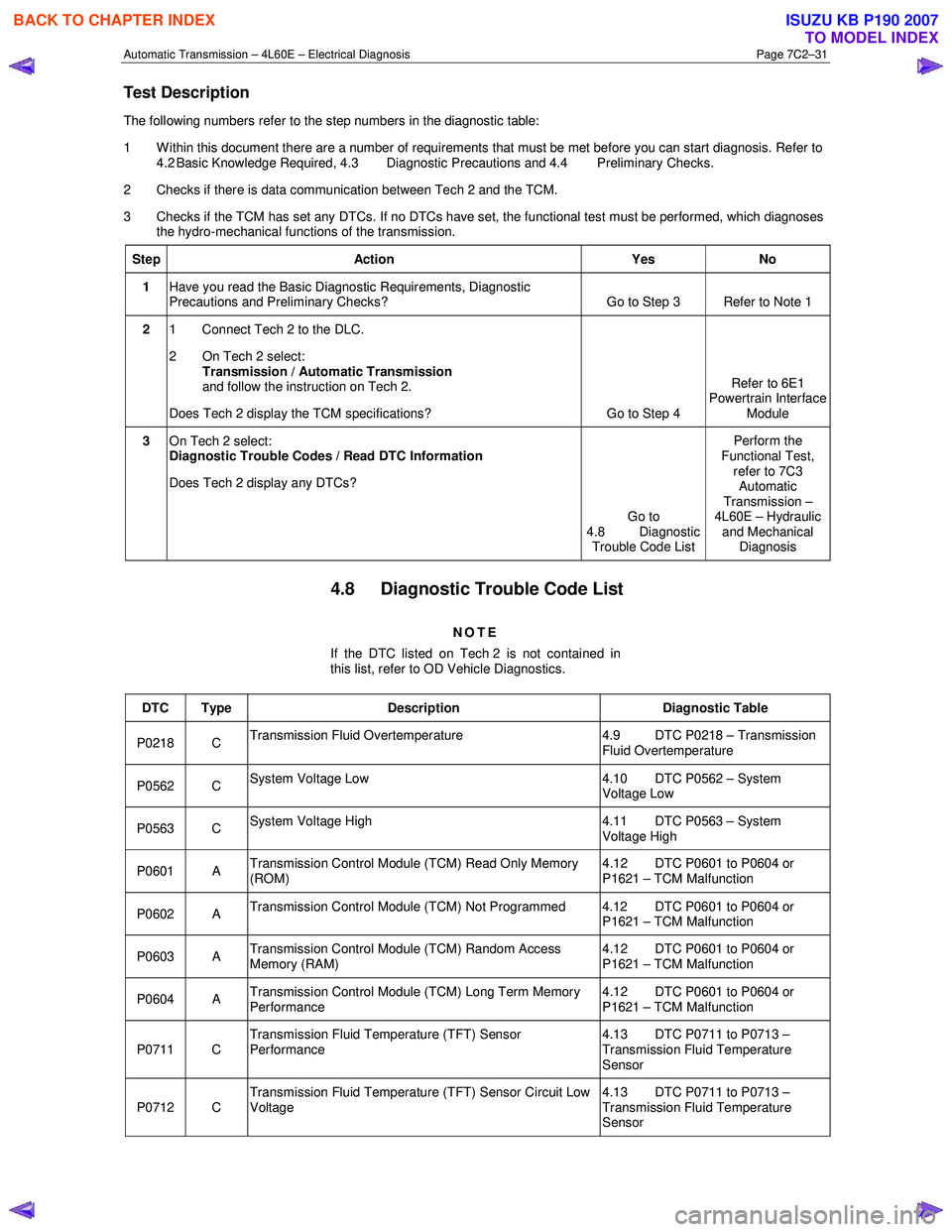
Test Description
The following numbers refer to the step numbers in the diagnostic table:
1 Within this document there are a number of requirements that must be met before you can start diagnosis. Refer to 4.2 Basic Knowledge Required, 4.3 Diagnostic Precautions and 4.4 Preliminary Checks.
2 Checks if there is data communication between Tech 2 and the TCM.
3 Checks if the TCM has set any DTCs. If no DTCs have set, the functional test must be performed, which diagnoses the hydro-mechanical functions of the transmission.
Step Action Yes No
1 Have you read the Basic Diagnostic Requirements, Diagnostic
Precautions and Preliminary Checks? Go to Step 3 Refer to Note 1
2
1 Connect Tech 2 to the DLC.
2 On Tech 2 select: Transmission / Automatic Transmission
and follow the instruction on Tech 2.
Does Tech 2 display the TCM specifications? Go to Step 4 Refer to 6E1
Powertrain Interface
Module
3 On Tech 2 select:
Diagnostic Trouble Codes / Read DTC Information
Does Tech 2 display any DTCs?
Go to
4.8 Diagnostic Trouble Code List Perform the
Functional Test, refer to 7C3 Automatic
Transmission –
4L60E – Hydraulic and Mechanical Diagnosis
4.8 Diagnostic Trouble Code List
NOTE
If the DTC listed on Tech 2 is not contained in
this list, refer to OD Vehicle Diagnostics.
DTC Type Description Diagnostic Table
P0218 C Transmission Fluid Overtemperature 4.9 DTC P0218 – Transmission
Fluid Overtemperature
P0562 C System Voltage Low 4.10 DTC P0562 – System
Voltage Low
P0563 C System Voltage High 4.11 DTC P0563 – System
Voltage High
P0601 A Transmission Control Module (TCM) Read Only Memory
(ROM) 4.12 DTC P0601 to P0604 or
P1621 – TCM Malfunction
P0602 A Transmission Control Module (TCM) Not Programmed 4.12 DTC P0601 to P0604 or
P1621 – TCM Malfunction
P0603 A Transmission Control Module (TCM) Random Access
Memory (RAM) 4.12 DTC P0601 to P0604 or
P1621 – TCM Malfunction
P0604 A Transmission Control Module (TCM) Long Term Memory
Performance 4.12 DTC P0601 to P0604 or
P1621 – TCM Malfunction
P0711 C Transmission Fluid Temperature (TFT) Sensor
Performance 4.13 DTC P0711 to P0713 –
Transmission Fluid Temperature
Sensor
P0712 C Transmission Fluid Temperature (TFT) Sensor Circuit Low
Voltage 4.13 DTC P0711 to P0713 –
Transmission Fluid Temperature
Sensor
BACK TO CHAPTER INDEX
TO MODEL INDEX
ISUZU KB P190 2007
Page 3821 of 6020
Automatic Transmission – 4L60E – Electrical Diagnosis Page 7C2–35
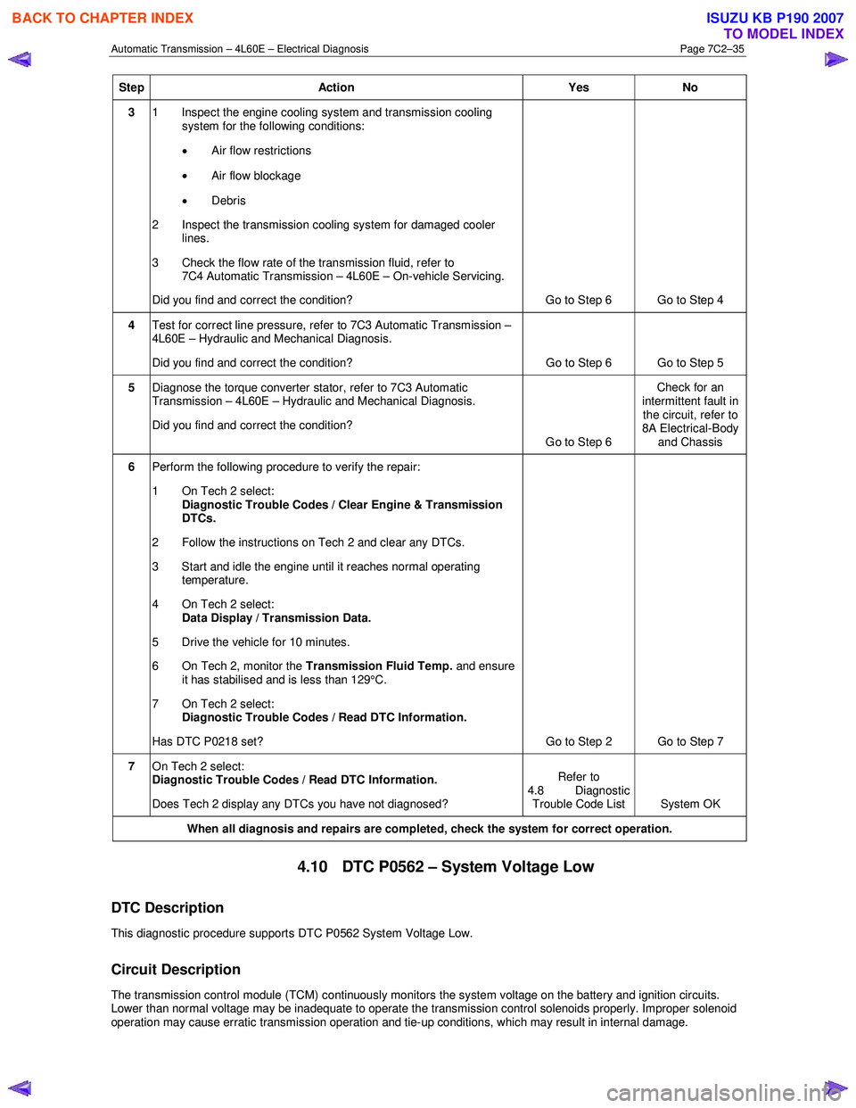
Step Action Yes No
3 1 Inspect the engine cooling system and transmission cooling
system for the following conditions:
• Air flow restrictions
• Air flow blockage
• Debris
2 Inspect the transmission cooling system for damaged cooler lines.
3 Check the flow rate of the transmission fluid, refer to 7C4 Automatic Transmission – 4L60E – On-vehicle Servicing.
Did you find and correct the condition? Go to Step 6 Go to Step 4
4 Test for correct line pressure, refer to 7C3 Automatic Transmission –
4L60E – Hydraulic and Mechanical Diagnosis.
Did you find and correct the condition? Go to Step 6 Go to Step 5
5 Diagnose the torque converter stator, refer to 7C3 Automatic
Transmission – 4L60E – Hydraulic and Mechanical Diagnosis.
Did you find and correct the condition? Go to Step 6 Check for an
intermittent fault in the circuit, refer to
8A Electrical-Body
and Chassis
6 Perform the following procedure to verify the repair:
1 On Tech 2 select: Diagnostic Trouble Codes / Clear Engine & Transmission
DTCs.
2 Follow the instructions on Tech 2 and clear any DTCs.
3 Start and idle the engine until it reaches normal operating temperature.
4 On Tech 2 select: Data Display / Transmission Data.
5 Drive the vehicle for 10 minutes.
6 On Tech 2, monitor the Transmission Fluid Temp. and ensure
it has stabilised and is less than 129°C.
7 On Tech 2 select:
Diagnostic Trouble Codes / Read DTC Information.
Has DTC P0218 set? Go to Step 2 Go to Step 7
7 On Tech 2 select:
Diagnostic Trouble Codes / Read DTC Information.
Does Tech 2 display any DTCs you have not diagnosed? Refer to
4.8 Diagnostic Trouble Code List System OK
When all diagnosis and repairs are completed, check the
system for correct operation.
4.10 DTC P0562 – System Voltage Low
DTC Description
This diagnostic procedure supports DTC P0562 System Voltage Low.
Circuit Description
The transmission control module (TCM) continuously monitors the system voltage on the battery and ignition circuits.
Lower than normal voltage may be inadequate to operate the transmission control solenoids properly. Improper solenoid
operation may cause erratic transmission operation and tie-up conditions, which may result in internal damage.
BACK TO CHAPTER INDEX
TO MODEL INDEX
ISUZU KB P190 2007
Page 3822 of 6020
Automatic Transmission – 4L60E – Electrical Diagnosis Page 7C2–36
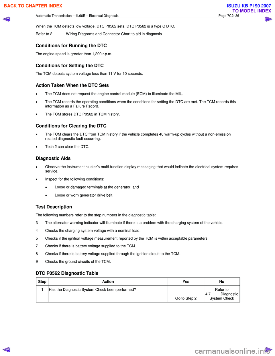
When the TCM detects low voltage, DTC P0562 sets. DTC P0562 is a type C DTC.
Refer to 2 W iring Diagrams and Connector Chart to aid in diagnosis.
Conditions for Running the DTC
The engine speed is greater than 1,200 r.p.m.
Conditions for Setting the DTC
The TCM detects system voltage less than 11 V for 10 seconds.
Action Taken When the DTC Sets
• The TCM does not request the engine control module (ECM) to illuminate the MIL.
• The TCM records the operating conditions when the conditions for setting the DTC are met. The TCM records this
information as a Failure Record.
• The TCM stores DTC P0562 in TCM history.
Conditions for Clearing the DTC
• The TCM clears the DTC from TCM history if the vehicle completes 40 warm-up cycles without a non-emission
related diagnostic fault occurring.
• Tech 2 can clear the DTC.
Diagnostic Aids
• Observe the instrument cluster’s multi-function display messaging that would indicate the electrical system requires
service.
• Inspect for the following conditions:
• Loose or damaged terminals at the generator, and
• Loose or worn generator drive belt.
Test Description
The following numbers refer to the step numbers in the diagnostic table:
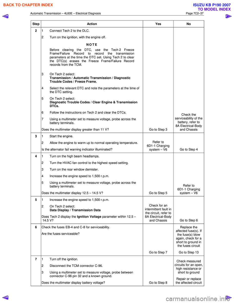
3 The alternator warning indicator will illuminate if there is a problem with the charging system of the vehicle.
4 Checks the charging system voltage with a nominal load.
5 Checks if the ignition voltage measurement reported by the TCM is within acceptable parameters.
7 Checks if there is battery voltage supplied to the TCM.
8 Checks if there is battery voltage supplied through the ignition circuit to the TCM.
9 Checks the ground circuits of the TCM.
DTC P0562 Diagnostic Table
Step Action Yes No
1 Has the Diagnostic System Check been performed?
Go to Step 2 Refer to
4.7 Diagnostic
System Check
BACK TO CHAPTER INDEX
TO MODEL INDEX
ISUZU KB P190 2007
Page 3823 of 6020
Automatic Transmission – 4L60E – Electrical Diagnosis Page 7C2–37
Step Action Yes No
2 1 Connect Tech 2 to the DLC.
2 Turn on the ignition, with the engine off.
NOTE
Before clearing the DTC, use the Tech 2 Freeze
Frame/Failure Record to record the transmission
parameters at the time the DTC set. Using Tech 2 to clear
the DTC(s) erases the Freeze Frame/Failure Record
records from the TCM.
3 On Tech 2 select: Transmission / Automatic Transmission / Diagnostic
Trouble Codes / Freeze Frame.
4 Select the relevant DTC and note the parameters at the time of the DTC setting.
5 On Tech 2 select:
Diagnostic Trouble Codes / Clear Engine & Transmission
DTCs.
6 Follow the instructions on Tech 2 and clear the DTCs.
7 Using a multimeter set to measure voltage, probe across the battery terminals.
Does the multimeter display greater than 11 V? Go to Step 3 Check the
serviceability of the battery, refer to
8A Electrical-Body and Chassis
3 1 Start the engine.
2 Allow the engine to warm up to normal operating temperature.
Is the alternator fail warning indicator illuminated? Refer to
6D1-1 Charging system – V6 Go to Step 4
4 1 Turn on the high beam headlamps.
2 Turn the HVAC fan control to the highest speed setting.
3 Turn on the rear window demister.
4 Increase the engine speed to 1,500 r.p.m.
5 Using a multimeter set to measure voltage, probe across the battery terminals.
Does the multimeter display 12.5 – 14.5 V? Go to Step 5 Refer to
6D1-1 Charging system – V6
5 1 Increase the engine speed to 1,500 r.p.m.
2 On Tech 2 select: Data Display / Transmission Data
Does Tech 2 display the Ignition Voltage parameter within 12.5 –
14.5 V? Check for an
intermittent fault in the circuit, refer to
8A Electrical-Body
and Chassis Go to Step 6
6
Check the fuses EB-4 and C-8 for serviceability.
Are the fuses serviceable?
Go to Step 7 Replace the
affected fuse(s). If the fuse(s) blow
again, check for a short to ground in the fuses circuit
Go to Step 13
7 1 Turn off the ignition.
2 Disconnect the TCM connector C-96.
3 Using a multimeter set to measure voltage, probe between connector C-96 pin 32 and a known ground.
Does the multimeter display battery voltage? Go to Step 8 Check measured
circuits for an open,
high resistance or short to ground
Repair or replace
the affected circuit
BACK TO CHAPTER INDEX
TO MODEL INDEX
ISUZU KB P190 2007