display ISUZU KB P190 2007 Workshop Repair Manual
[x] Cancel search | Manufacturer: ISUZU, Model Year: 2007, Model line: KB P190, Model: ISUZU KB P190 2007Pages: 6020, PDF Size: 70.23 MB
Page 3767 of 6020

Automatic Transmission – 4L60E – General Information Page 7C1–7
Figure 7C1 – 1
Legend
1 Model year
2 Broad Cast Code Identifier
3 Manufacturer Source Code 4 Julian Date
5 Shift Build 6 Individual Transmission Serial Number
7 Identification Stamping Location
2.3 Economy, Power and Cruise Modes
The programming in the transmission control module (TCM) allows for different shift patterns, which are driver
controllable through the use of the power (PWR) button. The power button is located in the centre console.
Economy Mode
The calibration for this mode is for maximum comfort, with minimal intrusion of engine noise and smooth shifts under all
driving conditions. When additional power is required for acceleration, full throttle upshifts are similar to those calibrated
for the power mode.
Power Mode
When activated, the TCM modifies the transmission calibration in the following ways:
1 When the throttle is less than 80% open, later upshift points are provided.
2 Shift time is reduced.
3 The torque converter clutch (TCC) will be applied in both the third and fourth speed ranges.
Cruise Mode
When the driver activates the cruise control (where fitted), the power icon in the instrument clusters multi-function display
(MFD) will be deactivated (provided the vehicle was operating in power mode) and the transmission shift pattern will
switch to the cruise control pattern. When in this mode, the TCM modifies the shift pattern so that earlier downshift and
later upshift points are provided.
Through the electronic programming of the logic processes contained in the TCM, the frequency of gear shifting and
torque converter clutch application and release is minimised. The end result of these logic processes, is that a quick
series of upshifts and downshifts (e.g. a '4 – 3 – 4' shift pattern) is minimised.
BACK TO CHAPTER INDEX
TO MODEL INDEX
ISUZU KB P190 2007
Page 3773 of 6020

Automatic Transmission – 4L60E – General Information Page 7C1–13
General Definition
Line Pressure The main fluid pressure in a hydraulic system created by the pump and pressure
regulator valve.
Manual Valve A spool valve that distributes fluid to various hydraulic circuits and is mechanically
linked to the gear selector lever.
Orifice A restricting device (usually a hole in the spacer plate) for controlling pressure build up
into another circuit.
Overdrive An operating condition in the gear set allowing output speed to be higher than input
speed and output torque to be lower than input torque.
Overrunning The function of a one-way mechanical clutch that allows the clutch to freewheel during certain operating conditions of the transmission.
Pedal Position The percentage angle of the accelerator pedal as displayed by Tech 2.
Pinion Gears Pinion gears (housed in a carrier) that are in constant mesh with a circumferential
internal gear and centralised sun gear.
Planetary Gear Set An assembly of gears that consists of an internal gear, planet pinion gears with a carrier, and a sun gear.
Pressure A measurable force that is exerted on an area and expressed as kilopascals (kPa).
Pulse Width Modulated (PW M) An electronic signal that continuously cycles the On and Off time of a device (such as
a solenoid) while varying the amount of On time.
Race (Inner or Outer) A highly polished steel surface that contacts bearings or sprag or roller elements.
Reduction (Gear Reduction) An operating condition in the gear set allowing output speed to be lower than input speed and output torque to be higher than input torque.
Residual Fluid Pressure Excess pressure contained within an area after the supply pressure has been terminated.
Roller Clutch A mechanical clutch (holding device) consisting of roller bearings assembled between inner and outer races.
Servo A spring loaded device consisting of a piston in a bore that is operated (stroked) by
hydraulic pressure to apply or release a band.
Spool Valve A round hydraulic control valve often containing a variety of land and valley diameters.
Sprag Clutch A mechanical clutch (holding device consisting of "figure eight" like elements
assembled between inner and outer races.
Staking The effect of deforming, peening over or riveting a shaft to provide a solid mounting.
Throttle Position The travel of the throttle plate that is expressed in percentages and measured by
Tech 2.
Torque A measurable twisting force expressed in terms of Newton metres (Nm).
Torque Converter A component of an automatic transmission, (attached to the engine flex plate) that
transfers torque from the engine to the transmission through a fluid coupling.
Torx Plus Bit A special tool used for the removal of the bell housing. Precision tip fit means that cam
out of the bolt head is virtually eliminated.
NOTE
Torx
Plus Bits are different from normal Torx
Bits
Transmission Control Module
(TCM) An electronic device that manages the vehicle's engine and automatic transmission
functions.
Variable Capacity Pump The device that provides fluid for operating the hydraulic circuits in the transmission. The amount of fluid supplied varies depending on vehicle operating conditions.
BACK TO CHAPTER INDEX
TO MODEL INDEX
ISUZU KB P190 2007
Page 3787 of 6020

Automatic Transmission – 4L60E – Electrical Diagnosis Page 7C2–1
7C2
Diagnosis
ATTENTION
Before performing any service operation or other procedure described in this Section, refer to 00 Warnings, Cautions and Notes for correct workshop practices with regard to safety and/or property damage.
1 General Information ............................................................................................................ ...................8
1.1 Introduction ............................................................................................................................................................ 8
1.2 General Description ............................................................................................................................................... 8
Transmission Adaptive Functions ................................................................................................ ....................... 9
Limp Home Mode Description ............................................................................................................................ 10
1.3 Transmission Indicators and Messages ............................................................................................................ 10
1.4 Electronic Component Description ............................................................................................... ..................... 10
Transmission Control Module (TCM) ................................................................................................................. 10
2 Wiring Diagrams and Connector Chart ............................................................................................ ..13
3 Tech 2 Information ...............................................................................................................................14
3.1 Tech 2 Diagnostics .............................................................................................................................................. 14
Test Modes ........................................................................................................................................................... 14
Diagnostic Trouble Codes ....................................................................................................... ......................... 14
Data Display ..................................................................................................................................................... 14
Snapshot .......................................................................................................................................................... 15
Additional Functions ........................................................................................................... .............................. 15
Miscellaneous Tests ......................................................................................................................................... 15
Programming.................................................................................................................................................... 16
3.2 Data Display ......................................................................................................................................................... 16
Transmission Data .............................................................................................................. ................................. 16
Transmission Data Parameters ................................................................................................... ..................... 16
TCC Data............................................................................................................................................................... 17
TCC Data Parameters ............................................................................................................ .......................... 17
1-2 Shift Data ........................................................................................................................................................ 18
1-2 Shift Data Parameters ................................................................................................................................ 18
2-3 Shift Data ........................................................................................................................................................ 18
2-3 Shift Data Parameters ................................................................................................................................ 18
3-4 Shift Data ........................................................................................................................................................ 19
3-4 Shift Data Parameters ................................................................................................................................ 19
3-2 Downshift Data............................................................................................................................................... 19
3-2 Downshift Data Parameters ....................................................................................................................... 19
Pressure Control Solenoid Data ................................................................................................. ........................ 19
Pressure Control Solenoid Data Parameters ...................................................................................... ............. 20
Transmission Adapts .......................................................................................................................................... 20
1-2 Adapt Data ................................................................................................................................................. 20
2-3 Adapt Data ................................................................................................................................................. 20
3-4 Adapt Data ................................................................................................................................................. 20
Steady State Adapt Data ........................................................................................................ .......................... 21
3.3 Tech 2 Data Definitions ........................................................................................................ ............................... 21
3.4 Miscellaneous Tests ............................................................................................................................................ 23
Automatic Tra nsm ission – 4L60E – Electric al
BACK TO CHAPTER INDEX
TO MODEL INDEX
ISUZU KB P190 2007
Page 3796 of 6020

Automatic Transmission – 4L60E – Electrical Diagnosis Page 7C2–10
Limp Home Mode Description
If a major electrical system failure occurs which could affect vehicle safety or damage the transmission during normal
operation, the TCM enters a limp home mode. In the limp home mode, the transmission operates in the following
manner:
• The pressure control solenoid is off and the line pressure is at maximum to minimise clutch slippage.
• The TCC solenoid is off, therefore the torque converter clutch is disabled.
• The two shift solenoids are turned off. The transmission will operate in fourth gear if the vehicle has successfully
completed a 1-2 upshift in the current ignition cycle. If the vehicle has not completed a 1-2 upshift in the current
ignition cycle, the transmission will operate in third gear. If the transmission is operating in fourth gear, third gear
may be obtained if the engine is stopped briefly and re-started.
In limp home mode, the gear selector lever is ineffective at selecting forward gear ranges. In third or fourth gear, heat
builds up in the transmission quickly, particularly in stop and go traffic. Excessive heat build-up may cause transmission
failure if the vehicle is driven for extended distances in limp home mode.
1.3 Transmission Indicators and Messages
For information pertaining to the instrument cluster and the transmission information it displays, refer to the RA Rodeo
Owner Handbook.
1.4 Electronic Component Description
For all other electrical components not covered in this section, refer to General Motors Powertrain Group Electronically
Controlled Automatic Transmission Technician's Guide.
Transmission Control Module (TCM)
The Transmission Control Module (TCM) is located under the instrument panel, next to the brake pedal assembly and
connects directly to the transmission wiring harness. A single 49-way connector is used to make the connection between
the vehicle wiring harness and the TCM.
To access the connector for diagnosis:
1 Ensure the ignition switch is in the OFF position.
2 Disconnect the connector (1) from the transmission control module (TCM) (2) as follows, refer to Figure 7C2 – 2: a remove the securing pin (3),
b press the locking tab and swing the lever (4) to free the connector,
c remove the connector.
BACK TO CHAPTER INDEX
TO MODEL INDEX
ISUZU KB P190 2007
Page 3800 of 6020

Automatic Transmission – 4L60E – Electrical Diagnosis Page 7C2–14
3 Tech 2 Information
3.1 Tech 2 Diagnostics
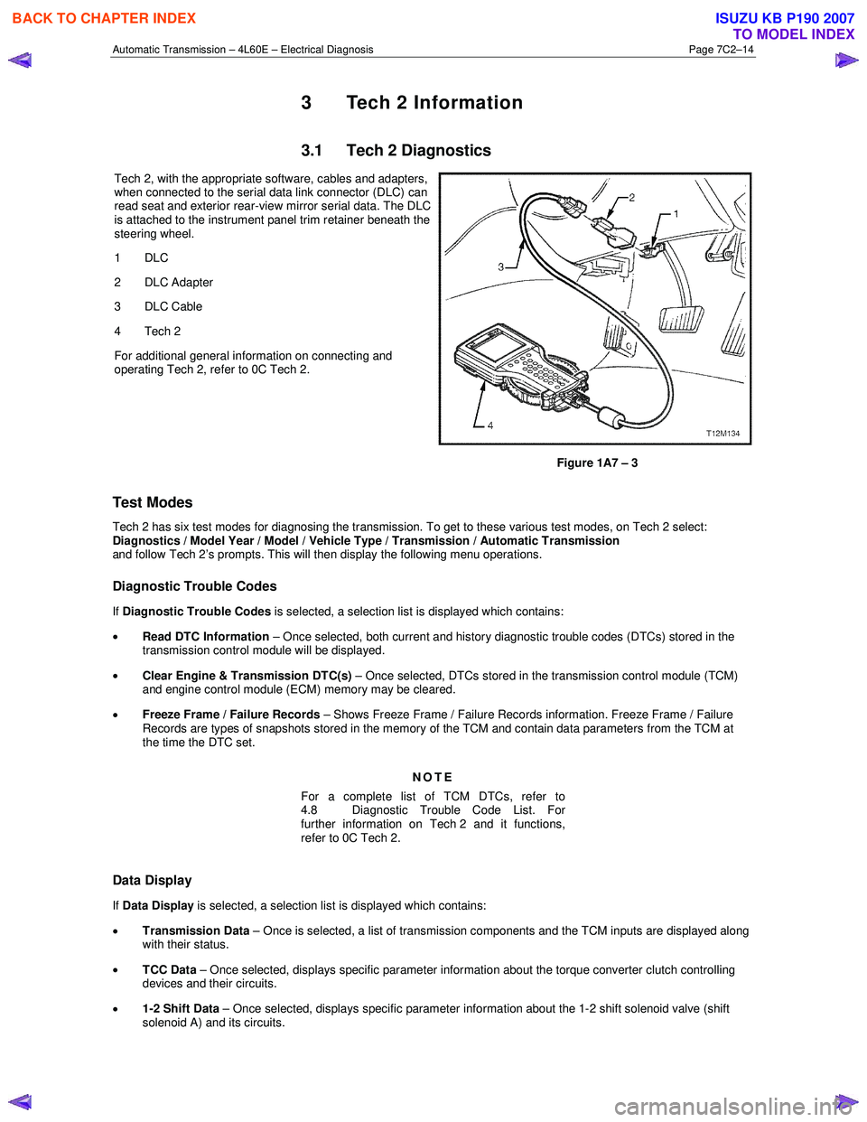
Tech 2, with the appropriate software, cables and adapters,
when connected to the serial data link connector (DLC) can
read seat and exterior rear-view mirror serial data. The DLC
is attached to the instrument panel trim retainer beneath the
steering wheel.
1 DLC
2 DLC Adapter
3 DLC Cable
4 Tech 2
For additional general information on connecting and
operating Tech 2, refer to 0C Tech 2.
Figure 1A7 – 3
Test Modes
Tech 2 has six test modes for diagnosing the transmission. To get to these various test modes, on Tech 2 select:
Diagnostics / Model Year / Model / Vehicle Type / Transmission / Automatic Transmission
and follow Tech 2’s prompts. This will then display the following menu operations.
Diagnostic Trouble Codes
If Diagnostic Trouble Codes is selected, a selection list is displayed which contains:
• Read DTC Information – Once selected, both current and history diagnostic trouble codes (DTCs) stored in the
transmission control module will be displayed.
• Clear Engine & Transmission DTC(s) – Once selected, DTCs stored in the transmission control module (TCM)
and engine control module (ECM) memory may be cleared.
• Freeze Frame / Failure Records – Shows Freeze Frame / Failure Records information. Freeze Frame / Failure
Records are types of snapshots stored in the memory of the TCM and contain data parameters from the TCM at
the time the DTC set.
NOTE
For a complete list of TCM DTCs, refer to
4.8 Diagnostic Trouble Code List. For
further information on Tech 2 and it functions,
refer to 0C Tech 2.
Data Display
If Data Display is selected, a selection list is displayed which contains:
• Transmission Data – Once is selected, a list of transmission components and the TCM inputs are displayed along
with their status.
• TCC Data – Once selected, displays specific parameter information about the torque converter clutch controlling
devices and their circuits.
• 1-2 Shift Data – Once selected, displays specific parameter information about the 1-2 shift solenoid valve (shift
solenoid A) and its circuits.
BACK TO CHAPTER INDEX
TO MODEL INDEX
ISUZU KB P190 2007
Page 3801 of 6020

Automatic Transmission – 4L60E – Electrical Diagnosis Page 7C2–15
• 2-3 Shift Data – Once this mode is selected, displays specific parameter information about the 2-3 shift solenoid
valve (shift solenoid B) and its circuits.
• 3-4 Shift Data – Once selected, displays information on 3-4 shift timing.
• 3-2 Downshift Data – Once selected, displays information on 3-2 downshift timing.
• Pressure Control Solenoid Data – Once selected, displays specific parameter information about the PC solenoid
and its circuits.
• Transmission Adapts – Once selected, it has further sub menus:
• 1-2 Adapt Data – In this mode Tech 2 continuously monitors and displays 1-2 TAP cell data parameters.
• 2-3 Adapt Data –In this mode Tech 2 continuously monitors and displays 2-3 TAP cell data parameters.
• 3-4 Adapt Data –In this mode Tech 2 continuously monitors and displays 3-4 TAP cell data parameters.
• Steady State Adapt Data – In this mode Tech 2 continuously monitors and displays Steady State TAP data
parameters.
• System Identification: In this mode, Tech 2 will display the transmission identification screen. The following items
will be displayed; Identifier, Partnumber, Hardware Partnumber, Alpha Code, Software Version Number, Software
Partnumber, VIN Digit 1-10, VIN Digit 11-17.
NOTE
Further information about the Data Display mode
and the data parameter is contained in
3.2 Data Display.
Snapshot
In this test mode, Tech 2 captures TCM data before and after a forced manual trigger.
Additional Functions
If Additional Functions is selected, a selections list is displayed which contains:
• System Identification – In this mode, Tech 2 will display the transmission identification screen. The following items
will be displayed; Identifier, Partnumber, Hardware Partnumber, Alpha Code, Software Version Number, Software
Partnumber.
Miscellaneous Tests
If Miscellaneous Functions is selected, a selections list is displayed which contains:
• TCC Solenoid –Tech 2 can command the TCC solenoid on and off. Tech 2 will display whether the TCC solenoid
is active or inactive.
• TCC PWN Solenoid – Tech 2 can command the TCC PWM solenoid on and off. Tech 2 will display whether the
TCC PWM solenoid is active or inactive and torque percentage.
• TCC Apply – Tech 2 can command the TCC on when the vehicle is above 50 km/h.
• Shift Solenoid A – Tech 2 can command the shift solenoid A (1-2 shift solenoid) on and off.
• Shift Solenoid B – Tech 2 can command the shift solenoid B (2-3 shift solenoid) on and off.
• 3/2 Downshift Solenoid – Tech 2 can command the 3/2 downshift solenoid (3-2 shift solenoid) on and off.
• Gear Control – Tech 2 can incrementally command shift solenoid states to correspond to relative gear states. The
TCM will only allow single shift increments or decrements and does not allow a shift if it causes the engine RPM to
exceed a calibrated limit.
• Pressure Control Solenoid – This function allows the user to control state of the pressure control solenoid in
increments of 100 mA.
NOTE
For operating parameters of the
Miscellaneous Test, refer to 3.4 Miscellaneous Tests.
BACK TO CHAPTER INDEX
TO MODEL INDEX
ISUZU KB P190 2007
Page 3802 of 6020

Automatic Transmission – 4L60E – Electrical Diagnosis Page 7C2–16
Programming
If Programming is selected, a selection list is displayed which contains:
• Reset TAP Cells – This test allows the user to reset the Transmission Adapt (TAP) cells by pressing the Reset soft
key.
NOTE
Upon resetting the TAP cells the TCM loses all
learnt adaptive functions. When the vehicle is first
driven after this, the shifts may be harsh. This
harshness will ease as the TCM relearns the TAP
cells.
3.2 Data Display
If Data Display is selected, a selection list is displayed which contains the following:
Transmission Data
Once this mode, a list of transmission components and the TCM inputs are displayed along with their status.
Transmission Data Parameters
For definitions of the parameters in this table, refer to 3.3 Tech 2 Data Definitions.
Tech 2 Parameter Units Displayed Typical Data Value
Engine Torque Nm Varies
Throttle Position Percent Varies
Engine Speed RPM Varies
AT Input Speed N/A N/A
AT Output Speed RPM Varies
Vehicle Speed km/h 0
Commanded Gear 1,2,3,4 1
Shift Solenoid A On / Off Varies
Shift Solenoid B On / Off Varies
3-2 Downshift Solenoid On/Off On
Estimated Gear Ratio Ratio 8.00:1
Speed Ratio Ratio 8.00:1
Torque Converter Efficiency Ratio .00:1
TFP Switch A Open 12 V / Closed 0 V Varies
TFP Switch B Open 12 V / Closed 0 V Varies
TFP Switch C Open 12 V / Closed 0 V Varies
Engine Coolant Temperature °C Varies
Transmission Fluid Temp °C Varies
Transmission Hot Mode On/Off Off
PCS Actual Current Amps Varies (0.1 – 1.1 A)
PCS Desired Current Amps Varies (0.1 – 1.1 A)
PCS Duty Cycle Percent Varies
BACK TO CHAPTER INDEX
TO MODEL INDEX
ISUZU KB P190 2007
Page 3803 of 6020

Automatic Transmission – 4L60E – Electrical Diagnosis Page 7C2–17
Tech 2 Parameter Units Displayed Typical Data Value
High Side Driver 1 N/A N/A
TCC Solenoid On / Off Varies
TCC PWM Solenoid Percent 0%
TCC Slip Speed RPM +/-50 RPM from Engine Speed
Transmission Range (TR) Park/Neutral, Reverse, Drive4,
Drive3, Drive2, Drive1 or Invalid Park/Neutral
TR Switch A
Open 12 V / Closed 0 V Varies
TR Switch B Open 12 V / Closed 0 V Varies
TR Switch C Open 12 V / Closed 0 V Varies
TR Switch P Open 12 V / Closed 0 V Varies
Latest Shift Seconds Varies
1-2 Shift Time Seconds Varies
2-3 Shift Time Seconds Varies
3-4 Shift Time Seconds Varies
Cruise Control Active / Inactive Varies
A/C Clutch On / Off Varies
Ignition Voltage Volts 12-14 V
Shift Pattern Normal / Power / Cruise Varies
4 Wheel Drive Low Active / Inactive Inactive
TCC Data
Once this mode is selected, displays specific parameter information about the torque converter clutch controlling devices
and their circuits.
TCC Data Parameters
For definitions of the parameters in this table, refer to 3.3 Tech 2 Data Definitions.
Tech 2 Parameter Units Displayed Typical Data Value
TCC Solenoid On / Off Varies
TCC PWM Solenoid Percent 0%
TCC Slip Speed RPM +/-50 RPM from Engine Speed
TCC Duty Cycle Circuit Open or Shorted / Short to Battery /
Okay Okay
Throttle Position
Percent Varies
Engine Speed RPM Varies
AT Input Speed N/A N/A
AT Output Speed RPM Varies
Engine Torque Nm Varies
Vehicle Speed km/h 0
Commanded Gear 1,2,3,4 1
Engine Coolant Temperature °C Varies
BACK TO CHAPTER INDEX
TO MODEL INDEX
ISUZU KB P190 2007
Page 3804 of 6020

Automatic Transmission – 4L60E – Electrical Diagnosis Page 7C2–18
Tech 2 Parameter Units Displayed Typical Data Value
Transmission Fluid Temp °C Varies
Estimated Gear Ratio Ratio 8.00:1
Transmission Hot Mode On / Off Off
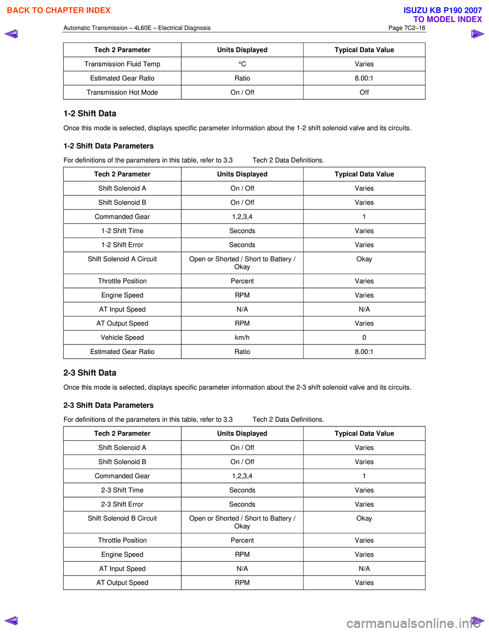
1-2 Shift Data
Once this mode is selected, displays specific parameter information about the 1-2 shift solenoid valve and its circuits.
1-2 Shift Data Parameters
For definitions of the parameters in this table, refer to 3.3 Tech 2 Data Definitions.
Tech 2 Parameter Units Displayed Typical Data Value
Shift Solenoid A On / Off Varies
Shift Solenoid B On / Off Varies
Commanded Gear 1,2,3,4 1
1-2 Shift Time Seconds Varies
1-2 Shift Error Seconds Varies
Shift Solenoid A Circuit Open or Shorted / Short to Battery /
Okay Okay
Throttle Position
Percent Varies
Engine Speed RPM Varies
AT Input Speed N/A N/A
AT Output Speed RPM Varies
Vehicle Speed km/h 0
Estimated Gear Ratio Ratio 8.00:1
2-3 Shift Data
Once this mode is selected, displays specific parameter information about the 2-3 shift solenoid valve and its circuits.
2-3 Shift Data Parameters
For definitions of the parameters in this table, refer to 3.3 Tech 2 Data Definitions.
Tech 2 Parameter Units Displayed Typical Data Value
Shift Solenoid A On / Off Varies
Shift Solenoid B On / Off Varies
Commanded Gear 1,2,3,4 1
2-3 Shift Time Seconds Varies
2-3 Shift Error Seconds Varies
Shift Solenoid B Circuit Open or Shorted / Short to Battery /
Okay Okay
Throttle Position
Percent Varies
Engine Speed RPM Varies
AT Input Speed N/A N/A
AT Output Speed RPM Varies
BACK TO CHAPTER INDEX
TO MODEL INDEX
ISUZU KB P190 2007
Page 3805 of 6020

Automatic Transmission – 4L60E – Electrical Diagnosis Page 7C2–19
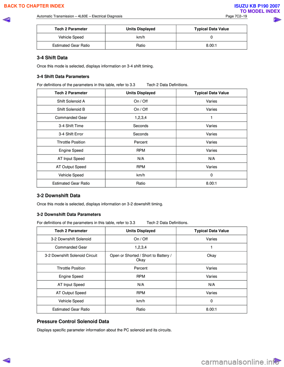
Tech 2 Parameter Units Displayed Typical Data Value
Vehicle Speed km/h 0
Estimated Gear Ratio Ratio 8.00:1
3-4 Shift Data
Once this mode is selected, displays information on 3-4 shift timing.
3-4 Shift Data Parameters
For definitions of the parameters in this table, refer to 3.3 Tech 2 Data Definitions.
Tech 2 Parameter Units Displayed Typical Data Value
Shift Solenoid A On / Off Varies
Shift Solenoid B On / Off Varies
Commanded Gear 1,2,3,4 1
3-4 Shift Time Seconds Varies
3-4 Shift Error Seconds Varies
Throttle Position Percent Varies
Engine Speed RPM Varies
AT Input Speed N/A N/A
AT Output Speed RPM Varies
Vehicle Speed km/h 0
Estimated Gear Ratio Ratio 8.00:1
3-2 Downshift Data
Once this mode is selected, displays information on 3-2 downshift timing.
3-2 Downshift Data Parameters
For definitions of the parameters in this table, refer to 3.3 Tech 2 Data Definitions.
Tech 2 Parameter Units Displayed Typical Data Value
3-2 Downshift Solenoid On / Off Varies
Commanded Gear 1,2,3,4 1
3-2 Downshift Solenoid Circuit Open or Shorted / Short to Battery /
Okay Okay
Throttle Position
Percent Varies
Engine Speed RPM Varies
AT Input Speed N/A N/A
AT Output Speed RPM Varies
Vehicle Speed km/h 0
Estimated Gear Ratio Ratio 8.00:1
Pressure Control Solenoid Data
Displays specific parameter information about the PC solenoid and its circuits.
BACK TO CHAPTER INDEX
TO MODEL INDEX
ISUZU KB P190 2007