ISUZU KB P190 2007 Workshop Repair Manual
Manufacturer: ISUZU, Model Year: 2007, Model line: KB P190, Model: ISUZU KB P190 2007Pages: 6020, PDF Size: 70.23 MB
Page 3741 of 6020
Powertrain Interface Module – V6 Page 6E1–80
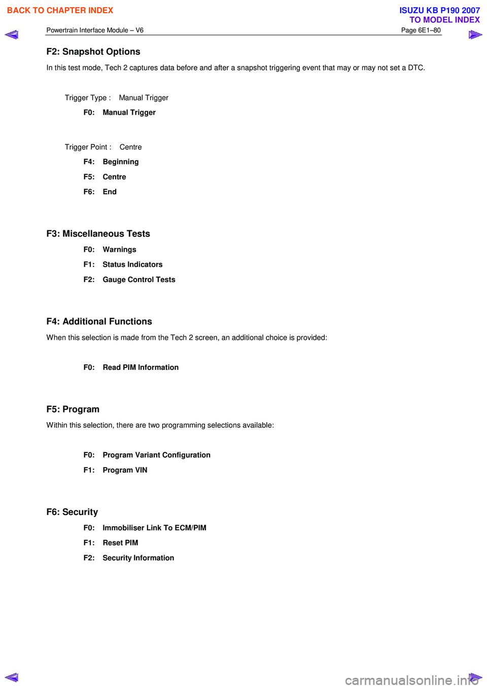
F2: Snapshot Options
In this test mode, Tech 2 captures data before and after a snapshot triggering event that may or may not set a DTC.
Trigger Type : Manual Trigger
F0: Manual Trigger
Trigger Point : Centre
F4: Beginning
F5: Centre
F6: End
F3: Miscellaneous Tests
F0: Warnings
F1: Status Indicators
F2: Gauge Control Tests
F4: Additional Functions
W hen this selection is made from the Tech 2 screen, an additional choice is provided:
F0: Read PIM Information
F5: Program
W ithin this selection, there are two programming selections available:
F0: Program Variant Configuration
F1: Program VIN
F6: Security
F0: Immobiliser Link To ECM/PIM
F1: Reset PIM
F2: Security Information
BACK TO CHAPTER INDEX
TO MODEL INDEX
ISUZU KB P190 2007
Page 3742 of 6020

Powertrain Interface Module – V6 Page 6E1–81
13.3 Powertrain Interface Module Data List
Diagnostic Data Display
Tech 2 Display Units Displayed Switch On Switch Off
AC Switch On/Off On Off
Cruise Cancel Switch Active/Inactive Active Inactive
Cruise Resume Switch Active/Inactive Active Inactive
Cruise Set Switch Active/Inactive Active Inactive
Cruise Main Switch Active/Inactive Active Inactive
Cruise Control Set Lamp On/Off On Off
Cruise Control On Lamp On/Off On Off
Power Drive Switch On/Off On Off
Power Drive Lamp On/Off On Off
3rd Start Switch On/Off On Off
3rd Start Lamp On/Off On Off
4W D Low Gear Active/Inactive Active Inactive
G-Sensor V 2.43 2.43
G-Sensor Pa 0.027 0.027
Engine Speed RPM 152 1093
Coolant temperature Input °C 35 25
Coolant Temperature % 70 70
Fuel Level Input % 26 26
Fuel Level % 43 43
Alternator Lamp On/Off On Off
Oil Pressure Lamp On/Off On Off
SVS Lamp (Service Vehicle soon) On/Off On Off
Check transmission MIL On/Off On Off
Transmission Oil Temperature Lamp On/Off On Off
LED [ - P - ] On/Off On Off
LED [ - R - ] On/Off On Off
LED [ - N - ] On/Off On Off
LED [ - D - ] On/Off On Off
LED [ - 3 - ] On/Off On Off
LED [ - 2 - ] On/Off On Off
LED [ - 1 - ] On/Off On Off
BACK TO CHAPTER INDEX
TO MODEL INDEX
ISUZU KB P190 2007
Page 3743 of 6020
Powertrain Interface Module – V6 Page 6E1–82
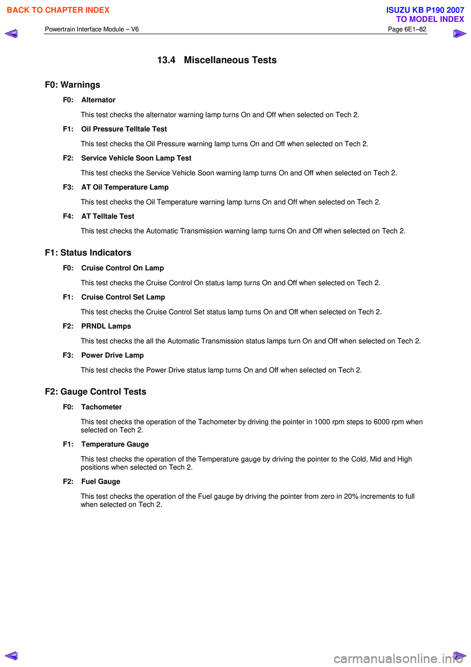
13.4 Miscellaneous Tests
F0: Warnings
F0: Alternator
This test checks the alternator warning lamp turns On and Off when selected on Tech 2.
F1: Oil Pressure Telltale Test
This test checks the Oil Pressure warning lamp turns On and Off when selected on Tech 2.
F2: Service Vehicle Soon Lamp Test
This test checks the Service Vehicle Soon warning lamp turns On and Off when selected on Tech 2.
F3: AT Oil Temperature Lamp
This test checks the Oil Temperature warning lamp turns On and Off when selected on Tech 2.
F4: AT Telltale Test
This test checks the Automatic Transmission warning lamp turns On and Off when selected on Tech 2.
F1: Status Indicators
F0: Cruise Control On Lamp
This test checks the Cruise Control On status lamp turns On and Off when selected on Tech 2.
F1: Cruise Control Set Lamp
This test checks the Cruise Control Set status lamp turns On and Off when selected on Tech 2.
F2: PRNDL Lamps
This test checks the all the Automatic Transmission status lamps turn On and Off when selected on Tech 2.
F3: Power Drive Lamp
This test checks the Power Drive status lamp turns On and Off when selected on Tech 2.
F2: Gauge Control Tests
F0: Tachometer
This test checks the operation of the Tachometer by driving the pointer in 1000 rpm steps to 6000 rpm when
selected on Tech 2.
F1: Temperature Gauge
This test checks the operation of the Temperature gauge by driving the pointer to the Cold, Mid and High
positions when selected on Tech 2.
F2: Fuel Gauge
This test checks the operation of the Fuel gauge by driving the pointer from zero in 20% increments to full when selected on Tech 2.
BACK TO CHAPTER INDEX
TO MODEL INDEX
ISUZU KB P190 2007
Page 3744 of 6020
Powertrain Interface Module – V6 Page 6E1–83
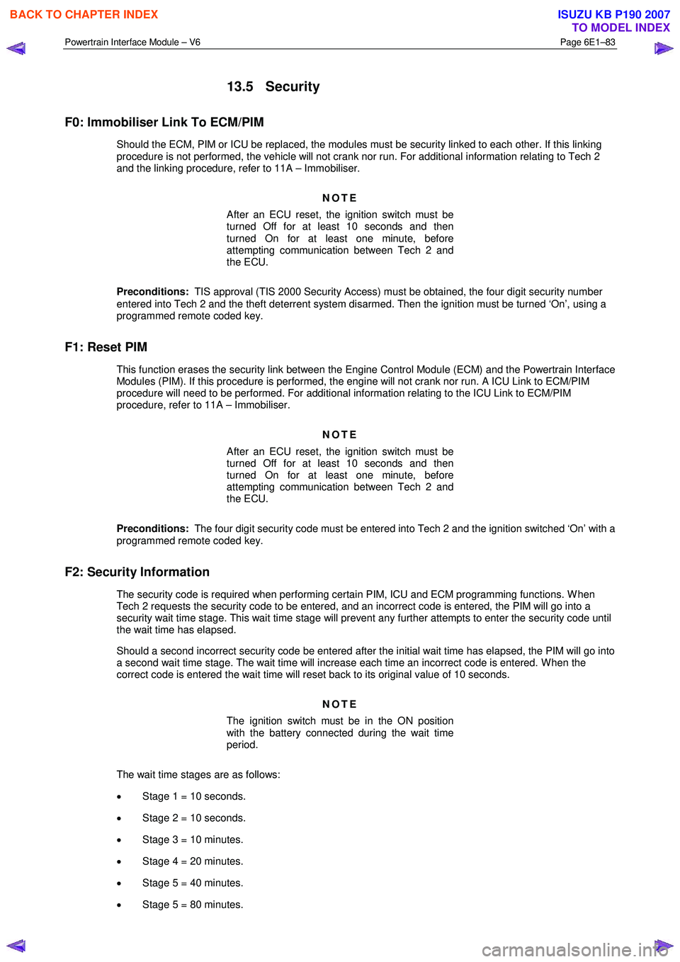
13.5 Security
F0: Immobiliser Link To ECM/PIM
Should the ECM, PIM or ICU be replaced, the modules must be security linked to each other. If this linking
procedure is not performed, the vehicle will not crank nor run. For additional information relating to Tech 2
and the linking procedure, refer to 11A – Immobiliser.
NOTE
After an ECU reset, the ignition switch must be
turned Off for at least 10 seconds and then
turned On for at least one minute, before
attempting communication between Tech 2 and
the ECU.
Preconditions: TIS approval (TIS 2000 Security Access) must be obtained, the four digit security number
entered into Tech 2 and the theft deterrent system disarmed. Then the ignition must be turned ‘On’, using a
programmed remote coded key.
F1: Reset PIM
This function erases the security link between the Engine Control Module (ECM) and the Powertrain Interface Modules (PIM). If this procedure is performed, the engine will not crank nor run. A ICU Link to ECM/PIM
procedure will need to be performed. For additional information relating to the ICU Link to ECM/PIM
procedure, refer to 11A – Immobiliser.
NOTE
After an ECU reset, the ignition switch must be
turned Off for at least 10 seconds and then
turned On for at least one minute, before
attempting communication between Tech 2 and
the ECU.
Preconditions: The four digit security code must be entered into Tech 2 and the ignition switched ‘On’ with a
programmed remote coded key.
F2: Security Information
The security code is required when performing certain PIM, ICU and ECM programming functions. W hen Tech 2 requests the security code to be entered, and an incorrect code is entered, the PIM will go into a
security wait time stage. This wait time stage will prevent any further attempts to enter the security code until
the wait time has elapsed.
Should a second incorrect security code be entered after the initial wait time has elapsed, the PIM will go into a second wait time stage. The wait time will increase each time an incorrect code is entered. W hen the
correct code is entered the wait time will reset back to its original value of 10 seconds.
NOTE
The ignition switch must be in the ON position
with the battery connected during the wait time
period.
The wait time stages are as follows: • Stage 1 = 10 seconds.
• Stage 2 = 10 seconds.
• Stage 3 = 10 minutes.
• Stage 4 = 20 minutes.
• Stage 5 = 40 minutes.
• Stage 5 = 80 minutes.
BACK TO CHAPTER INDEX
TO MODEL INDEX
ISUZU KB P190 2007
Page 3745 of 6020

Powertrain Interface Module – V6 Page 6E1–84
Tech 2 PIM Security Information Data List
The Tech 2 PIM Security Information Data List displays the PIM's current security status.
To view the data list:
1 Connect Tech 2 to the data link connector (DLC) and turn the ignition switch on.
2 On Tech 2 select: Body / Powertrain Interface Module / Security / Security Information .
NOTE
The Tech 2 PIM Security Information Data List
typical display values are obtained from a
correctly operating vehicle under the following
conditions:
• ignition switched on,
• engine not running, and
• vehicle is stationary.
Tech 2 Parameter Units Displayed Typical Display Values
Security Code Programmed Yes / No Yes
Security W ait Time Inactive / Active Inactive
Security W ait Time Inactive / 0:00:00 Inactive
Security Code Reset Counter 0 0
BACK TO CHAPTER INDEX
TO MODEL INDEX
ISUZU KB P190 2007
Page 3746 of 6020

Powertrain Interface Module – V6 Page 6E1–85
14 Specifications
Powertrain Interface Module Bus Cut-off Resistor.................................... 120 Ω
Engine Control Module Bus Cut-off Resistor ............................................ 120 Ω
BACK TO CHAPTER INDEX
TO MODEL INDEX
ISUZU KB P190 2007
Page 3747 of 6020

Powertrain Interface Module – V6 Page 6E1–86
15 Torque Wrench Specifications
Powertrain Interface Module Attaching Screw ............................. 8.0 – 12.0 Nm
Vertical Acceleration Sensor attaching nut ............................... 12.0 – 16.0 Nm
BACK TO CHAPTER INDEX
TO MODEL INDEX
ISUZU KB P190 2007
Page 3748 of 6020
Powertrain Interface Module – V6 Page 6E1–87
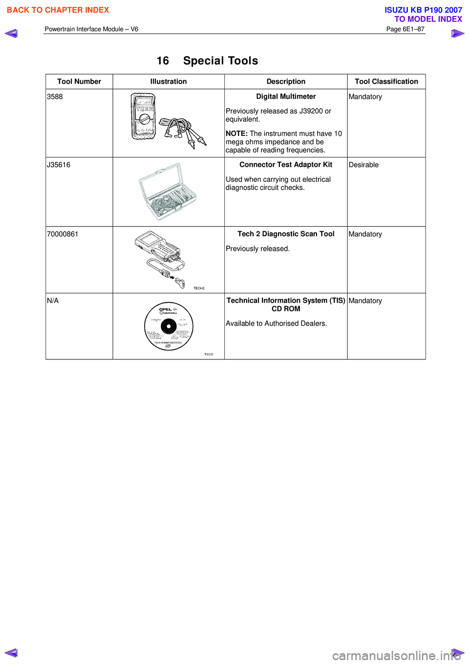
16 Special Tools
Tool Number Illustration Description Tool Classification
3588
Digital Multimeter
Previously released as J39200 or
equivalent.
NOTE: The instrument must have 10
mega ohms impedance and be
capable of reading frequencies. Mandatory
J35616
Connector Test Adaptor Kit
Used when carrying out electrical
diagnostic circuit checks.
Desirable
70000861
Tech 2 Diagnostic Scan Tool
Previously released. Mandatory
N/A
Technical Information System (TIS)
CD ROM
Available to Authorised Dealers. Mandatory
BACK TO CHAPTER INDEX
TO MODEL INDEX
ISUZU KB P190 2007
Page 3749 of 6020
Exhaust System – V6 Page 6F – 1
6F
Exhaust System – V6
ATTENTION
Before performing any service operations or other procedure described in this Section, refer to
1.3 WARNING, CAUTION and NOTES for correct workshop practices with regard to safety and / or
property damage.
1 General Information ............................................................................................................ ...................2
1.1 Emission Reductions ............................................................................................................................................ 2
Euro 3 Emissions Standards ................................................................................................................................ 3
1.2 General Description ............................................................................................................ ................................... 4
Service Notes ......................................................................................................................................................... 5
1.3 WARNING, CAUTION and NOTES..................................................................................................... .................... 5
1.1 Definition of WARNING, CAUTION and NOTE Statements......................................................................... .. 5
W ARNING defined ............................................................................................................................................. 5
CAUTION defined .............................................................................................................................................. 5
NOTE defined .................................................................................................................................................... 6
2 Front and Centre Exhaust Pipe .................................................................................................. ...........7
Removal .................................................................................................................................................................. 7
Reinstallation ......................................................................................................................................................... 8
3 Silencer and Rear Exhaust Pipe............................................................................................................9
Removal .................................................................................................................................................................. 9
Reinstallation ......................................................................................................................................................... 9
4 Torque Wrench Specifications............................................................................................................10
BACK TO CHAPTER INDEX
TO MODEL INDEX
ISUZU KB P190 2007
Page 3750 of 6020
Exhaust System – V6 Page 6F – 2
1 General Information
Information contained within this section describes the general exhaust system.
1.1 Emission Reductions
Through developments in various vehicle emissions reduction systems, significant reductions in emissions have been
achieved. The developments have been primarily concerned with refinements in engine calibration and the optimisation
of exhaust system catalytic converter configurations.
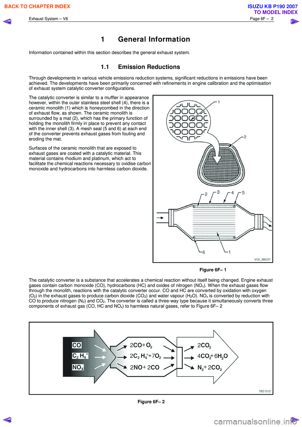
The catalytic converter is similar to a muffler in appearance
however, within the outer stainless steel shell (4), there is a
ceramic monolith (1) which is honeycombed in the direction
of exhaust flow, as shown. The ceramic monolith is
surrounded by a mat (2), which has the primary function of
holding the monolith firmly in place to prevent any contact
with the inner shell (3). A mesh seal (5 and 6) at each end
of the converter prevents exhaust gases from fouling and
eroding the mat.
Surfaces of the ceramic monolith that are exposed to
exhaust gases are coated with a catalytic material. This
material contains rhodium and platinum, which act to
facilitate the chemical reactions necessary to oxidise carbon
monoxide and hydrocarbons into harmless carbon dioxide.
Figure 6F– 1
The catalytic converter is a substance that accelerates a chemical reaction without itself being changed. Engine exhaust
gases contain carbon monoxide (CO), hydrocarbons (HC) and oxides of nitrogen (NO
x). W hen the exhaust gases flow
through the monolith, reactions with the catalytic converter occur. CO and HC are converted by oxidation with oxygen
(O
2) in the exhaust gases to produce carbon dioxide (CO2) and water vapour (H2O). NOx is converted by reduction with
CO to produce nitrogen (N
2) and CO2. The converter is called a three-way type because it simultaneously converts three
components of exhaust gas (CO, HC and NO
x) to harmless natural gases, refer to Figure 6F– 2
Figure 6F– 2
BACK TO CHAPTER INDEX
TO MODEL INDEX
ISUZU KB P190 2007