stop start ISUZU KB P190 2007 Workshop Service Manual
[x] Cancel search | Manufacturer: ISUZU, Model Year: 2007, Model line: KB P190, Model: ISUZU KB P190 2007Pages: 6020, PDF Size: 70.23 MB
Page 2009 of 6020
ENGINE DIAGNOSIS (C24SE) 6-9
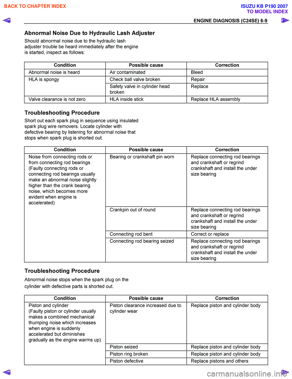
Abnormal Noise Due to Hydraulic Lash Adjuster
Should abnormal noise due to the hydraulic lash
adjuster trouble be heard immediately after the engine
is started, inspect as follows:
Condition Possible cause Correction
Abnormal noise is heard Air contaminated Bleed
HLA is spongy Check ball valve broken Repair
Safety valve in cylinder head
broken Replace
Valve clearance is not zero HLA inside stick
Replace HLA assembly
Troubleshooting Procedure
Short out each spark plug in sequence using insulated
spark plug wire removers. Locate cylinder with
defective bearing by listening for abnormal noise that
stops when spark plug is shorted out.
Condition Possible cause Correction
Noise from connecting rods or
from connecting rod bearings
(Faulty connecting rods or
connecting rod bearings usually
make an abnormal noise slightly
higher than the crank bearing
noise, which becomes more
evident when engine is
accelerated) Bearing or crankshaft pin worn Replace connecting rod bearings
and crankshaft or regrind
crankshaft and install the under
size bearing
Crankpin out of round Replace connecting rod bearings
and crankshaft or regrind
crankshaft and install the under
size bearing
Connecting rod bent Correct or replace
Connecting rod bearing seized Replace connecting rod bearings
and crankshaft or regrind
crankshaft and install the under
size bearing
Troubleshooting Procedure
Abnormal noise stops when the spark plug on the
cylinder with defective parts is shorted out.
Condition Possible cause Correction
Piston and cylinder
(Faulty piston or cylinder usually
makes a combined mechanical
thumping noise which increases
when engine is suddenly
accelerated but diminishes
gradually as the engine warms up) Piston clearance increased due to
cylinder wear Replace piston and cylinder body
Piston seized Replace piston and cylinder body
Piston ring broken Replace piston and cylinder body
Piston defective Replace pistons and others
BACK TO CHAPTER INDEX
TO MODEL INDEX
ISUZU KB P190 2007
Page 2013 of 6020
ENGINE DIAGNOSIS (C24SE) 6-13
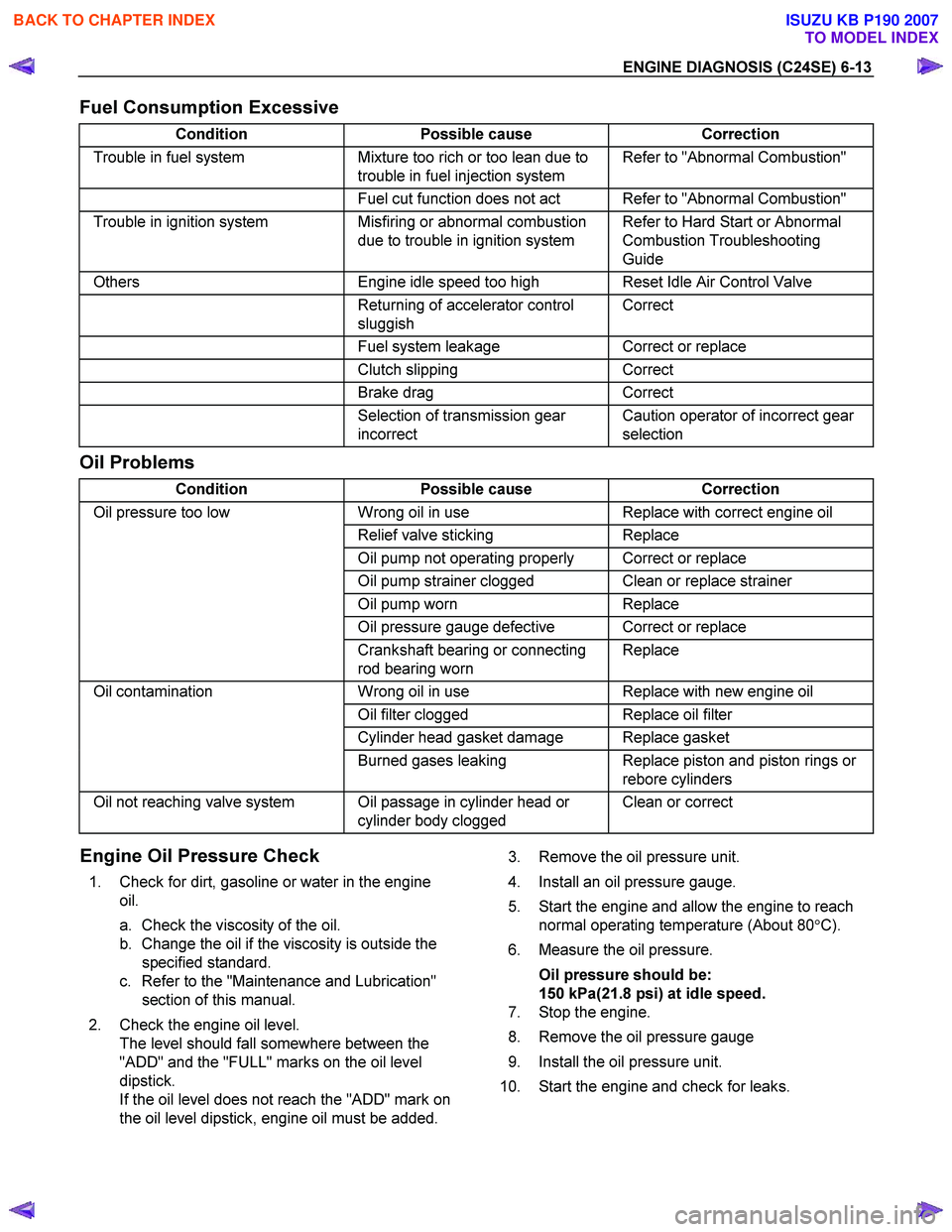
Fuel Consumption Excessive
Condition Possible cause Correction
Trouble in fuel system Mixture too rich or too lean due to
trouble in fuel injection system Refer to "Abnormal Combustion"
Fuel cut function does not act Refer to "Abnormal Combustion"
Trouble in ignition system Misfiring or abnormal combustion
due to trouble in ignition system Refer to Hard Start or Abnormal
Combustion Troubleshooting
Guide
Others Engine idle speed too high Reset Idle Air Control Valve
Returning of accelerator control
sluggish Correct
Fuel system leakage Correct or replace
Clutch slipping Correct
Brake drag Correct
Selection of transmission gear
incorrect Caution operator of incorrect gear
selection
Oil Problems
Condition Possible cause Correction
Oil pressure too low Wrong oil in use Replace with correct engine oil
Relief valve sticking Replace
Oil pump not operating properly Correct or replace
Oil pump strainer clogged Clean or replace strainer
Oil pump worn Replace
Oil pressure gauge defective Correct or replace
Crankshaft bearing or connecting
rod bearing worn Replace
Oil contamination
Wrong oil in use Replace with new engine oil
Oil filter clogged Replace oil filter
Cylinder head gasket damage Replace gasket
Burned gases leaking Replace piston and piston rings or
rebore cylinders
Oil not reaching valve system Oil passage in cylinder head or cylinder body clogged Clean or correct
Engine Oil Pressure Check
1. Check for dirt, gasoline or water in the engine
oil.
a. Check the viscosity of the oil.
b. Change the oil if the viscosity is outside the specified standard.
c. Refer to the "Maintenance and Lubrication" section of this manual.
2. Check the engine oil level. The level should fall somewhere between the
"ADD" and the "FULL" marks on the oil level
dipstick.
If the oil level does not reach the "ADD" mark on
the oil level dipstick, engine oil must be added.
3. Remove the oil pressure unit.
4. Install an oil pressure gauge.
5. Start the engine and allow the engine to reach normal operating temperature (About 80 °C).
6. Measure the oil pressure.
Oil pressure should be:
150 kPa(21.8 psi) at idle speed.
7. Stop the engine.
8. Remove the oil pressure gauge
9. Install the oil pressure unit.
10. Start the engine and check for leaks.
BACK TO CHAPTER INDEX
TO MODEL INDEX
ISUZU KB P190 2007
Page 2110 of 6020

6B-6 ENGINE COOLING
Draining and Refilling Cooling
System
Before draining the cooling system, inspect the system and
perform any necessary service to ensure that it is clean, does
not leak and is in proper working order. The engine coolant
level should be between the "MIN" and "MAX" lines of reserve
tank when the engine is cold. If low, check for leakage and add
engine coolant up to the "MAX" line. There should not be any
excessive deposit of rust or scales around the radiator cap or
radiator filler hole, and the engine coolant should also be free
from oil.
Replace the engine coolant if excessively dirty.
1. Completely drain the cooling system by opening the drain
plug at the bottom of the radiator.
2. Remove the radiator cap.
WARNING: TO AVOID THE DANGER OF BEING BURNED,
DO NOT REMOVE THE CAP WHILE THE ENGINE AND
RADIATOR ARE STILL HOT. SCALDING FLUID AND
STEAM CAN BE BLOWN OUT UNDER PRESSURE.
3. Disconnect all hoses from the engine coolant reserve tank.
Scrub and clean the inside of the reserve tank with soap and water. Flush it well with clean water, then drain it. Install
the reserve tank and hoses.
4. Refill the cooling system with the engine coolant using a solution that is at least 50 percent antifreeze.
5. Fill the radiator to the base of the filler neck.
Fill the engine coolant reserve tank to "MAX" line when the engine is cold.
6. Block the drive wheels and firmly apply the parking brake and place the shift lever in the "NEUTRAL" position.
7. Remove the radiator cap. Start the engine and warm it up at 2,500 - 3,000 rpm for about 30 minutes.
8. W hen the air comes out from the radiator filler neck and the engine coolant level has gone down, replenish with the
engine coolant. Repeat this procedure until the engine
coolant level does not go down. Then stop the engine and
install the radiator cap. Let the engine cool down.
9. After the engine has cooled, replenish with engine coolant up to the "MAX" line of the reserve tank.
10. Start the engine. W ith the engine running at 3,000 rpm, make sure there is no running water sound from the heate
r
core (behind the center console).
11. If the running water sound is heard, repeat steps 8 to 10.
BACK TO CHAPTER INDEX
TO MODEL INDEX
ISUZU KB P190 2007
Page 2113 of 6020

ENGINE COOLING 6B-9
Thermostat
Removal
1. Disconnect battery ground cable.
2. Drain engine coolant from the radiator and engine.
3. Disconnect radiator hose from the inlet pipe.
4. Remove thermostat housing.
5. Remove thermostat from thermostat housing.
Inspection
Suspend the thermostat in a water-filled container using thin
wire. Place a thermometer next to the thermostat.
Do not directly heat the thermostat.
Gradually increase the water temperature. Stir the water so
that the entire water is same temperature.
Confirm the temperature when the valve first begins to open.
Valve opening temperature 92 °
°°
°
C (197.6 °
°°
°
F)
Confirm the temperature when the valve is fully opened.
Valve full open temperature 107 °
°°
°
C(224.6 °
°°
°
F)
Make necessary repair and parts replacement if extreme wear
or damage is found during inspection.
Installation
1. Before installing thermostat, coat sealing surface with
silicon grease.
2. Install O-ring.
3. Install thermostat housing and tighten bolts to the specified torque.
Torque: 15 N ⋅
⋅⋅
⋅
m (1.5 kgf ⋅
⋅⋅
⋅
m)
4. Installation rubber hose.
5. Replenish engine coolant (EC).
6. Start engine and check for EC leakage.
Fan Clutch with Cooling Fan
Inspection and Repair
Make necessary correction or parts replacement if wear,
damage or any other abnormal condition are found through
inspection.
Visually inspect for damage, leak (silicon grease) or other
abnormal conditions.
1. Inspection (on-vehicle)
1) Turn the fan clutch by hand when in a low temperature condition before starting the engine, and confirm that it
can be turned readily.
2) Start the engine to warm it up until the temperature at the fan clutch portion gets to around 80 °C. Then stop the
engine and confirm that the fan clutch can be turned with
considerable effort (clutch torque) when turned by hand.
BACK TO CHAPTER INDEX
TO MODEL INDEX
ISUZU KB P190 2007
Page 2117 of 6020

ENGINE COOLING 6B-13
Installation
1. Install radiator assembly, taking care not to damage theradiator core.
2. Install the radiator assembly.
3. Connect reserve tank hose.
4. Connect radiator inlet hose and outlet hose.
5. Pour engine coolant up to filler neck of radiator, and up to MAX mark of reserve tank.
Important operation (in case of 100% engine coolant change) procedure for filling with engine coolant.
• Remove radiator cap.
• Fill with engine coolant to the radiator filler neck.
• Fill with EC to the "MAX" line on the reservoir tank.
• Start the engine with the radiator cap removed and bring to
operating temperature by running engine at 2,500 - 3,000
rpm for 30 minutes.
• By engine coolant temperature gauge reading make sure
that the thermostat is open.
• If air bubbles come up to the radiator filler neck, replenish
with engine coolant. Repeat until the EC level does not drop
any further. Install the radiator cap and stop the engine.
• Replenish engine coolant to the "MAX" line on the reservoi
r
tank and leave as it is until the engine gets cool.
•
After the engine gets cool, start the engine and make sure
there is no water running noise heard from the heater core
while the engine runs at 3000 rpm.
• Should water running noise be heard, repeat the same
procedure from the beginning.
Main Data and Specifications
General Specifications
Cooling system Engine Coolant forced circulation
Radiator Tube type corrugated (2 tube in row)
Heat radiation capacity 66.3 kcal/h
Heat radiation area 7.08 m2
Radiator front area 028 m2
Radiator dry (weight) 3.1 kg
Radiator cap valve opening pressure 93.3 – 122.7 kpa
Engine coolant capacity 3.4L
Engine coolant pump Centrifugal type
Thermostat Bypass type
Engine coolant total capacity 8lit
BACK TO CHAPTER INDEX
TO MODEL INDEX
ISUZU KB P190 2007
Page 2124 of 6020
6C-6 ENGINE FUEL (C24SE)
Fuel Filter
Inspection
1. Replace the fuel filter if the fuel leaks from fuel filter
body or if the fuel filter body itself is damaged.
2. Replace the filter if it is clogged with dirt o
r
sediment.
Installation
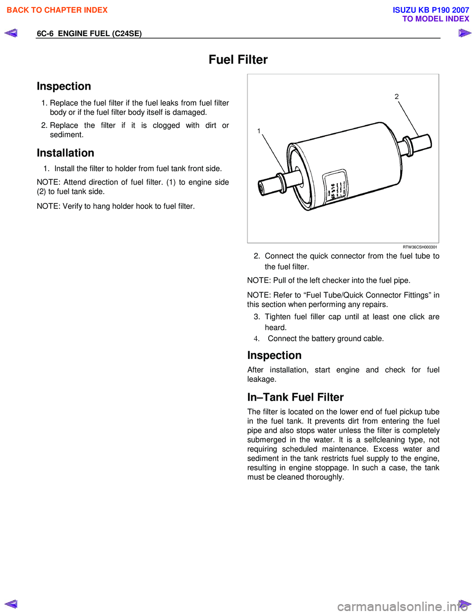
1. Install the filter to holder from fuel tank front side.
NOTE: Attend direction of fuel filter. (1) to engine side
(2) to fuel tank side.
NOTE: Verify to hang holder hook to fuel filter.
RTW 36CSH000301
2. Connect the quick connector from the fuel tube to
the fuel filter.
NOTE: Pull of the left checker into the fuel pipe.
NOTE: Refer to “Fuel Tube/Quick Connector Fittings” in
this section when performing any repairs.
3. Tighten fuel filler cap until at least one click are heard.
4. Connect the battery ground cable.
Inspection
After installation, start engine and check for fuel
leakage.
In–Tank Fuel Filter
The filter is located on the lower end of fuel pickup tube
in the fuel tank. It prevents dirt from entering the fuel
pipe and also stops water unless the filter is completel
y
submerged in the water. It is a selfcleaning type, not
requiring scheduled maintenance. Excess water and
sediment in the tank restricts fuel supply to the engine,
resulting in engine stoppage. In such a case, the tank
must be cleaned thoroughly.
BACK TO CHAPTER INDEX
TO MODEL INDEX
ISUZU KB P190 2007
Page 2132 of 6020

6C-14 ENGINE FUEL (C24SE)
Removal
CAUTION: When repair to the fuel system has been
completed, start engine and check the fuel system
for loose connection or leakage. For the fuel system
diagnosis, see Section “Driveability and Emission".
1. Disconnect battery ground cable.
2. Loosen slowly the fuel filler cap.
NOTE: To prevent spouting out fuel to change the
pressure in the fuel tank.
NOTE: Cover opening of the filler neck to prevent an
y
dust entering.
3. Jack up the vehicle.
4. Support underneath of the fuel tank with a lifter.
5. Remove the inner liner of the wheel house on rea
r
left side.
6. Remove fasten bolt to the filler neck from the body.
7. Disconnect the quick connector (8) into the fuel
tube from the fuel pipe and the evapo tube from
evapo joint connector.
NOTE: Cover the quick connector to prevent any dust
entering and fuel leaking.
NOTE: Refer to “Fuel Tube/Quick Connector Fittings” in
this section when performing any repairs.
8. Remove fasten bolt (1) to the tank band and the tank band (2).
9. Disconnect the pump and sender connector on the
fuel pump and remove the harness from weld clip
on the fuel tank.
10. Lower the fuel tank (6).
NOTE: W hen the fuel tank is lowered from the vehicle,
don’t scratch each hose and tube by around other pars.
Installation
1. Rise the fuel tank into position.
NOTE: Ensure hoses and tubes do not foul on othe
r
component. 2. Connect the pump and sender connector to the
fuel pump and install harness to into the plastic clip
welded to the top of the fuel tank..
NOTE: The connector must be certainly connected
against stopper.
Ensure tank band anchor mates with guide hole on
frame.
3. Install the tank band to fasten bolt.
Torque: 68 N ⋅
⋅⋅
⋅
m (6.9kg ⋅
⋅⋅
⋅
m/50 lb ft)
NOTE: The anchor of the tank band must be certainl
y
installed to guide hole on frame. 4. Connect the quick connector from the fuel tube to
the fuel pipe and the evapo tube from evapo joint
connector.
NOTE: Pull off the left checker into the fuel pipe.
NOTE: Refer to “Fuel Tube/Quick Connector Fittings” in
this section when performing any repairs.
5. Install the filler neck to the body by bolt.
6. Install the inner liner of the wheel house on rea
r
side.
7. Remove lifter to support underneath of the fuel tank.
8. Put back the vehicle.
9. Tigten the filler cap until at least three clicks are
heard.
10. Connect the battery ground cable.
BACK TO CHAPTER INDEX
TO MODEL INDEX
ISUZU KB P190 2007
Page 2150 of 6020

6D3-2 STARTING AND CHARGING SYSTEM
Starting System
General Description
Cranking Circuit
The cranking system consists of a battery, starter, starter
switch, starter relay, etc. These main components are
connected.
Starter
The cranking system employs a magnetic type reduction
starter in which the motor shaft is also used as a pinion shaft.
W hen the starter switch is turned on, the contacts of magnetic
switch are closed, and the armature rotates. At the same time,
the plunger is attracted, and the pinion is pushed forward by
the shift lever to mesh with the ring gear.
Then, the ring gear runs to start the engine. W hen the engine
starts and the starter switch is turned off, the plunger returns,
the pinion is disengaged from the ring gear, and the armature
stops rotation. W hen the engine speed is higher than the
pinion, the pinion idles, so that the armature is not driven.
Service Precaution
CAUTION:
Always use the correct fastener in the proper location.
When you replace a fastener, use ONLY the exact part
number for that application. ISUZU will call out those
fasteners that require a replacement after removal. ISUZU
will also call out the fasteners that require thread lockers
or thread sealant. UNLESS OTHERWISE SPECIFIED, do
not use supplemental coatings (Paints, greases, or other
corrosion inhibitors) on threaded fasteners or fastener
joint interfaces. Generally, such coatings adversely affect
the fastener torque and the joint clamping force, and may
damage the fastener. When you install fasteners, use the
correct tightening sequence and specifications. Following
these instructions can help you avoid damage to parts
and systems.
Diagnosis
Condition Possible cause Correction
Starter does not run Charging failure Repair charging system
Battery Failure Replace Battery
Terminal connection failure Repair or replace terminal connector
and/or wiring harness
Starter switch failure Repair or replace starter switch
Starter failure Repair or replace starter
BACK TO CHAPTER INDEX
TO MODEL INDEX
ISUZU KB P190 2007
Page 2156 of 6020
6D3-8 STARTING AND CHARGING SYSTEM
General On-Vehicle Inspection
The operating condition of charging system is indicated by the
charge warning lamp. The warning lamp comes on when the
starter switch is turned to "ON" position. The charging system
operates normally if the lamp goes off when the engine starts.
If the warning lamp shows abnormality or if undercharged or
overcharged battery condition is suspected, perform diagnosis
by checking the charging system as follows:
1. Check visually the belt and wiring connector.
2. W ith the engine stopped, turn the stator switch to "ON" position and observe the warning lamp.
If lamp does not come on:
Disconnect wiring connector from generator, and ground the terminal "L" on connector side.
If lamp comes on:
Repair or replace the generator.
Generator
Removal
1. Disconnect battery ground cable.
2. Move drive belt tensioner to loose side using wrench then remove drive belt.
3. Disconnect terminal "B" wiring connector and connector.
4. Remove generator assembly.
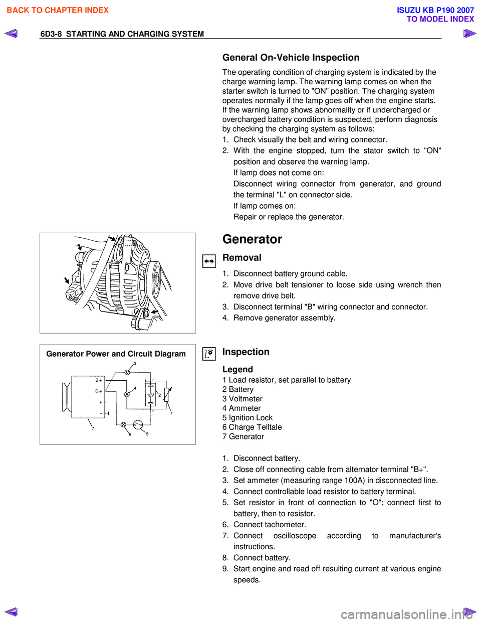
Generator Power and Circuit Diagram
Inspection
Legend
1 Load resistor, set parallel to battery
2 Battery
3 Voltmeter
4 Ammeter
5 Ignition Lock
6 Charge Telltale
7 Generator
1. Disconnect battery.
2. Close off connecting cable from alternator terminal "B+".
3. Set ammeter (measuring range 100A) in disconnected line.
4. Connect controllable load resistor to battery terminal.
5. Set resistor in front of connection to "O"; connect first to battery, then to resistor.
6. Connect tachometer.
7. Connect oscilloscope according to manufacturer's instructions.
8. Connect battery.
9. Start engine and read off resulting current at various engine speeds.
BACK TO CHAPTER INDEX
TO MODEL INDEX
ISUZU KB P190 2007
Page 2161 of 6020
STARTING AND CHARGING SYSTEM 6D3-13
5. During current output tests please make sure that the
ammeter is securely connceted into the charge circuit.
6. Some battery powered timing lights can produce high transient voltages when connected or disconnected. Onl
y
disconnect or connect timing lights when the engine is
switched off.
7. Make sure the warning lamp circuit is functioning normall
y
before commencing tests.
8. Battery isolation switches must only be operated when the engine is stopped.
9. To protect the charging system when using 240 volt chargers it is recommeneded that the battery is
disconnected whilst charging.
10. Due to the very low resistance value of the stator winding it may not be possible to obtain accurate readings without
special equipment.
11. 12 volts must never be connected to the "L" terminal of the regulator as this will damage the lamp driver circuit.
12. No loads apart from the warning lamp can be connected to the "L" termainal. The "W " terminal is provided for this
purpose.
Disassembly
1. Mark the relative positions of the end housings in relation to the stator assembly to aid reassembly. Use a permanent
marking pen do not use centre punched as this can cause
misalignmnet of the housings.
2. Remove the EP regulator from the slipring end housing b
y
removing the two screws. Tilt the regulator slightly from the
plug connection until the regulator clears the housing, then
lift clear.
3. Remove the four through bolts.
4. Carefully remove the stator assembly along with the slipring end housing taking care not to put strain on the stator wires.
5. To disconnect the stator from the rectifier assembly, grasp the stator wires close to the wire loop with a pair of long
nosed pliers, heat the joint with a soldering iron, when the
point becomes plastic apply a slight twisting motion to the
wires, then pull upwards to release the wires. Remove the
stator.
This procedure opens the wire loop to release the stato
r
connections easily.
6. To remove the rectifier remove the three retaining scre
w
and the B+ terminal nut and washers.
Note: the B+ bolt and the positive heatsink retaining screw are
fitted with mica insulating washers.
These must be discarded and replaced with new washers and
heatsink compound.
BACK TO CHAPTER INDEX
TO MODEL INDEX
ISUZU KB P190 2007