sensor ISUZU KB P190 2007 Workshop Repair Manual
[x] Cancel search | Manufacturer: ISUZU, Model Year: 2007, Model line: KB P190, Model: ISUZU KB P190 2007Pages: 6020, PDF Size: 70.23 MB
Page 2216 of 6020
6E–46 ENGINE DRIVEABILITY AND EMISSIONS
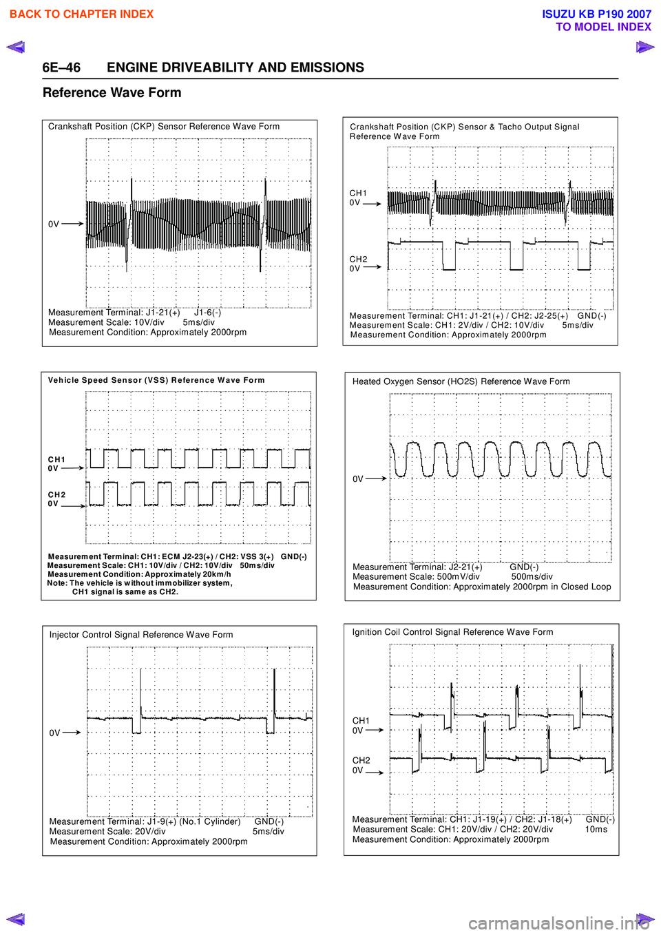
Reference Wave Form
Crankshaft Position (CKP) Sensor Reference W ave Form
0V
Measurem ent Term inal: J1-21(+) J1-6(-)
Measurem ent Scale: 10V/div 5m s/div
Measurem ent Condition: Approxim ately 2000rpm
Vehicle Speed Sensor (VSS) Reference Wave Form
CH1
0V
CH2
0V
M easurem ent Term inal: CH1: ECM J2-23(+) / CH2: VSS 3(+) GND(-)
M easurem ent Scale: CH1: 10V/div / CH2: 10V/div 50m s/div
Measurem ent Condition: Approxim ately 20km /h
Note: The vehicle is w ithout imm obilizer system,
CH1 signal is same as CH2.
Injector Control Signal Reference W ave Form
0V
Measurem ent Term inal: J1-9(+) (No.1 Cylinder) GND(-)
Measurement Scale: 20V/div 5ms/div
Measurem ent Condition: Approximately 2000rpm
Crankshaft Position (CKP) Sensor & Tacho Output Signal
Reference W ave Form
CH1
0V
CH2
0V
Measurement Terminal: CH1: J1-21(+) / CH2: J2-25(+) GND(-)
Measurement Scale: CH1: 2V/div / CH2: 10V/div 5ms/div
Measurement Condition: Approximately 2000rpm
Heated Oxygen Sensor (HO2S) Reference Wave Form
0V
Measurem ent Terminal: J2-21(+) GND(-)
Measurem ent Scale: 500m V/div 500m s/div
Measurement Condition: Approxim ately 2000rpm in Closed Loop
Ignition Coil Control Signal Reference Wave Form
CH1
0V
CH2
0V
Measurement Terminal: CH1: J1-19(+) / CH2: J1-18(+) GND(-)
Measurem ent Scale: CH1: 20V/div / CH2: 20V/div 10m s
Measurement Condition: Approximately 2000rpm
BACK TO CHAPTER INDEX
TO MODEL INDEX
ISUZU KB P190 2007
Page 2218 of 6020
6E–48 ENGINE DRIVEABILITY AND EMISSIONS
GENERAL DESCRIPTION FOR ECM AND
SENSORS
Engine Control Module (ECM)
The engine control module (ECM) is located on the
intake manifold. The ECM controls the following.
• Fuel metering system
• Ignition timing
• On-board diagnostics for electrical functions.
The ECM constantly observes the information from vari-
ous sensors. The ECM controls the systems that affect
vehicle performance. And it performs the diagnostic
function of the system.
The function can recognize operational problems, and
warn to the driver through the check engine lamp, and
store diagnostic trouble code (DTC). DTCs identify the
problem areas to aid the technician in marking repairs.
The input / output devices in the ECM include analog to
digital converts, signal buffers, counters and drivers.
The ECM controls most components with electronic
switches which complete a ground circuit when turned
on.
Inputs (Operating condition read):
• Battery voltage
• Electrical ignition
• Exhaust oxygen content
• Intake manifold pressure
• Intake air temperature
• Engine coolant temperature
• Crankshaft position • Knock signal
• Throttle position
• Vehicle speed
• Power steering pressure
• Air conditioning request on or off
Outputs (Systems controlled):
• Ignition control
• Fuel control
• Idle air control
• Fuel pump
• EVAP canister purge
• Air conditioning
• Diagnostics functions
Manifold Absolute Pressure (MAP) Sensor
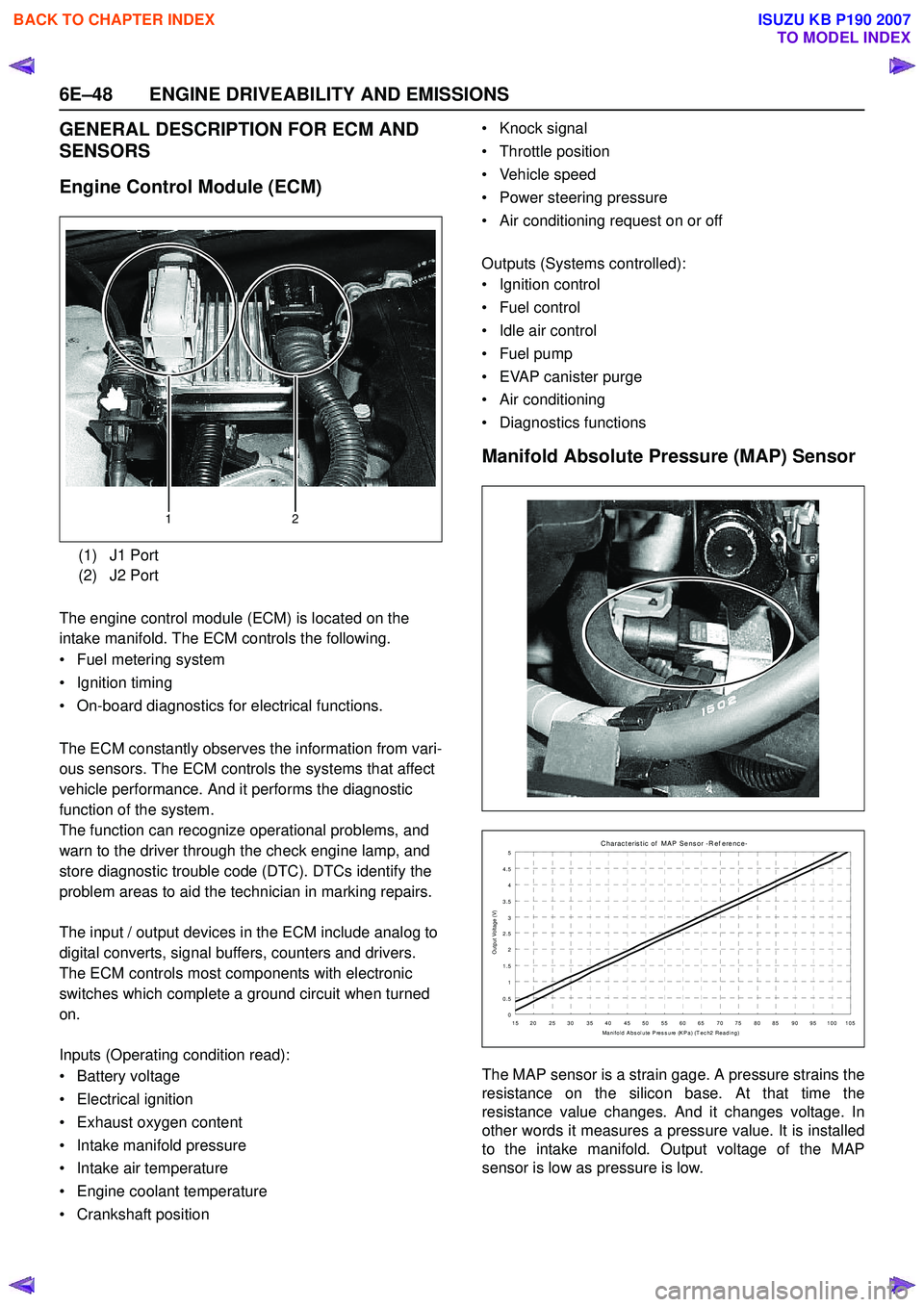
The MAP sensor is a strain gage. A pressure strains the
resistance on the silicon base. At that time the
resistance value changes. And it changes voltage. In
other words it measures a pressure value. It is installed
to the intake manifold. Output voltage of the MAP
sensor is low as pressure is low.
(1) J1 Port
(2) J2 Port
12
C harac t eris t ic of MAP Sens or -R ef erenc e-
0
0.5 1
1.5 2
2.5
3
3.5 4
4.5 5
15 20 25 30 35 40 45 50 55 60 65 70 75 80 85 90 95 100 105 Manifold Abs olute Press ure (KPa) (T ec h2 Reading)
Output Voltage (V)
BACK TO CHAPTER INDEX
TO MODEL INDEX
ISUZU KB P190 2007
Page 2219 of 6020
ENGINE DRIVEABILITY AND EMISSIONS 6E–49
Throttle Position Sensor (TPS)
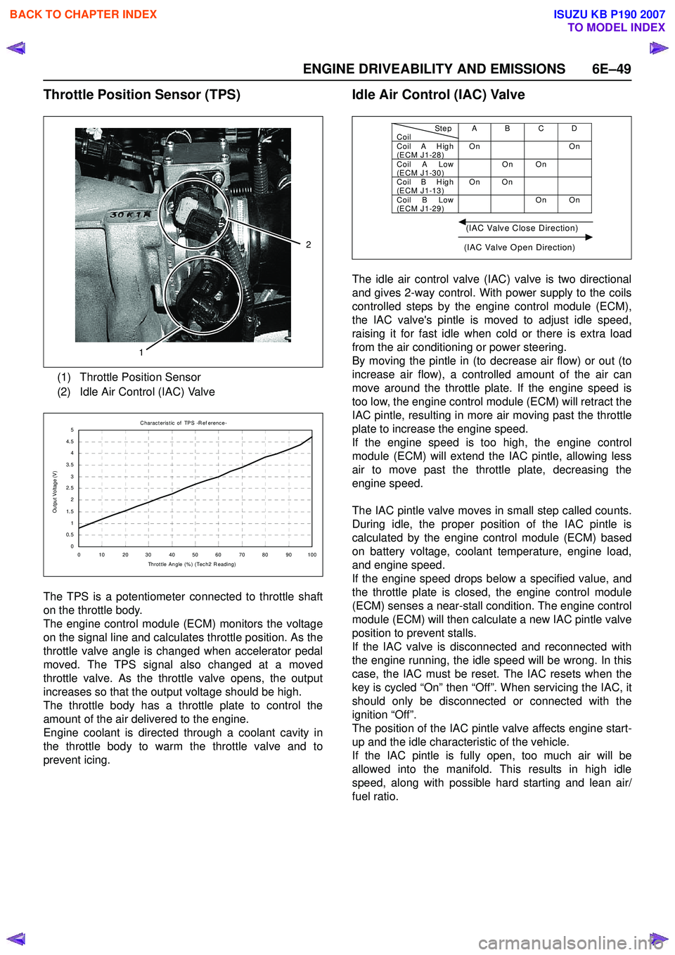
The TPS is a potentiometer connected to throttle shaft
on the throttle body.
The engine control module (ECM) monitors the voltage
on the signal line and calculates throttle position. As the
throttle valve angle is changed when accelerator pedal
moved. The TPS signal also changed at a moved
throttle valve. As the throttle valve opens, the output
increases so that the output voltage should be high.
The throttle body has a throttle plate to control the
amount of the air delivered to the engine.
Engine coolant is directed through a coolant cavity in
the throttle body to warm the throttle valve and to
prevent icing.
Idle Air Control (IAC) Valve
The idle air control valve (IAC) valve is two directional
and gives 2-way control. With power supply to the coils
controlled steps by the engine control module (ECM),
the IAC valve's pintle is moved to adjust idle speed,
raising it for fast idle when cold or there is extra load
from the air conditioning or power steering.
By moving the pintle in (to decrease air flow) or out (to
increase air flow), a controlled amount of the air can
move around the throttle plate. If the engine speed is
too low, the engine control module (ECM) will retract the
IAC pintle, resulting in more air moving past the throttle
plate to increase the engine speed.
If the engine speed is too high, the engine control
module (ECM) will extend the IAC pintle, allowing less
air to move past the throttle plate, decreasing the
engine speed.
The IAC pintle valve moves in small step called counts.
During idle, the proper position of the IAC pintle is
calculated by the engine control module (ECM) based
on battery voltage, coolant temperature, engine load,
and engine speed.
If the engine speed drops below a specified value, and
the throttle plate is closed, the engine control module
(ECM) senses a near-stall condition. The engine control
module (ECM) will then calculate a new IAC pintle valve
position to prevent stalls.
If the IAC valve is disconnected and reconnected with
the engine running, the idle speed will be wrong. In this
case, the IAC must be reset. The IAC resets when the
key is cycled “On” then “Off”. When servicing the IAC, it
should only be disconnected or connected with the
ignition “Off”.
The position of the IAC pintle valve affects engine start-
up and the idle characteristic of the vehicle.
If the IAC pintle is fully open, too much air will be
allowed into the manifold. This results in high idle
speed, along with possible hard starting and lean air/
fuel ratio.
(1) Throttle Position Sensor
(2) Idle Air Control (IAC) Valve
1
2
C harac teris t ic of TPS -R ef erenc e-
0
0.5
1
1.5 2
2.5
3
3.5 4
4.5 5
0 10 2030 405060 7080 90100 Throt t le Angle (% ) (Tec h2 R eading)
Output Voltage (V)
StepCoilAB CDCoil A H igh
(ECM J1-28) On On
Coil A Low
(ECM J1-30) On On
Coil B H igh
(ECM J1-13) On On
Coil B Low
(ECM J1-29) On On
(IAC Valve Close Direction)
(IAC Valve Open Direction)
BACK TO CHAPTER INDEX
TO MODEL INDEX
ISUZU KB P190 2007
Page 2220 of 6020
6E–50 ENGINE DRIVEABILITY AND EMISSIONS
Crankshaft Position (CKP) Sensor
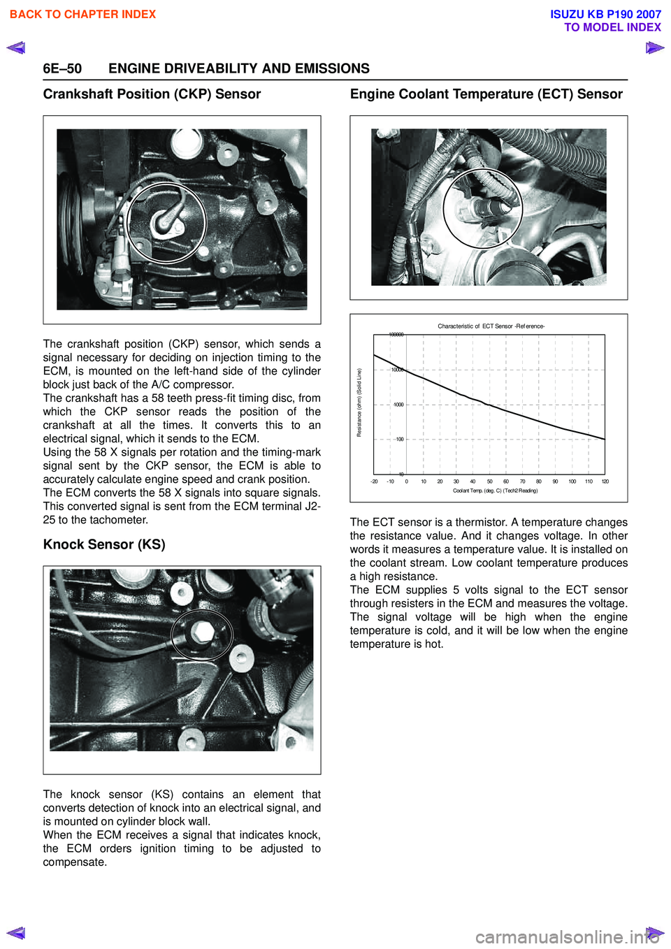
The crankshaft position (CKP) sensor, which sends a
signal necessary for deciding on injection timing to the
ECM, is mounted on the left-hand side of the cylinder
block just back of the A/C compressor.
The crankshaft has a 58 teeth press-fit timing disc, from
which the CKP sensor reads the position of the
crankshaft at all the times. It converts this to an
electrical signal, which it sends to the ECM.
Using the 58 X signals per rotation and the timing-mark
signal sent by the CKP sensor, the ECM is able to
accurately calculate engine speed and crank position.
The ECM converts the 58 X signals into square signals.
This converted signal is sent from the ECM terminal J2-
25 to the tachometer.
Knock Sensor (KS)
The knock sensor (KS) contains an element that
converts detection of knock into an electrical signal, and
is mounted on cylinder block wall.
When the ECM receives a signal that indicates knock,
the ECM orders ignition timing to be adjusted to
compensate.
Engine Coolant Temperature (ECT) Sensor
The ECT sensor is a thermistor. A temperature changes
the resistance value. And it changes voltage. In other
words it measures a temperature value. It is installed on
the coolant stream. Low coolant temperature produces
a high resistance.
The ECM supplies 5 volts signal to the ECT sensor
through resisters in the ECM and measures the voltage.
The signal voltage will be high when the engine
temperature is cold, and it will be low when the engine
temperature is hot.
C harac t eris t ic of ECT Sens or -R ef erenc e-
10
100
1000
10000
100000
-20-100 10203040 5060708090100110120 C ool ant T emp. ( deg . C ) ( Tec h2 R eadi ng )
Resistance (ohm) (Solid Line)
BACK TO CHAPTER INDEX
TO MODEL INDEX
ISUZU KB P190 2007
Page 2221 of 6020
ENGINE DRIVEABILITY AND EMISSIONS 6E–51
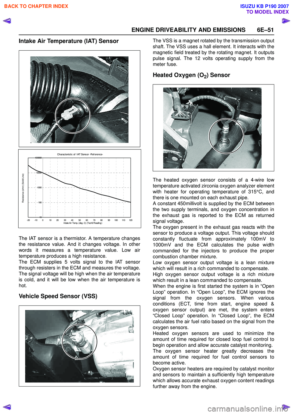
Intake Air Temperature (IAT) Sensor
The IAT sensor is a thermistor. A temperature changes
the resistance value. And it changes voltage. In other
words it measures a temperature value. Low air
temperature produces a high resistance.
The ECM supplies 5 volts signal to the IAT sensor
through resisters in the ECM and measures the voltage.
The signal voltage will be high when the air temperature
is cold, and it will be low when the air temperature is
hot.
Vehicle Speed Sensor (VSS)
The VSS is a magnet rotated by the transmission output
shaft. The VSS uses a hall element. It interacts with the
magnetic field treated by the rotating magnet. It outputs
pulse signal. The 12 volts operating supply from the
meter fuse.
Heated Oxygen (O2) Sensor
The heated oxygen sensor consists of a 4-wire low
temperature activated zirconia oxygen analyzer element
with heater for operating temperature of 315°C, and
there is one mounted on each exhaust pipe.
A constant 450millivolt is supplied by the ECM between
the two supply terminals, and oxygen concentration in
the exhaust gas is reported to the ECM as returned
signal voltage.
The oxygen present in the exhaust gas reacts with the
sensor to produce a voltage output. This voltage should
constantly fluctuate from approximately 100mV to
1000mV and the ECM calculates the pulse width
commanded for the injectors to produce the proper
combustion chamber mixture.
Low oxygen sensor output voltage is a lean mixture
which will result in a rich commanded to compensate.
High oxygen sensor output voltage is a rich mixture
which result in a lean commanded to compensate.
When the engine is first started the system is in “Open
Loop” operation. In “Open Loop”, the ECM ignores the
signal from the oxygen sensors. When various
conditions (ECT, time from start, engine speed &
oxygen sensor output) are met, the system enters
“Closed Loop” operation. In “Closed Loop”, the ECM
calculates the air fuel ratio based on the signal from the
oxygen sensors.
Heated oxygen sensors are used to minimize the
amount of time required for closed loop fuel control to
begin operation and allow accurate catalyst monitoring.
The oxygen sensor heater greatly decreases the
amount of time required for fuel control sensors to
become active.
Oxygen sensor heaters are required by catalyst monitor
and sensors to maintain a sufficiently high temperature
which allows accurate exhaust oxygen content readings
further away from the engine.
Charac t eris t ic of I AT Sens or -R ef erenc e-
10
100
1000
10000
100000
- 20 - 10 0 10 20 30 40 50 60 70 80 90 100 110 120 Intake Ai r T emp. ( deg . C ) ( T ec h2 R eadi ng )
Resistance (ohm) (Solid Line)
BACK TO CHAPTER INDEX
TO MODEL INDEX
ISUZU KB P190 2007
Page 2222 of 6020
6E–52 ENGINE DRIVEABILITY AND EMISSIONS
GENERAL DESCRIPTION FOR FUEL
METERING
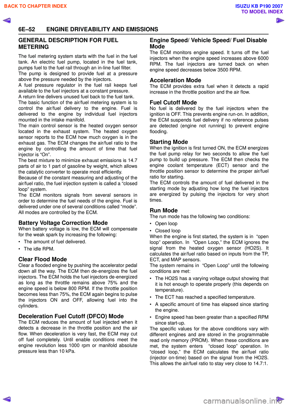
The fuel metering system starts with the fuel in the fuel
tank. An electric fuel pump, located in the fuel tank,
pumps fuel to the fuel rail through an in-line fuel filter.
The pump is designed to provide fuel at a pressure
above the pressure needed by the injectors.
A fuel pressure regulator in the fuel rail keeps fuel
available to the fuel injectors at a constant pressure.
A return line delivers unused fuel back to the fuel tank.
The basic function of the air/fuel metering system is to
control the air/fuel delivery to the engine. Fuel is
delivered to the engine by individual fuel injectors
mounted in the intake manifold.
The main control sensor is the heated oxygen sensor
located in the exhaust system. The heated oxygen
sensor reports to the ECM how much oxygen is in the
exhaust gas. The ECM changes the air/fuel ratio to the
engine by controlling the amount of time that fuel
injector is “On”.
The best mixture to minimize exhaust emissions is 14.7
parts of air to 1 part of gasoline by weight, which allows
the catalytic converter to operate most efficiently.
Because of the constant measuring and adjusting of the
air/fuel ratio, the fuel injection system is called a “closed
loop” system.
The ECM monitors signals from several sensors in
order to determine the fuel needs of the engine. Fuel is
delivered under one of several conditions called “mode”.
All modes are controlled by the ECM.
Battery Voltage Correction Mode
When battery voltage is low, the ECM will compensate
for the weak spark by increasing the following:
• The amount of fuel delivered.
• The idle RPM.
Clear Flood Mode
Clear a flooded engine by pushing the accelerator pedal
down all the way. The ECM then de-energizes the fuel
injectors. The ECM holds the fuel injectors de-energized
as long as the throttle remains above 75% and the
engine speed is below 800 RPM. If the throttle position
becomes less than 75%, the ECM again begins to pulse
the injectors ON and OFF, allowing fuel into the
cylinders.
Deceleration Fuel Cutoff (DFCO) Mode
The ECM reduces the amount of fuel injected when it
detects a decrease in the throttle position and the air
flow. When deceleration is very fast, the ECM may cut
off fuel completely. Until enable conditions meet the
engine revolution less 1000 rpm or manifold absolute
pressure less than 10 kPa.
Engine Speed/ Vehicle Speed/ Fuel Disable
Mode
The ECM monitors engine speed. It turns off the fuel
injectors when the engine speed increases above 6000
RPM. The fuel injectors are turned back on when
engine speed decreases below 3500 RPM.
Acceleration Mode
The ECM provides extra fuel when it detects a rapid
increase in the throttle position and the air flow.
Fuel Cutoff Mode
No fuel is delivered by the fuel injectors when the
ignition is OFF. This prevents engine run-on. In addition,
the ECM suspends fuel delivery if no reference pulses
are detected (engine not running) to prevent engine
flooding.
Starting Mode
When the ignition is first turned ON, the ECM energizes
the fuel pump relay for two seconds to allow the fuel
pump to build up pressure. The ECM then checks the
engine coolant temperature (ECT) sensor and the
throttle position sensor to determine the proper air/fuel
ratio for starting.
The ECM controls the amount of fuel delivered in the
starting mode by adjusting how long the fuel injectors
are energized by pulsing the injectors for very short
times.
Run Mode
The run mode has the following two conditions:
• Open loop
• Closed loop
When the engine is first started, the system is in “open
loop” operation. In “Open Loop,” the ECM ignores the
signal from the heated oxygen sensor (HO2S). It
calculates the air/fuel ratio based on inputs from the TP,
ECT, and MAP sensors.
The system remains in “Open Loop” until the following
conditions are met:
• The HO2S has a varying voltage output showing that it is hot enough to operate properly (this depends on
temperature).
• The ECT has reached a specified temperature.
• A specific amount of time has elapsed since starting the engine.
• Engine speed has been greater than a specified RPM since start-up.
The specific values for the above conditions vary with
different engines and are stored in the programmable
read only memory (PROM). When these conditions are
met, the system enters “closed loop” operation. In
“closed loop,” the ECM calculates the air/fuel ratio
(injector on-time) based on the signal from the HO2S.
This allows the air/fuel ratio to stay very close to 14.7:1.
BACK TO CHAPTER INDEX
TO MODEL INDEX
ISUZU KB P190 2007
Page 2223 of 6020
ENGINE DRIVEABILITY AND EMISSIONS 6E–53
Fuel Metering System Components
The fuel metering system is made up of the following
parts.
• Fuel injector
• Throttle body
•Fuel rail
• Fuel pressure regulator
•ECM
• Crankshaft position (CKP) sensor
• Idle air control (IAC) valve
•Fuel pump
Fuel Injector
The group fuel injection fuel injector is a solenoid
operated device controlled by the ECM. The ECM
energizes the solenoid, which opens a valve to allow
fuel delivery.
The fuel is injected under pressure in a conical spray
pattern at the opening of the intake valve. Excess fuel
not used by the injectors passes through the fuel
pressure regulator before being returned to the fuel
tank.
Fuel Pressure Regulator
The fuel pressure regulator is a diaphragm-operated
relief valve mounted on the fuel rail with fuel pump
pressure on one side and manifold pressure on the
other side. The fuel pressure regulator maintains the
fuel pressure available to the injector at three times
barometric pressure adjusted for engine load. It may be
serviced separately.
If the pressure is too low or poor performance, DTC
P0131 or P1171 will be the result. If the pressure is too
high, DTC P0132 or P1167 will be the result. Refer to
Fuel System Diagnosis for information on diagnosing
fuel pressure conditions.
Fuel Rail
The fuel rail is mounted to the top of the engine and
distributes fuel to the individual injectors. Fuel is
delivered to the fuel inlet tube of the fuel rail by the fuel
lines. The fuel goes through the fuel rail to the fuel
pressure regulator. The fuel pressure regulator
maintains a constant fuel pressure at the injectors.
Remaining fuel is then returned to the fuel tank.
Fuel Pump Electrical Circuit
When the key is first turned ON, the ECM energizes the
fuel pump relay for two seconds to build up the fuel
pressure quickly. If the engine is not started within two
seconds, the ECM shuts the fuel pump off and waits
until the engine is cranked. When the engine is cranked
and the 58X crankshaft position signal has been
detected by the ECM, the ECM supplies 12 volts to the
fuel pump relay to energize the electric in-tank fuel
pump.
An inoperative fuel pump will cause a “no-start”
condition. A fuel pump which does not provide enough pressure will result in poor performance.
Thottle Body Unit
The throttle body has a throttle plate to control the
amount of air delivered to the engine. The Thottle
position sensor and IAC valve are also mounted on the
throttle body.
Vacuum ports located behind the throttle plate provide
the vacuum signals needed by various components.
Engine coolant is directed through a coolant cavity in
the throttle body to warm the throttle valve and to
prevent icing.
BACK TO CHAPTER INDEX
TO MODEL INDEX
ISUZU KB P190 2007
Page 2224 of 6020
6E–54 ENGINE DRIVEABILITY AND EMISSIONS
GENERAL DESCRIPTION FOR ELECTRIC
IGNITION SYSTEM
The engine use two ignition coils, one per two cylinders.
A two wire connector provides a battery voltage primary
supply through the ignition fuse.
The ignition control spark timing is the ECM’s method of
controlling the spark advance and the ignition dwell.
The ignition control spark advance and the ignition dwell
are calculated by the ECM using the following inputs.
• Engine speed
• Crankshaft position (CKP) sensor
• Engine coolant temperature (ECT) sensor
• Throttle position sensor
• Vehicle speed sensor
• ECM and ignition system supply voltage
Ignition coil works to generate only the secondary
voltage be receiving the primary voltage from ECM.
The primary voltage is generated at the coil driver
located in the ECM. The coil driver generate the primary
voltage based on the crankshaft position signal. In
accordance with the crankshaft position signal, ignition
coil driver determines the adequate ignition timing and
also cylinder number to ignite.
Ignition timing is determined the coolant temperature,
intake air temperature, engine speed, engine load,
knock sensor signal, etc.
Spark Plug
Although worn or dirty spark plugs may give satisfactory
operation at idling speed, they frequently fail at higher
engine speeds. Faulty spark plugs may cause poor fuel
economy, power loss, loss of speed, hard starting and
generally poor engine performance. Follow the
scheduled maintenance service recommendations to
ensure satisfactory spark plug performance. Refer to
Maintenance and Lubrication .
Normal spark plug operation will result in brown to
grayish-tan deposits appearing on the insulator portion
of the spark plug. A small amount of red-brown, yellow,
and white powdery material may also be present on the
insulator tip around the center electrode. These
deposits are normal combustion by-products of fuels
and lubricating oils with additives. Some electrode wear
will also occur. Engines which are not running properly
are often referred to as “misfiring.” This means the
ignition spark is not igniting the air/fuel mixture at the
proper time. While other ignition and fuel system causes
must also be considered, possible causes include
ignition system conditions which allow the spark voltage
to reach ground in some other manner than by jumping
across the air gap at the tip of the spark plug, leaving
the air/fuel mixture unburned. Misfiring may also occur
when the tip of the spark plug becomes overheated and
ignites the mixture before the spark jumps. This is
referred to as “pre-ignition.”
Spark plugs may also misfire due to fouling, excessive
gap, or a cracked or broken insulator. If misfiring occurs before the recommended replacement interval, locate
and correct the cause.
Carbon fouling of the spark plug is indicated by dry,
black carbon (soot) deposits on the portion of the spark
plug in the cylinder. Excessive idling and slow speeds
under light engine loads can keep the spark plug
temperatures so low that these deposits are not burned
off. Very rich fuel mixtures or poor ignition system output
may also be the cause. Refer to DTC P1167.
Oil fouling of the spark plug is indicated by wet oily
deposits on the portion of the spark plug in the cylinder,
usually with little electrode wear. This may be caused by
oil during break-in of new or newly overhauled engines.
Deposit fouling of the spark plug occurs when the
normal red-brown, yellow or white deposits of
combustion by-products become sufficient to cause
misfiring. In some cases, these deposits may melt and
form a shiny glaze on the insulator around the center
electrode. If the fouling is found in only one or two
cylinders, valve stem clearances or intake valve seals
may be allowing excess lubricating oil to enter the
cylinder, particularly if the deposits are heavier on the
side of the spark plug facing the intake valve.
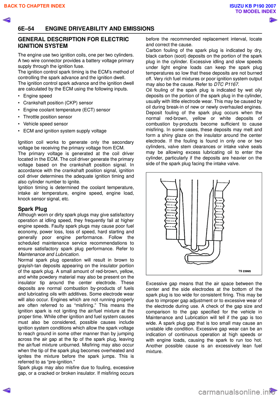
Excessive gap means that the air space between the
center and the side electrodes at the bottom of the
spark plug is too wide for consistent firing. This may be
due to improper gap adjustment or to excessive wear of
the electrode during use. A check of the gap size and
comparison to the gap specified for the vehicle in
Maintenance and Lubrication will tell if the gap is too
wide. A spark plug gap that is too small may cause an
unstable idle condition. Excessive gap wear can be an
indication of continuous operation at high speeds or
with engine loads, causing the spark to run too hot.
Another possible cause is an excessively lean fuel
mixture.
BACK TO CHAPTER INDEX
TO MODEL INDEX
ISUZU KB P190 2007
Page 2233 of 6020
ENGINE DRIVEABILITY AND EMISSIONS 6E–63
3. Check Bulletins and Troubleshooting Hints
NOTE: As estimated 30 percent of successful vehicle
repairs are diagnosed with this step!
What you should do
You should have enough information gained from
preliminary checks to accurately search for a bulletin
and other related service information. Some service
manual sections provide troubleshooting hints that
match symptoms with specific complaints.
What resources you should use
You should use the following resources for assistance in
checking for bulletins and troubleshooting hints:
• Printed bulletins
• Access ISUZU Bulletin Web site.
• Videotapes
• Service manual
4. Perform Service Manual Diagnostic Checks
What you should do
The “System Checks” in most service manual sections
and in most cells of section 8A (electrical) provide you
with:
• A systematic approach to narrowing down the possible causes of a system fault
• Direction to specific diagnostic procedures in the service manual
• Assistance to identify what systems work correctly
What resources you should use
Whenever possible, you should use the following
resources to perform service manual checks:
• Service manual
• Technical equipment (for viewing DTCs and analyzing data)
• Digital multimeter and circuit testing tools
• Other tools as needed
5a and 5b. Perform Service Manual Diagnostic Procedures
NOTE: An estimated 40 percent of successful vehicle
repairs are diagnosed with these steps!
What you should do
When directed by service manual diagnostic checks,
you must then carefully and accurately perform the
steps of diagnostic procedures to locate the fault related to the customer complaint.
What resources you should use
Whenever appropriate, you should use the following
resources to perform service manual diagnostic
procedures:
• Service manual
• Technical equipment (for analyzing diagnostic data)
• Digital multimeter and circuit testing tools
• Essential and special tools
5c. Technician Self Diagnoses
When there is no DTC stored and no matching
symptom for the condition identified in the service
manual, you must begin with a thorough understanding
of how the system(s) operates. Efficient use of the
service manual combined with you experience and a
good process of elimination will result in accurate
diagnosis of the condition.
What you should do
Step 1: Identify and understand the suspect
circuit(s)
Having completed steps 1 through 4 of the Strategy
Based Diagnostics chart, you should have enough
information to identify the system(s) or sub-system(s)
involved. Using the service manual, you should
determine and investigate the following circuit
characteristics:
• Electrical: – How is the circuit powered (power distributioncharts and/or fuse block details)?
– How is the circuit grounded (ground distribution charts)?
– How is the circuit controlled or sensed (theory of operation):
– If it is a switched circuit, is it normally open or normally closed?
– Is the power switched or is the ground switched?
– Is it a variable resistance circuit (ECT sensor or TP sensor, for example)?
– Is it a signal generating device (MAF sensor of VSS, for example)?
– Does it rely on some mechanical/vacuum device to operate?
•Physical:
– Where are the circuit components (componentlocators and wire harness routing diagrams):
– Are there areas where wires could be chafed or pinched (brackets or frames)?
– Are there areas subjected to extreme temperatures?
BACK TO CHAPTER INDEX
TO MODEL INDEX
ISUZU KB P190 2007
Page 2235 of 6020
ENGINE DRIVEABILITY AND EMISSIONS 6E–65
Step 3: Simulate the symptom and isolate the
problem
Simulate the symptom and isolate the system by
reproducing all possible conditions suggested in Step 1
while monitoring suspected circuits/components/
systems to isolate the problem symptom. Begin with the
most logical circuit/component.
Isolate the circuit by dividing the suspect system into
simpler circuits. Next, confine the problem into a smaller
area of the system. Begin at the most logical point (or
point of easiest access) and thoroughly check the
isolated circuit for the fault, using basic circuit tests.
Hints
You can isolate a circuit by:
• Unplugging connectors or removing a fuse to separate one part of the circuit from another
• If only component fails to operate, begin testing the component
• If a number of components do not operate, begin test at areas of commonality (such as power sources,
ground circuits, switches, main connectors or major
components)
• Substitute a known good part from the parts department or the vehicle system
• Try the suspect part in a known good vehicle
See Symptom Simulation Tests on the next page for
problem simulation procedures. Refer to service manual
sections 6E and 8A for information about intermittent
diagnosis. Follow procedures for basic circuit testing in
service manual section 8A.
What resources you should use
Whenever appropriate, you should use the following
resources to assist in the diagnostic process:
• Service manual
• Bulletins
• Digital multimeter (with a MIN/MAX feature)
• Tech II and Tech II upload function
• Circuit testing tools (including connector kits/ harnesses and jumper wires)
• Experience
• Intermittent problem solving simulation methods
• Customer complaint check sheet
Symptom Simulation Tests
1. Vibration
This method is useful when the customer complaint
analysis indicates that the problem occurs when the
vehicle/system undergoes some form of vibration.
For connectors and wire harness, slightly shake
vertically and horizontally. Inspect the connector joint
and body for damage. Also, tapping lightly along a
suspected circuit may be helpful. For parts and sensors, apply slight vibration to the part
with a light tap of the finger while monitoring the system
for a malfunction.
2. Heat
This method is important when the complaint suggests
that the problem occurs in a heated environment. Apply
moderate heat to the component with a hair drier or
similar tool while monitoring the system for a
malfunction.
CAUTION: Care must be take to avoid overheating
the component.
3. Water and Moisture
This method may be used when the complaint suggests
that the malfunction occurs on a rainy day or under
conditions of high humidity. In this case, apply water in a
light spray on the vehicle to duplicate the problem.
CAUTION: Care must be take to avoid directly
exposing electrical connections to water.
4. Electrical loads
This method involves turning systems ON (such as the
blower, lights or rear window defogger) to create a load
on the vehicle electrical system at the same time you
are monitoring the suspect circuit/component.
5e. Vehicle Operates as Designed
This condition refers to instances where a system
operating as designed is perceived to be unsatisfactory
or undesirable. In general, this is due to:
• A lack of understanding by the customer
• A conflict between customer expectations and vehicle design intent
• A system performance that is unacceptable to the customer
What you should do
You can verify that a system is operating as designed
by:
• Reviewing service manual functional/diagnostic checks
• Examining bulletins and other service information for supplementary information
• Compare system operation to an identical vehicle
If the condition is due to a customer misunderstanding
or a conflict between customer expectation and system
operation, you should explain the system operation to
the customer.
If the complaint is due to a case of unsatisfactory
system performance, you should contact Technical
Assistance for the latest information.
What resources you should use
Whenever possible, you should use the following
resources to facilitate the diagnostic process:
BACK TO CHAPTER INDEX
TO MODEL INDEX
ISUZU KB P190 2007