sensor ISUZU KB P190 2007 Workshop Repair Manual
[x] Cancel search | Manufacturer: ISUZU, Model Year: 2007, Model line: KB P190, Model: ISUZU KB P190 2007Pages: 6020, PDF Size: 70.23 MB
Page 2178 of 6020

6E–8 ENGINE DRIVEABILITY AND EMISSIONS
1234
(1)
(2) Injector #1 Cylinder
Injector #2 Cylinder (3)
(4) Injector #3 Cylinder
Injector #4 Cylinder (Under the ECM)
(1) Ignition Coil Module Assembly
(1) Heated Oxygen Sensor (HO2S)
BACK TO CHAPTER INDEX
TO MODEL INDEX
ISUZU KB P190 2007
Page 2179 of 6020

ENGINE DRIVEABILITY AND EMISSIONS 6E–9
(1) Crankshaft Position (CKP) Sensor(1) Knock Sensor (KS)
(1)
(2) Engine Coolant Temperature (ECT) Sensor
Thermo Meter Sensor
21
(1) Manifold Absolute Pressure (MAP) Sensor
(1)
(2) Throttle Position Sensor
Idle Air Control (IAC) Valve
2
1
(1) EVAP Purge Solenoid
BACK TO CHAPTER INDEX
TO MODEL INDEX
ISUZU KB P190 2007
Page 2180 of 6020

6E–10 ENGINE DRIVEABILITY AND EMISSIONS
(1) Canister(1)
(2) Fuel Tank
Fuel Pump
2
1
(1)
(2) Vehicle Speed Sensor (VSS)
Transmission Assembly
12
(1)
(2) Power Steering Pressure Switch
Power Steering Oil Pump Assembly
12
BACK TO CHAPTER INDEX
TO MODEL INDEX
ISUZU KB P190 2007
Page 2198 of 6020

6E–28 ENGINE DRIVEABILITY AND EMISSIONS
CONNECTOR LIST
No.Connector face No.Connector face
B-24
Green Meter-B C-122
CO Adjuster
B-58
Black Check connector E-6
Fuel injector
B-62
White Ignition switch (IGSUB : G1) E-7
Fuel injector
B-63
White Ignition switch (IGSUB : G2) E-8
Fuel injector
B-68
Immobilizer E-9
Fuel injector
C-2
Silver Engine room-RH ground E-18
Ignition coil
C-56
ECM E-60
ECM
C-107
White J/B E2 E-72
Engine earth-A
C-108
White J/B E1 E-74
Engine earth-B
C-121
IAT sensor E-77
O
2 sensor
BACK TO CHAPTER INDEX
TO MODEL INDEX
ISUZU KB P190 2007
Page 2199 of 6020

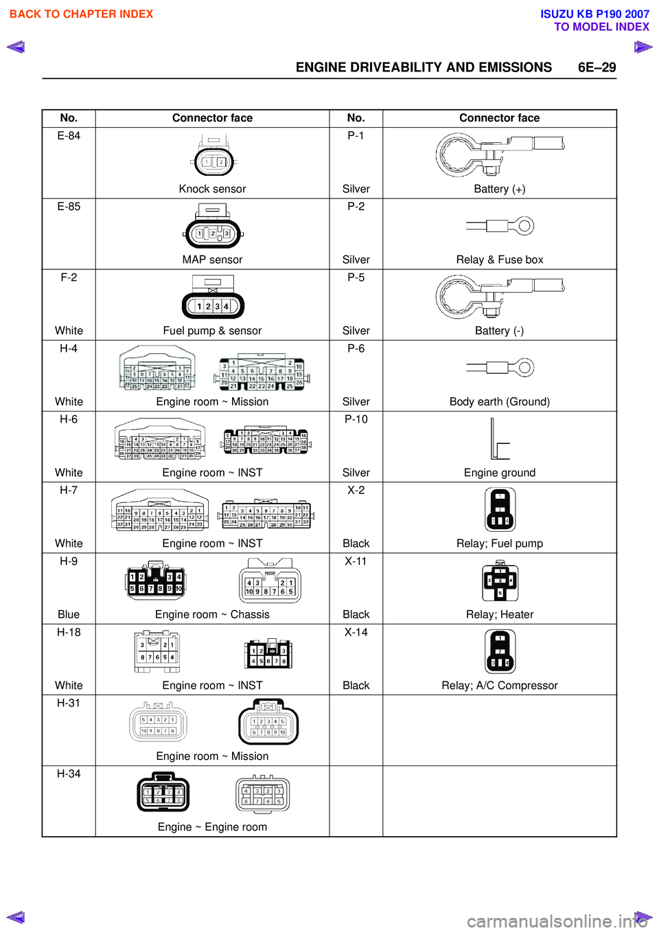
ENGINE DRIVEABILITY AND EMISSIONS 6E–29
No.Connector face No.Connector face
E-84
Knock sensor P-1
Silver Battery (+)
E-85
MAP sensor P-2
Silver Relay & Fuse box
F-2
White Fuel pump & sensor P-5
Silver Battery (-)
H-4
White Engine room ~ Mission P-6
Silver Body earth (Ground)
H-6
White Engine room ~ INST P-10
Silver Engine ground
H-7
White Engine room ~ INST X-2
Black Relay; Fuel pump
H-9
Blue Engine room ~ Chassis X-11
Black Relay; Heater
H-18
White Engine room ~ INST X-14
Black Relay; A/C Compressor
H-31
Engine room ~ Mission
H-34
Engine ~ Engine room
BACK TO CHAPTER INDEX
TO MODEL INDEX
ISUZU KB P190 2007
Page 2201 of 6020

ENGINE DRIVEABILITY AND EMISSIONS 6E–31
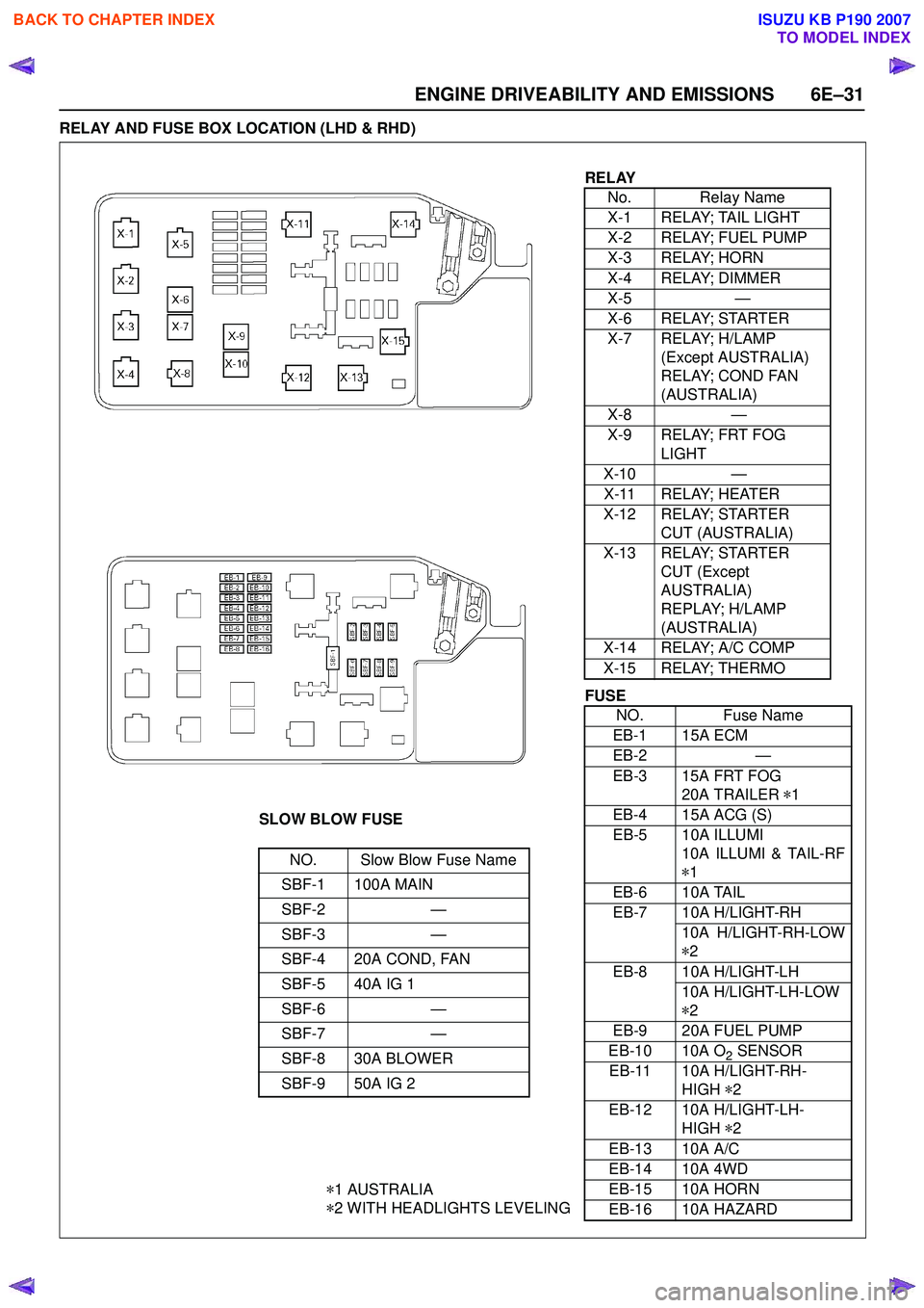
RELAY AND FUSE BOX LOCATION (LHD & RHD)
RELAYNo. Relay Name
X-1 RELAY; TAIL LIGHT
X-2 RELAY; FUEL PUMP
X-3 RELAY; HORN
X-4 RELAY; DIMMER
X-5 —
X-6 RELAY; STARTER
X-7 RELAY; H/LAMP (Except AUSTRALIA)
RELAY; COND FAN
(AUSTRALIA)
X-8 —
X-9 RELAY; FRT FOG LIGHT
X-10 —
X-11 RELAY; HEATER
X-12 RELAY; STARTER CUT (AUSTRALIA)
X-13 RELAY; STARTER CUT (Except
AUSTRALIA)
REPLAY; H/LAMP
(AUSTRALIA)
X-14 RELAY; A/C COMP
X-15 RELAY; THERMO
SLOW BLOW FUSE
NO. Slow Blow Fuse Name
SBF-1 100A MAIN
SBF-2 —
SBF-3 —
SBF-4 20A COND, FAN
SBF-5 40A IG 1
SBF-6 —
SBF-7 —
SBF-8 30A BLOWER
SBF-9 50A IG 2
* 1 AUSTRALIA
* 2 WITH HEADLIGHTS LEVELING
FUSE
NO. Fuse Name
EB-1 15A ECM
EB-2 —
EB-3 15A FRT FOG 20A TRAILER *1
EB-4 15A ACG (S)
EB-5 10A ILLUMI 10A ILLUMI & TAIL-RF
* 1
EB-6 10A TAIL
EB-7 10A H/LIGHT-RH 10A H/LIGHT-RH-LOW
* 2
EB-8 10A H/LIGHT-LH 10A H/LIGHT-LH-LOW
* 2
EB-9 20A FUEL PUMP
EB-10 10A O
2 SENSOR
EB-11 10A H/LIGHT-RH- HIGH *2
EB-12 10A H/LIGHT-LH- HIGH *2
EB-13 10A A/C
EB-14 10A 4WD
EB-15 10A HORN
EB-16 10A HAZARD
BACK TO CHAPTER INDEX
TO MODEL INDEX
ISUZU KB P190 2007
Page 2212 of 6020

6E–42 ENGINE DRIVEABILITY AND EMISSIONS
ECM CONNECTOR PIN ASSIGNMENT & OUTPUT SIGNAL
Connector J1 Port: View Looking Into ECM Case
1
17 16
32
PIN16
PIN1
PIN17 PIN32
Pin
No. B/
Box
No. Pin Function
Wire
Color Signal or Continuity
ECM
Connection Tester Position
Key SW Off Key SW
On Engine
Idle Engine
2000rpm Range (+) (-)
J1-1 J1-1 Ground BLK/
WHT Continuity
with
ground -
- - Disconnect ΩJ1-1 GND
J1-2 J1-2 Ground BLK/
WHT Continuity
with
ground -
- - Disconnect ΩJ1-2 GND
J1-3 J1-3 Knock Sensor Signal YEL Less than 1V--- ----
J1-4 J1-4 No Connection - --- - -- - -
J1-5 J1-5 Canister Purge Solenoid Valve RED/
YEL Less than
1V Wave form G or 12-14V
Connect DC V J1-5 GND
J1-6 J1-6 Crankshaft Position (CKP) Sensor (Ground) RED Approx.
0.58kΩ -
- - Disconnect ΩJ1-6 J1-21
J1-7 J1-7 Throttle Position Sensor (TPS) Output
Signal BLU Less than
1V Approx 0.7V Approx
0.8VConnect DC V J1-7 J1-32
J1-8 J1-8 No. 3 Injector GRN/
BLK Less than
1V Wave form E or 12-14V
Connect DC V J1-8 GND
J1-9 J1-9 No. 1 Injector GRN/
WHT Less than
1V Wave form E or 12-14V
Connect DC V J1-9 GND
J1-10 J1-10 No Connection - --- - -- - -
J1-11 J1-11 No. 4 Injector GRN Less than
1V Wave form E or 12-14V
Connect DC V J1-11 GND
J1-12 J1-12 No Connection - --- - -- - -
J1-13 J1-13 Idle Air Control Valve (IACV) Coil B High BLU/
RED Less than
1V Less than 1V / 10-14V
Connect DC V J1-13 GND
J1-14 J1-14 No Connection - --- - -- - -
J1-15 J1-15 Throttle Position Sensor (TPS) Power
Supply RED Less than
1V Approx. 5V
Connect DC V J1-15 J1-32
J1-16 J1-16 MAP Sensor Ground GRN Continuity with
ground -
- - Connect ΩJ1-16 GND
J1-17 J1-17 Ground BLK/
WHT Continuity
with
ground -
- - Connect ΩJ1-17 GND
J1-18 J1-18 Coil Module 2 (No. 2 & 3 Cylinder) BLU -
-Wave form F -- - -
J1-19 J1-19 Coil Module 1 (No. 1 & 4 Cylinder) GRN -
-Wave form F -- - -
J1-20 J1-20 No Connection - --- - -- - -
BACK TO CHAPTER INDEX
TO MODEL INDEX
ISUZU KB P190 2007
Page 2213 of 6020

ENGINE DRIVEABILITY AND EMISSIONS 6E–43
J1-21 J1-21 Crankshaft Position (CKP) Sensor Signal WHT - - Wave form
or approx. 3.7V Wave form
A or
approx. 7.8V Connect AC V J1-21 J1-6
J1-22 J1-22 No.2 Injector GRN/
WHT Less than
1V Wave form E or 12-14V
Connect DC V J1-22 GND
J1-23 J1-23 No Connection - --- - -- - -
J1-24 J1-24 MAP Sensor Signal GRY Less than 1VApprox.
4.8V Approx.
1.3V Approx.
0.9V Connect DC V J1-24 J1-16
J1-25 J1-25 No Connection - --- - -- - -
J1-26 J1-26 No Connection - --- - -- J1-26 -
J1-27 J1-27 Engine Coolant Temp. (ECT) Sensor Signal GRY Less than
1V
20℃: Approx. 2.4V / 40 ℃: Approx. 1.4V or
4.1V / 60 ℃: Approx. 3.3V / 80 ℃: Approx.
2.5VConnect DC V J1-27 J1-32
J1-28 J1-28 Idle Air Control Valve (IACV) Coil A High BLU Less than
1V Less than 1V / 10-14V
Connect DC V J1-28 GND
J1-29 J1-29 Idle Air Control Valve (IACV) Coil B Low BLU/
BLK Less than
1V Less than 1V / 10-14V
Connect DC V J1-29 GND
J1-30 J1-30 Idle Air Control Valve (IACV) Coil A Low BLU/
WHT Less than
1V Less than 1V / 10-14V
Connect DC V J1-30 GND
J1-31 J1-31 MAP Sensor Power Supply RED Less than
1V Approx.. 5V
Connect DC V J1-31 J1-16
J1-32 J1-32 ECT Sensor, Knock Sensor, Throttle
Position Sensor Ground GRN Continuity
with
ground -
- - Connect ΩJ1-32 GND
Pin
No. B/
Box No. Pin Function
Wire
Color Signal or Continuity
ECM
Connection Tester Position
Key SW Off Key SW
On Engine
Idle Engine
2000rpm Range (+) (-)
BACK TO CHAPTER INDEX
TO MODEL INDEX
ISUZU KB P190 2007
Page 2214 of 6020

6E–44 ENGINE DRIVEABILITY AND EMISSIONS
Connector J2 Port: View Looking Into ECM Case
1
17 16
32
PIN32
PIN1
PIN17
PIN16
Pin
No. B/
Box No. Pin Function
Wire
Color Signal or Continuity
ECM
Connection Tester Position
Key SW Off Key SW
On Engine
Idle Engine
2000rpm Range (+) (-)
J2-1 J2-1 Intake Air Temp. (IAT) Sensor Ground GRN Continuity
with
ground -
- - Disconnect ΩJ2-1 GND
J2-2 J2-2 Battery Power Supply RED/ WHT10-14V
Connect DC V J2-2 GND
J2-3 J2-3 Ignition Power Supply BLU/ YELLess than
1V 10-14V
Connect DC V J2-3 GND
J2-4 J2-4 To Data Link Connector No. 6 BLU -
-- - -- - -
J2-5 J2-5 No Connection -- - - - -- - -
J2-6 J2-6 Oxygen Sensor (Ground) PNK Continuity
with
ground -
- - Connect ΩJ2-6 GND
J2-7 J2-7 No Connection -- - - - -- - -
J2-8 J2-8 No Connection -- - - - -- - -
J2-9 J2-9 No Connection -- - - - -- - -
J2-10 J2-10 CO Adjust Signal (W/O Catalystic
Converter) YEL -
-- - -- - -
J2-11 J2-11 Fuel Pump Relay GRN/ WHT10-14V
While relay
is activated; 10-14V
Relay is not
activated;
Less than 1V10-14V Connect DC V J2-11 GND
J2-12 J2-12 No Connection -- - - - -- - -
J2-13 J2-13 A/C Compressor Relay GRY/
RED Less than
1V A/C comp. is operated: Less than 1V
A/C comp. is not operated: 10-14V Connect DC V J2-13 GND
J2-14 J2-14 No Connection -- - - - -- - -
J2-15 J2-15 No Connection -- - - - -- - -
J2-16 J2-16 No Connection -- - - - -- - -
J2-17 J2-17 CO Adjust (W/O Catalystic Converter) RED -
-- - -- - -
J2-18 J2-18 Battery Power Supply RED/ WHT10-14V
Connect DC V J2-18 GND
J2-19 J2-19 No Connection -- - - - -- - -
J2-20 J2-20 Power Steering Pressure Switch GRN/
YEL Less than
1V
Pressure switch is turned on: Less than 1VPressure switch is turned off: 10-14VConnect DC V J2-20 GND
J2-21 J2-21 Oxygen Sensor BLU Less than 1VApprox.
0.4V Wave form D or 0.1 -
0.9V Connect DC V J2-21 J2-6
J2-22 J2-22 Intake Air Temp. (IAT) Sensor (Signal) YEL/
GRN Less than
1V
20℃: Approx. 2.9V / 40 ℃: Approx. 1.8V V
/ 60 ℃: Approx. 1.1V / 80 ℃: Approx. 0.6VConnect DC V J2-22 33
BACK TO CHAPTER INDEX
TO MODEL INDEX
ISUZU KB P190 2007
Page 2215 of 6020

ENGINE DRIVEABILITY AND EMISSIONS 6E–45
J2-23 J2-23 Vehicle Speed Sensor (VSS) Signal
(Immobilizer Control
Unit Terminal B8) WHT -
- Wave form C or Approx.
6.5V at 20km/h Connect AC V J2-23 GND
J2-24 J2-24 No Connection -- - - - -- - -
J2-25 J2-25 Tachometer Output Signal BLK/
RED -
- Wave form Wave form
B or
Approx.
4.5V Connect AC V J2-25 GND
J2-26 J2-26 Thermo Relay GRN/
BLK Less than
1V
A/C request is activated: 10-14V
A/C request is not activated: Less than 1VConnect DC V J2-26 GND
J2-27 J2-27 No Connection - - - - - - - - -
J2-28 J2-28 No Connection - - - - - - - - -
J2-29 J2-29 No Connection -- - - - -- - -
J2-30 J2-30 To Data Link Connector No. 2 GRN -
-- - -- - -
J2-31 J2-31 Oxygen Sensor Heater BLU/ WHTContinuity
with
ground - Wave
Form Wave
Form D Connect
ΩJ2-31 GND
J2-32 J2-32 Check Engine Lamp (Immobilizer Control
Unit Terminal B7) BRN/
YEL Less than
1V Less than
1V Lamp is turned on: Less
than 1V
Lamp is turned off: 10-
14V Connect DC V J2-32 GND
Pin
No. B/
Box No. Pin Function
Wire
Color Signal or Continuity
ECM
Connection Tester Position
Key SW Off Key SW
On Engine
Idle Engine
2000rpm Range (+) (-)
BACK TO CHAPTER INDEX
TO MODEL INDEX
ISUZU KB P190 2007