lock ISUZU KB P190 2007 Workshop Repair Manual
[x] Cancel search | Manufacturer: ISUZU, Model Year: 2007, Model line: KB P190, Model: ISUZU KB P190 2007Pages: 6020, PDF Size: 70.23 MB
Page 3193 of 6020
Engine Cooling – V6 Engine Page 6B1–58
Repair Method
Repairs to the aluminium radiator core should only be made using the recommended 'Aluminised Silicon' based liquid
repair agent, in accordance with the recommended procedure outlined in General Core Repair in this Section. Refer to
the current Partfinder™ for Aluminised Silicon base liquid part number.
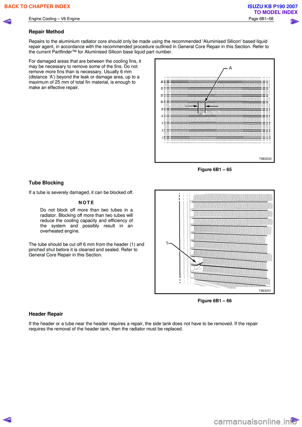
For damaged areas that are between the cooling fins, it
may be necessary to remove some of the fins. Do not
remove more fins than is necessary. Usually 6 mm
(distance ‘A’) beyond the leak or damage area, up to a
maximum of 25 mm of total fin material, is enough to
make an effective repair.
Figure 6B1 – 65
Tube Blocking
If a tube is severely damaged, it can be blocked off.
NOTE
Do not block off more than two tubes in a
radiator. Blocking off more than two tubes will
reduce the cooling capacity and efficiency of
the system and possibly result in an
overheated engine.
The tube should be cut off 6 mm from the header (1) and
pinched shut before it is cleaned and sealed. Refer to
General Core Repair in this Section.
Figure 6B1 – 66
Header Repair
If the header or a tube near the header requires a repair, the side tank does not have to be removed. If the repair
requires the removal of the header tank, then the radiator must be replaced.
BACK TO CHAPTER INDEX
TO MODEL INDEX
ISUZU KB P190 2007
Page 3194 of 6020
Engine Cooling – V6 Engine Page 6B1–59
General Core Repair
NOTE
The need for careful preparation of the surface in
the repair area cannot be over-emphasised. If the
leak area surface is not clean, the repair material
will not adhere to the surface.
Refer to ‘
‘‘
‘
Environmental Issues ’
’’
’
in 3.1
Service Notes, before draining the coolant.
1 Drain the coolant from the system. Refer to 3.3 Draining and Filling Cooling System in this Section.
2 Remove the radiator. Refer to 3.15 Radiator in this Section.
3 If necessary, carefully cut away fins to expose the damaged area.
NOTE
Do not cut away more than 25 mm total fin
material.
4 Clean away dirt etc. with water. Dry the affected area using hot air from a hair drier.
Do not apply flame to dry damaged area.
5 Clean affected area with petrol to remove any traces of oil.
6 Thoroughly stir contents of repair agent.
NOTE
In cases of extended shelf life, the silicon in
solution may separate from the thinner base.
Should this occur, mix contents well until agent is
again homogeneous.
7 Apply repair agent sparingly to damaged area. Do not apply an excessive amount, as this will cause blockage of the radiator tube.
NOTE
Use a clean, dry wooden applicator to 'DRIP'
agent onto damaged area of radiator.
8 Allow radiator to stand in a clean, dry area for a minimum of 3 hours (at ambient temperature of 20 – 30 ° C) with
adequate ventilation.
NOTE
Do not apply heat or flame to promote drying.
9 Reinstall the radiator. Refer to 3.15 Radiator in this Section.
BACK TO CHAPTER INDEX
TO MODEL INDEX
ISUZU KB P190 2007
Page 3195 of 6020
Engine Cooling – V6 Engine Page 6B1–60
Transmission Oil Cooler Leak Test
If the transmission oil cooler is suspected of leaking oil, test it before the radiator is replaced, as follows:
1 Disconnect oil cooler pipes at the flexible hose connections. Refer to 3.14 Flexible Transmission Cooler Hose, in this Section.
2 Plug one of the connections, using a blocked pipe fitting and attach an air supply to the other flexible hose.
3 Remove coolant filler cap and check that the coolant is filled to the coolant filler cap filler neck.
4 Apply air pressure gradually, increasing up to an absolute maximum of 110 kPa. If bubbles appear in radiator neck, the oil cooler is leaking and the radiator assembly must be replaced.
Transmission Oil Cooler Seal Replacement.
It is strongly recommended that the transmission oil cooler connector fittings to the right-hand side radiator header tank,
not be disturbed. If coolant is found to leak from either of these two areas, then the radiator should be replaced.
BACK TO CHAPTER INDEX
TO MODEL INDEX
ISUZU KB P190 2007
Page 3198 of 6020
Engine Cooling – V6 Engine Page 6B1–63
4.5 Problems Not Requiring Disassembly of
Cooling System
1 Large obstructions blocking radiator or condenser airflow.
• Auxiliary oil coolers
• License plate
• Obstruction of radiator grille, for example, driving lights or mud
2 Loose, damaged or missing air chute side panels.
3 Missing or damaged air baffle.
4 Cracked or loose coolant recovery system hose.
5 Leaking heater component such as the heater core or water valve.
4.6 Problems Requiring Disassembly of Cooling System
1 Damaged cooling fan or faulty motor operation.
2 Pressure test cooling system.
3 Defective coolant pump.
• Eroded or broken impeller vanes
• Failed bearing or seal – check for shaft or bearing end play
4 Internally blocked radiator core.
5 Obstruction of coolant recovery system.
6 Internal system leaks.
• Head gaskets
• Cracked cylinder block
• Engine front cover
• Intake manifold gaskets
7 Blocked coolant passages in cylinder heads or block – remove cylinder heads and check.
4.7 Black Light and Dye Leak Diagnosis Method
It is strongly recommended that this diagnostic method be used to diagnose fluid leaks. This method is a proven and
reliable method that identifies the specific leak source.
The black light kit can be used for the leak detection of a number of fluids, when used with the appropriate tracer dye.
Examples are: Coolant, Engine Oil, Automatic Transmission Fluid and Air Conditioning Refrigerant (R134A).
The following is a summary of the steps involved in detecting a cooling system fluid leak using black light and dye:
1 Pour specified amount of dye into the cooling system via the coolant filler cap on the outlet housing. Refer 3.1 Service Notes in this Section.
2 Road test the vehicle under normal operating conditions.
3 Direct the light towards the suspect area. The fluid leak will appear as a brightly coloured path leading from the source.
4 Repair fluid leak and recheck to ensure that leak has been rectified.
5 Refer to the manufacturer’s directions when using this method.
BACK TO CHAPTER INDEX
TO MODEL INDEX
ISUZU KB P190 2007
Page 3200 of 6020
Engine Cooling – V6 Engine Page 6B1–65
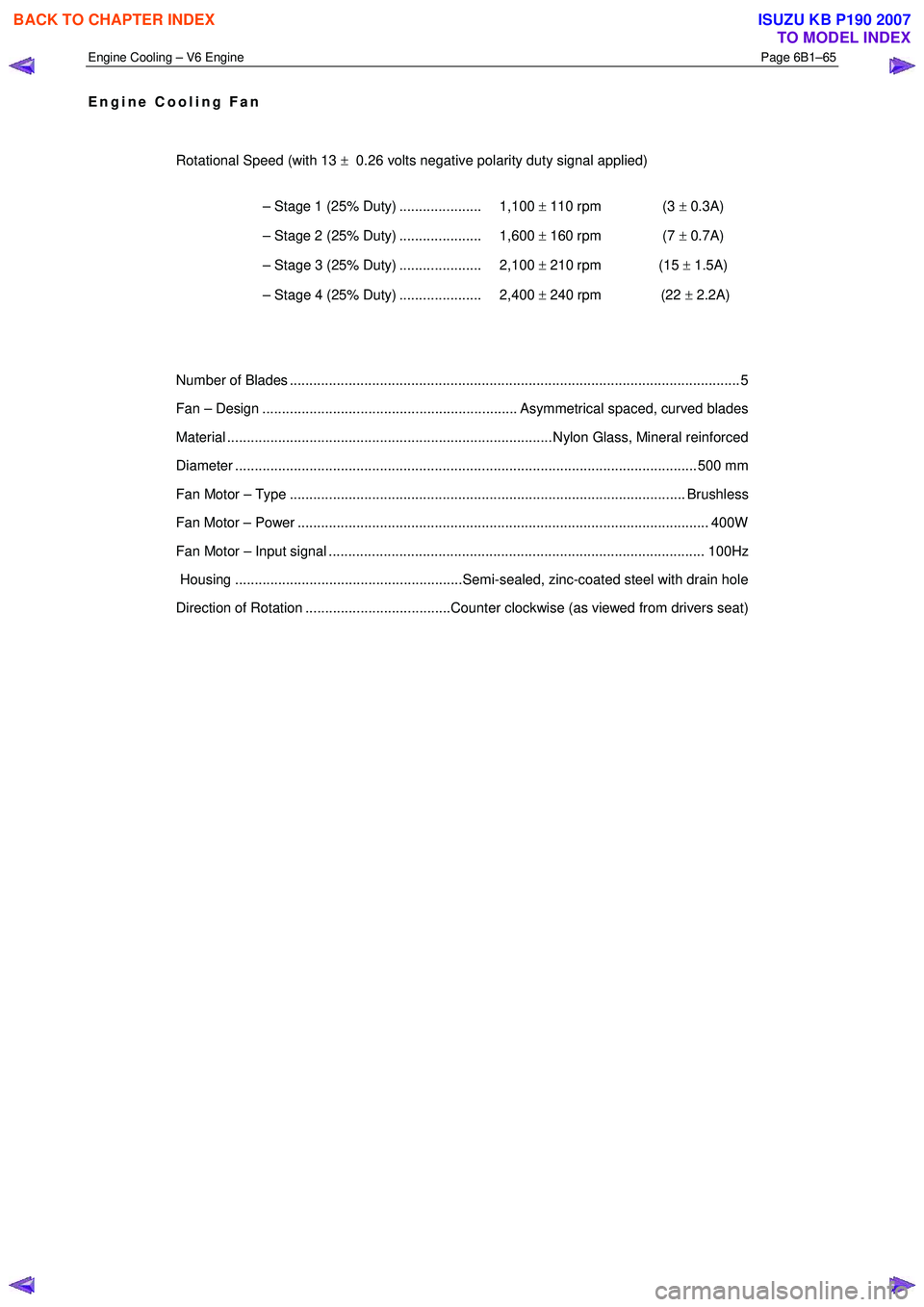
Engine Cooling Fan
Rotational Speed (with 13 ± 0.26 volts negative polarity duty signal applied)
– Stage 1 (25% Duty) ..................... 1,100 ± 110 rpm (3 ± 0.3A)
– Stage 2 (25% Duty) ..................... 1,600 ± 160 rpm (7 ± 0.7A)
– Stage 3 (25% Duty) ..................... 2,100 ± 210 rpm (15 ± 1.5A)
– Stage 4 (25% Duty) ..................... 2,400 ± 240 rpm (22 ± 2.2A)
Number of Blades ............................................................................................................... .... 5
Fan – Design ................................................................. Asymmetrical spaced, curved blades
Material ................................................................................... Nylon Glass, Mineral reinforced
Diameter ...................................................................................................................... 5 00 mm
Fan Motor – Type ..................................................................................................... Brushless
Fan Motor – Power ......................................................................................................... 400W
Fan Motor – Input signal ................................................................................................ 100Hz
Housing ..........................................................Semi-sealed, zinc-coated steel with drain hole
Direction of Rotation .....................................Counter clockwise (as viewed from drivers seat)
BACK TO CHAPTER INDEX
TO MODEL INDEX
ISUZU KB P190 2007
Page 3201 of 6020
Engine Cooling – V6 Engine Page 6B1–66
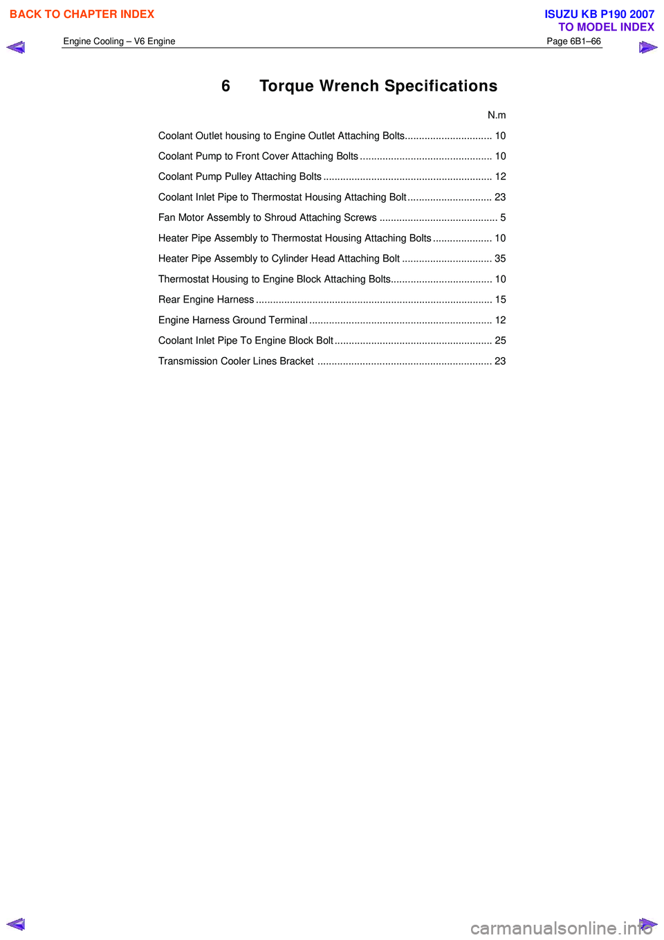
6 Torque Wrench Specifications
N.m
Coolant Outlet housing to Engine Outlet Attaching Bolts............................... 10
Coolant Pump to Front Cover Attaching Bolts ............................................... 10
Coolant Pump Pulley Attaching Bolts ............................................................ 12
Coolant Inlet Pipe to Thermostat Housing Attaching Bolt .............................. 23
Fan Motor Assembly to Shroud Attaching Screws .......................................... 5
Heater Pipe Assembly to Thermostat Housing Attaching Bolts ..................... 10
Heater Pipe Assembly to Cylinder Head Attaching Bolt ................................ 35
Thermostat Housing to Engine Block Attaching Bolts.................................... 10
Rear Engine Harness .................................................................................... 15
Engine Harness Ground Terminal ................................................................. 12
Coolant Inlet Pipe To Engine Block Bolt ........................................................ 25
Transmission Cooler Lines Bracket .............................................................. 23
BACK TO CHAPTER INDEX
TO MODEL INDEX
ISUZU KB P190 2007
Page 3218 of 6020
Fuel System – V6 Page 6C – 16
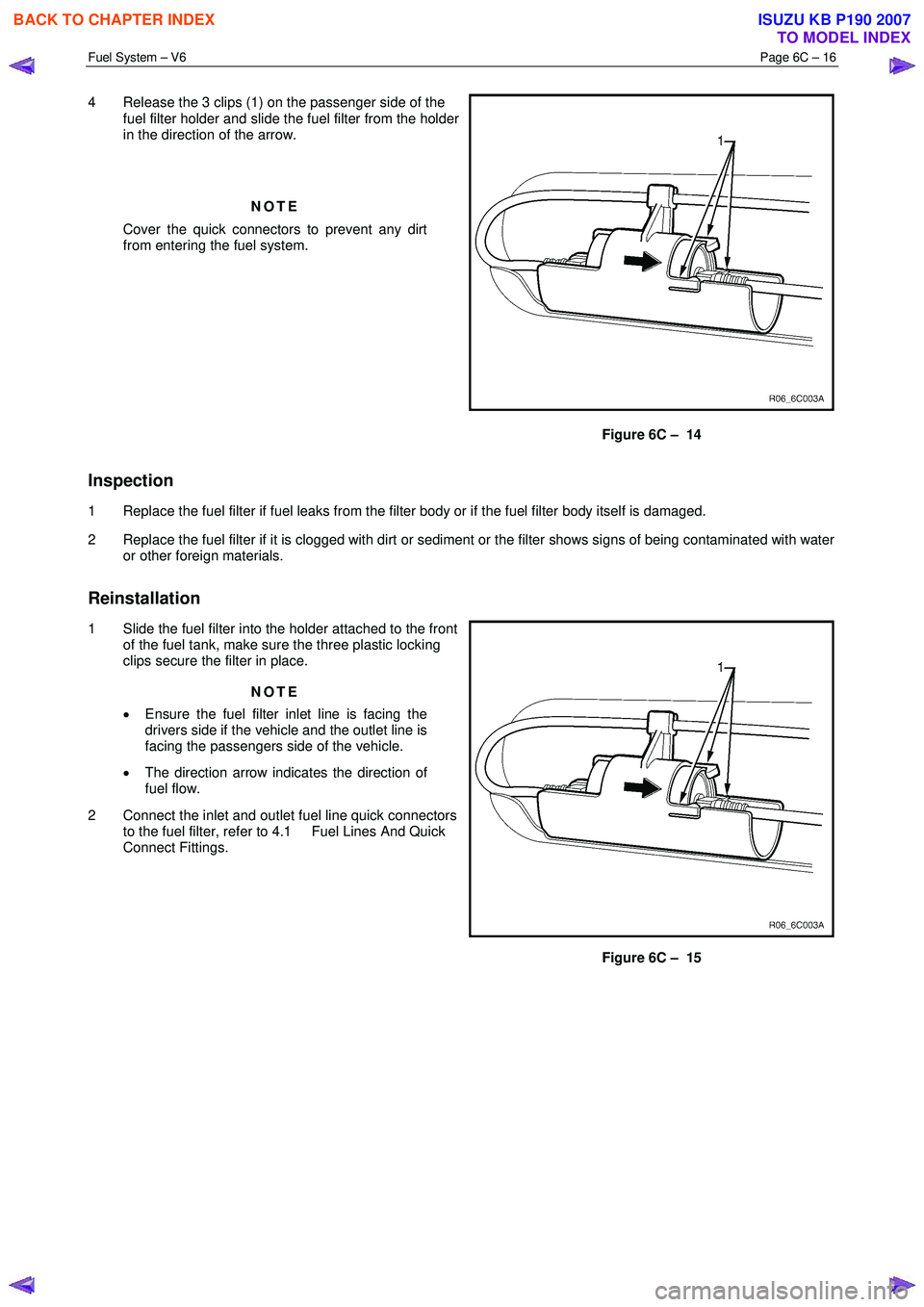
4 Release the 3 clips (1) on the passenger side of the
fuel filter holder and slide the fuel filter from the holder
in the direction of the arrow.
NOTE
Cover the quick connectors to prevent any dirt
from entering the fuel system.
Figure 6C – 14
Inspection
1 Replace the fuel filter if fuel leaks from the filter body or if the fuel filter body itself is damaged.
2 Replace the fuel filter if it is clogged with dirt or sediment or the filter shows signs of being contaminated with water or other foreign materials.
Reinstallation
1 Slide the fuel filter into the holder attached to the front of the fuel tank, make sure the three plastic locking
clips secure the filter in place.
NOTE
• Ensure the fuel filter inlet line is facing the
drivers side if the vehicle and the outlet line is
facing the passengers side of the vehicle.
• The direction arrow indicates the direction of
fuel flow.
2 Connect the inlet and outlet fuel line quick connectors to the fuel filter, refer to 4.1 Fuel Lines And Quick
Connect Fittings.
Figure 6C – 15
BACK TO CHAPTER INDEX
TO MODEL INDEX
ISUZU KB P190 2007
Page 3219 of 6020
Fuel System – V6 Page 6C – 17
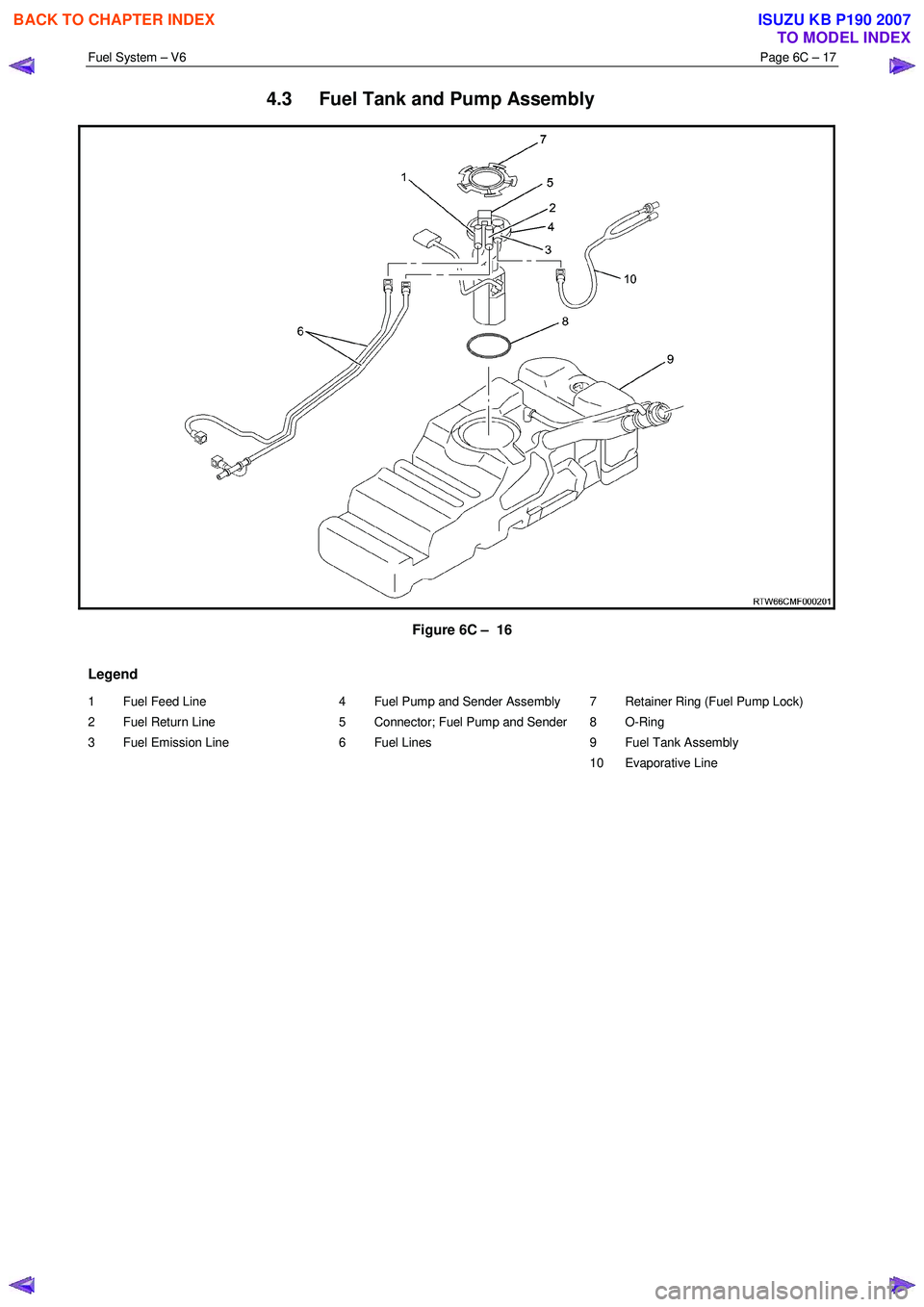
4.3 Fuel Tank and Pump Assembly
Figure 6C – 16
Legend
1 Fuel Feed Line
2 Fuel Return Line
3 Fuel Emission Line
4 Fuel Pump and Sender Assembly
5 Connector; Fuel Pump and Sender
6 Fuel Lines
7 Retainer Ring (Fuel Pump Lock)
8 O-Ring
9 Fuel Tank Assembly
10 Evaporative Line
BACK TO CHAPTER INDEX
TO MODEL INDEX
ISUZU KB P190 2007
Page 3224 of 6020
Fuel System – V6 Page 6C – 22
Reinstall
Reinstallation of the fuel tank is the reverse of the removal procedure, noting the following:
1 Lift the fuel tank into position reinserting the fuel tank inlet and breather hoses into the body opening. Raise the fuel tank into place and rest the front of the tank on the crossmember.
2 Replace the fuel pump electrical connector, be sure to engage the locking tab.
3 Fit the fuel tank mounting straps in the following order, refer to Figure 6C – 17, a Loosely reattach the rear fuel tank mounting strap and bolt (8 & 9), refer to Figure 6C – 17.
b Loosely attach the front mounting strap and bolt (1 & 2), refer to Figure 6C – 17.
c Ensure that the fuel tank is located in the correct position then,
d Tighten the rear mounting strap bolt (8), Figure 6C – 17.
e Tighten the front mounting strap bolt (1), Figure 6C – 17.
4 Tighten all fuel tank mounting strap bolts to the correct torque specification.
Fuel tank mounting strap bolts
torque specification ............................................68.0 Nm
Install the fuel filter with the flow arrow on its
body pointing in the same direction as the
fuel flow to the front of the vehicle.
5 Install the disconnected quick-connect fittings to the fuel supply line at the front of the fuel tank and the evaporative line quick-connect fitting at the rear of the fuel tank. Refer to 4.1 Fuel Lines And Quick Connect Fittings, for the
correct component routeing.
6 Lower the vehicle to a comfortable working height and reinstall the clamp (1) to the fuel filler neck and reconnect the rubber fuel tank inlet hose (2) and tighten the clamp, refer to Figure 6C – 21.
7 Reinstall the fuel tank breather hose (3) to the fuel filler neck (1) and tighten the clamp (2), refer to Figure 6C – 20.
8 Clip the fuel filler door release cable (1) to the retainer on the fuel filler neck (2), refer to Figure 6C – 19.
9 Locate the fuel filler neck (3) to the filler pocket and attach with the securing screw (2), remove the cover material from the fuel filler neck inlet and refit the fuel filler cap (4), refer to Figure 6C – 18.
10 Reinstall the front half of the right-hand rear wheelhouse liner, refer to 10 Cab.
11 Before starting the vehicle, perform a fuel system leak test, refer to 3.3 Fuel Leak Test.
BACK TO CHAPTER INDEX
TO MODEL INDEX
ISUZU KB P190 2007
Page 3225 of 6020
Fuel System – V6 Page 6C – 23
4.5 Modular Fuel Pump and Sender
Assembly
NOTE
If the modular fuel pump and sender assembly
develops a fault it must be replaced as a
complete unit. The only serviced parts are the
retainer locking ring and the O-ring seal.
Remove
• A depressurised fuel system contains fuel
in the fuel filter and fuel lines that can be
spilled during service operations.
• Fuel vapour remains in the fuel tank even
when completely empty. Seal all openings
in the fuel tank using suitable material or a
plastic plug. Ensure no naked flames or
other ignition sources are nearby. Ensure
all cellular phones (and transmission
devices that may cause any metal objects
to become unintentional receiving
antennas) are switched off.
• Place a dry chemical (Class B) fire
extinguisher nearby before performing any
on-vehicle service procedures. Failure to
follow these precautions may result in
personal injury.
• Wear safety glasses when using
compressed air. Do not blow compressed
air directly onto any body part.
1 Remove the fuel pump relay, refer to 8A Engine Body and Chassis.
2 Remove the fuel tank assembly from the vehicle, refer to 4.4 Fuel Tank.
Before proceeding, clean all traces of dirt and
other foreign material from the top of the fuel
tank, near the modular fuel pump and sender
assembly.
3 Use compressed air to ensure all dirt and foreign materials are removed from all fuel connections before disconnecting the parts.
Fuel can spill from the disconnected modular
fuel pump and sender assembly.
BACK TO CHAPTER INDEX
TO MODEL INDEX
ISUZU KB P190 2007