lock ISUZU KB P190 2007 Workshop Repair Manual
[x] Cancel search | Manufacturer: ISUZU, Model Year: 2007, Model line: KB P190, Model: ISUZU KB P190 2007Pages: 6020, PDF Size: 70.23 MB
Page 3130 of 6020
Engine Mechanical – V6 Page 6A1–353
Page 6A1–353
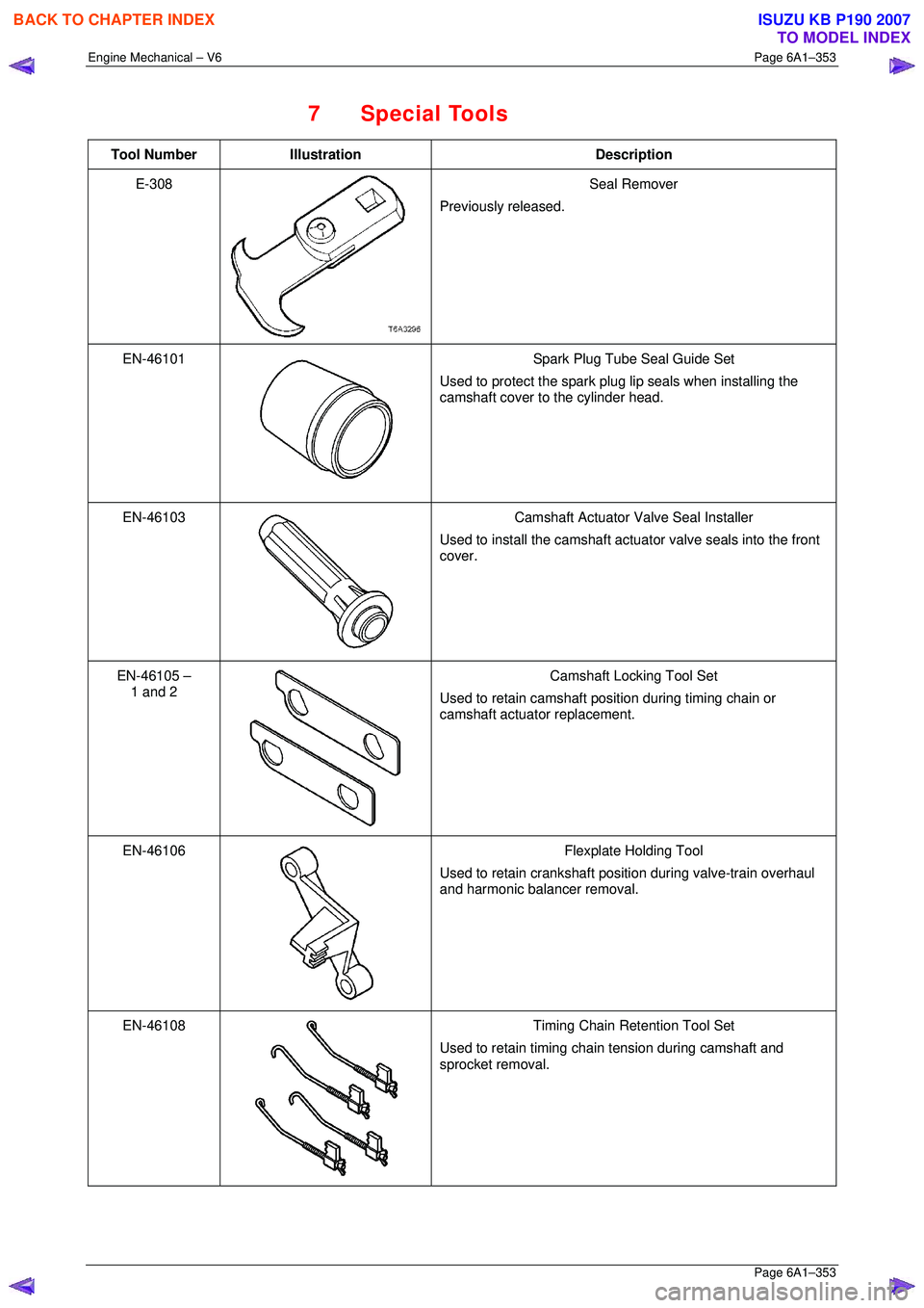
7 Special Tools
Tool Number Illustration Description
E-308
Seal Remover
Previously released.
EN-46101
Spark Plug Tube Seal Guide Set
Used to protect the spark plug lip seals when installing the
camshaft cover to the cylinder head.
EN-46103
Camshaft Actuator Valve Seal Installer
Used to install the camshaft actuat or valve seals into the front
cover.
EN-46105 – 1 and 2
Camshaft Locking Tool Set
Used to retain camshaft position during timing chain or
camshaft actuator replacement.
EN-46106
Flexplate Holding Tool
Used to retain crankshaft position during valve-train overhaul
and harmonic balancer removal.
EN-46108
Timing Chain Retention Tool Set
Used to retain timing chain tension during camshaft and
sprocket removal.
BACK TO CHAPTER INDEX
TO MODEL INDEX
ISUZU KB P190 2007
Page 3131 of 6020
Engine Mechanical – V6 Page 6A1–354
Page 6A1–354
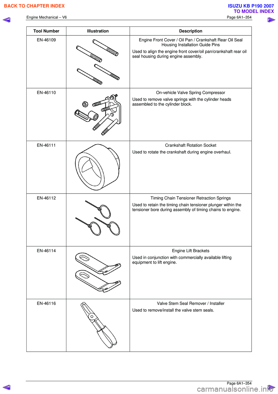
Tool Number Illustration Description
EN-46109
Engine Front Cover / Oil Pan / Crankshaft Rear Oil Seal
Housing Installation Guide Pins
Used to align the engine front co ver/oil pan/crankshaft rear oil
seal housing during engine assembly.
EN-46110
On-vehicle Valve Spring Compressor
Used to remove valve springs with the cylinder heads
assembled to the cylinder block.
EN-46111
Crankshaft Rotation Socket
Used to rotate the crankshaft during engine overhaul.
EN-46112
Timing Chain Tensioner Retraction Springs
Used to retain the timing chain tensioner plunger within the
tensioner bore during assembly of timing chains to engine.
EN-46114
Engine Lift Brackets
Used in conjunction with commercially available lifting
equipment to lift engine.
EN-46116
Valve Stem Seal Remover / Installer
Used to remove/install the valve stem seals.
BACK TO CHAPTER INDEX
TO MODEL INDEX
ISUZU KB P190 2007
Page 3133 of 6020
Engine Mechanical – V6 Page 6A1–356
Page 6A1–356
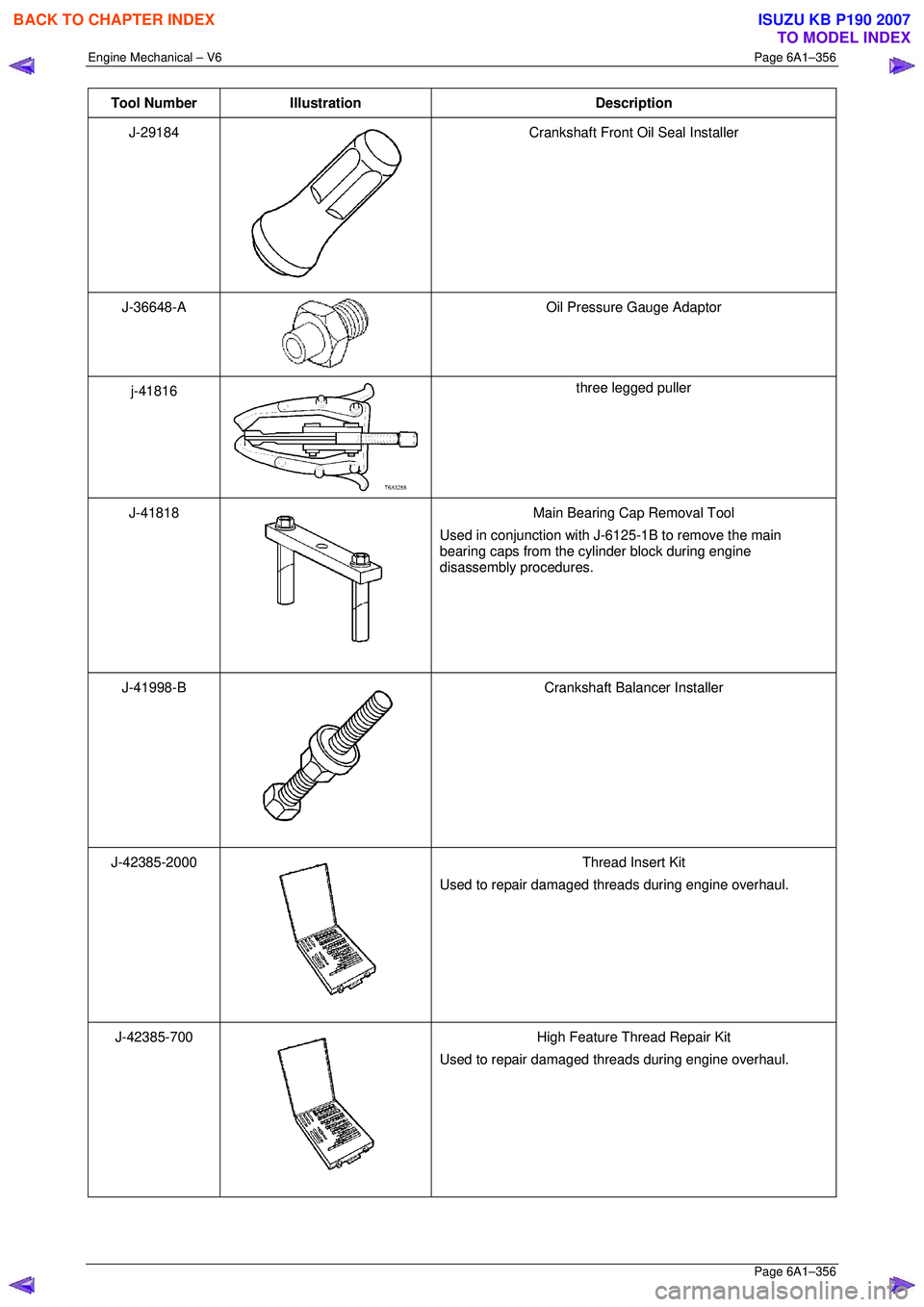
Tool Number Illustration Description
J-29184
Crankshaft Front Oil Seal Installer
J-36648-A
Oil Pressure Gauge Adaptor
j-41816
three legged puller
J-41818
Main Bearing Cap Removal Tool
Used in conjunction with J-6125-1B to remove the main
bearing caps from the cylinder block during engine
disassembly procedures.
J-41998-B
Crankshaft Balancer Installer
J-42385-2000
Thread Insert Kit
Used to repair damaged threads during engine overhaul.
J-42385-700
High Feature Thread Repair Kit
Used to repair damaged threads during engine overhaul.
BACK TO CHAPTER INDEX
TO MODEL INDEX
ISUZU KB P190 2007
Page 3134 of 6020
Engine Mechanical – V6 Page 6A1–357
Page 6A1–357
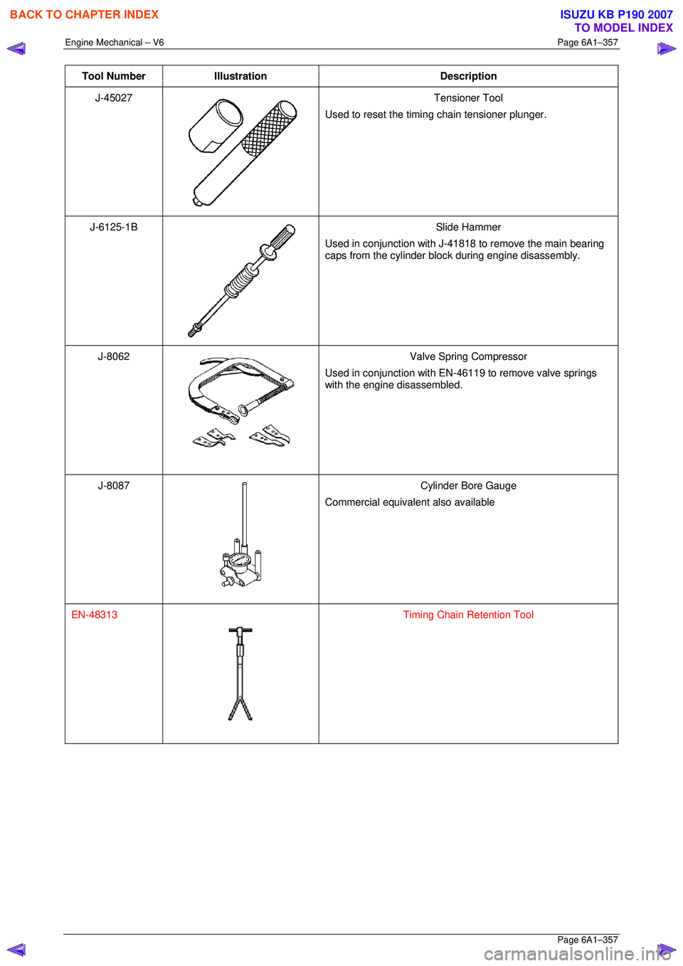
Tool Number Illustration Description
J-45027
Tensioner Tool
Used to reset the timing chain tensioner plunger.
J-6125-1B
Slide Hammer
Used in conjunction with J-41818 to remove the main bearing
caps from the cylinder block during engine disassembly.
J-8062
Valve Spring Compressor
Used in conjunction with EN-46119 to remove valve springs
with the engine disassembled.
J-8087
Cylinder Bore Gauge
Commercial equivalent also available
EN-48313
Timing Chain Retention Tool
BACK TO CHAPTER INDEX
TO MODEL INDEX
ISUZU KB P190 2007
Page 3137 of 6020

Engine Cooling – V6 Engine Page 6B1–2
Cooling System Pressure Testing ................................................................................................ ...................... 32
3.8 Thermostat ........................................................................................................................................................... 34
Remove ................................................................................................................................................................. 34
Test ....................................................................................................................................................................... 37
Dismantle ...................................................................................................................... ........................................ 37
Reassembly .......................................................................................................................................................... 37
Install .................................................................................................................................................................... 38
3.9 Coolant Recovery Reservoir ..................................................................................................... .......................... 39
Remove ................................................................................................................................................................. 39
Inspect .................................................................................................................................................................. 39
Install .................................................................................................................................................................... 39
3.10 Coolant Pump................................................................................................................... .................................... 40
Remove ................................................................................................................................................................. 40
Inspect .................................................................................................................................................................. 43
Reinstall ................................................................................................................................................................ 43
3.11 Coolant Outlet Housing ......................................................................................................... .............................. 45
Remove ................................................................................................................................................................. 45
Reinstall ................................................................................................................................................................ 46
3.12 Coolant Inlet Pipe............................................................................................................. .................................... 46
Remove ................................................................................................................................................................. 46
Install .................................................................................................................................................................... 48
3.13 Cooling Fan and Shroud Assembly ................................................................................................ ................... 48
Remove ................................................................................................................................................................. 48
Install .................................................................................................................................................................... 50
Disassemble ......................................................................................................................................................... 51
Reassemble .......................................................................................................................................................... 51
3.14 Flexible Transmission Cooler Hose .............................................................................................. ..................... 51
Replace ................................................................................................................................................................. 51
Reinstall ................................................................................................................................................................ 53
3.15 Radiator ....................................................................................................................... ......................................... 54
Remove ......................................................................................................................... ........................................ 54
Reinstall ................................................................................................................................................................ 56
Radiator Repair Procedure...................................................................................................... ............................ 57
Repairable Leaks ............................................................................................................................................. 57
Repair Method.................................................................................................................................................. 58
Tube Blocking................................................................................................................................................... 58
Header Repair .................................................................................................................. ................................ 58
General Core Repair ............................................................................................................ ............................ 59
Transmission Oil Cooler Leak Test .............................................................................................. .................... 60
Transmission Oil Cooler Seal Replacement. ...................................................................................... .............. 60
4 Engine Cooling System Diagnosis .....................................................................................................61
4.1 Poor Heater Operation......................................................................................................................................... 61
4.2 Leaking Cylinder Head Gasket ................................................................................................... ........................ 61
4.3 Question the Customer ....................................................................................................................................... 61
4.4 Diagnostic Chart .................................................................................................................................................. 61
4.5 Problems Not Requiring Disassembly of Cooling System ........................................................................... .... 63
4.6 Problems Requiring Disassembly of Cooling System ...................................................................................... 63
4.7 Black Light and Dye Leak Diagnosis Method .................................................................................................... 63
5 Specifications .......................................................................................................................................64
6 Torque Wrench Specifications................................................................................................... .........66
7 Special Tools ........................................................................................................................................67
BACK TO CHAPTER INDEX
TO MODEL INDEX
ISUZU KB P190 2007
Page 3140 of 6020
Engine Cooling – V6 Engine Page 6B1–5
2 General Description
2.1 Radiator Assembly
The radiator has an aluminium core and is of the cross-flow design. Plastic side tanks are attached to the core by clinch
tabs. The clinch tabs are formed as part of the core assembly.
The lower frame of the radiator assembly is attached to the vehicle frame by two bolts supported in rubber mounts, pegs
are attached to the upper area of each side tank. These pegs are used to support the radiator with two rubber insert
mounting brackets.
A high temperature rubber seal is used to seal the mating surface between the core and each side tank. The seal(s)
must be replaced any time the side tank is removed from the core.
NOTE
The radiator core side tanks or transmission oil
cooler cannot be replaced separately. If there is a
fault with any of these components, the radiator
assembly must be replaced. Small core repairs
may be made using an aluminised silicon based
liquid repair agent. Refer to 3.15 Radiator in
this Section.
For vehicles with automatic transmission, a transmission oil cooler is located in the right-hand side radiator tank. The
cooler pipes from and to the transmission are connected to the oil cooler flexible hoses by means of quick connect
fittings.
The cooling fan motor is attached by three screws to the one-piece plastic fan shroud. In turn, the fan shroud is mounted
to the rear of the radiator and is located and supported by two bolts and two locating tabs. The upper clips lock the fan
shroud in place and can be released by hand to facilitate fan shroud removal. The shroud must be removed to allow fan
motor and blade assembly removal.
One harness connector is mounted to the upper section of the fan shroud allowing the fan motor and blade assemblies
to be removed individually from the shroud. The fan motor and blade is balanced as an assembly. These two
components are serviced only as a unit and are not to be separated.
The shroud, fan assembly and transmission cooler hoses can be removed and installed individually from the vehicle. For
removal and installation procedures, refer to 3.13Cooling Fan and Shroud Assembly, 3.14 Flexible Transmission
Cooler Hose and 3.15 Radiator in this Section.
BACK TO CHAPTER INDEX
TO MODEL INDEX
ISUZU KB P190 2007
Page 3142 of 6020
Engine Cooling – V6 Engine Page 6B1–7
2.2 Cooling Fan – Standard Specification
Overview
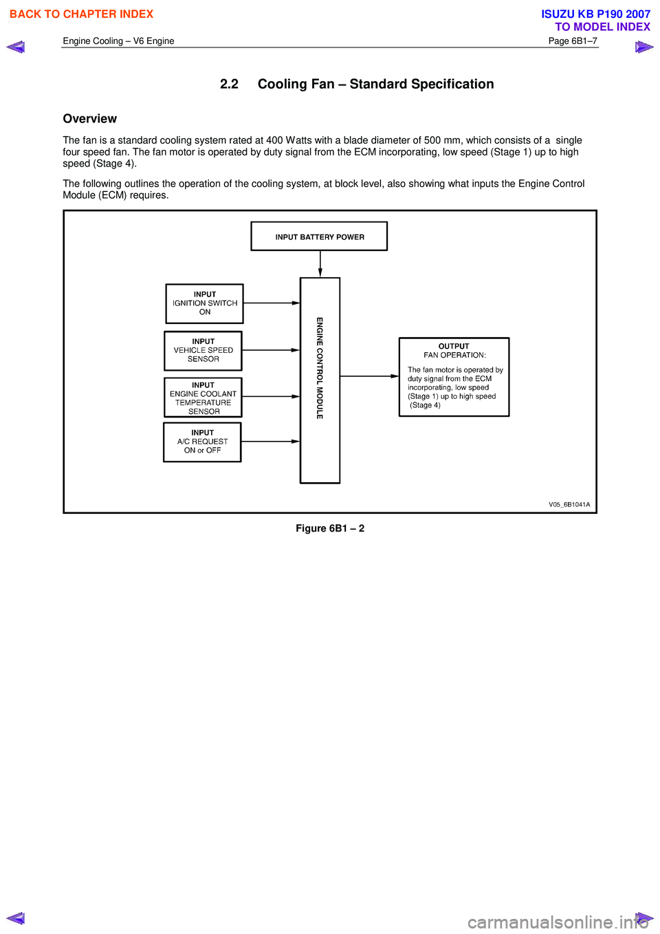
The fan is a standard cooling system rated at 400 W atts with a blade diameter of 500 mm, which consists of a single
four speed fan. The fan motor is operated by duty signal from the ECM incorporating, low speed (Stage 1) up to high
speed (Stage 4).
The following outlines the operation of the cooling system, at block level, also showing what inputs the Engine Control
Module (ECM) requires.
Figure 6B1 – 2
BACK TO CHAPTER INDEX
TO MODEL INDEX
ISUZU KB P190 2007
Page 3143 of 6020
Engine Cooling – V6 Engine Page 6B1–8
Cooling Fan and Shroud Assembly
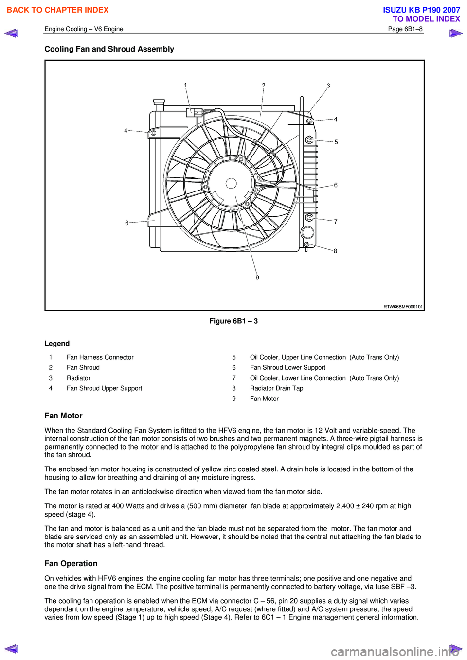
Figure 6B1 – 3
Legend
1 Fan Harness Connector
2 Fan Shroud
3 Radiator
4 Fan Shroud Upper Support 5 Oil Cooler, Upper Line Connection (Auto Trans Only)
6 Fan Shroud Lower Support
7 Oil Cooler, Lower Line Connection (Auto Trans Only)
8 Radiator Drain Tap
9 Fan Motor
Fan Motor
W hen the Standard Cooling Fan System is fitted to the HFV6 engine, the fan motor is 12 Volt and variable-speed. The
internal construction of the fan motor consists of two brushes and two permanent magnets. A three-wire pigtail harness is
permanently connected to the motor and is attached to the polypropylene fan shroud by integral clips moulded as part of
the fan shroud.
The enclosed fan motor housing is constructed of yellow zinc coated steel. A drain hole is located in the bottom of the
housing to allow for breathing and draining of any moisture ingress.
The fan motor rotates in an anticlockwise direction when viewed from the fan motor side.
The motor is rated at 400 W atts and drives a (500 mm) diameter fan blade at approximately 2,400 ± 240 rpm at high
speed (stage 4).
The fan and motor is balanced as a unit and the fan blade must not be separated from the motor. The fan motor and
blade are serviced only as an assembled unit. However, it should be noted that the central nut attaching the fan blade to
the motor shaft has a left-hand thread.
Fan Operation
On vehicles with HFV6 engines, the engine cooling fan motor has three terminals; one positive and one negative and
one the drive signal from the ECM. The positive terminal is permanently connected to battery voltage, via fuse SBF –3.
The cooling fan operation is enabled when the ECM via connector C – 56, pin 20 supplies a duty signal which varies
dependant on the engine temperature, vehicle speed, A/C request (where fitted) and A/C system pressure, the speed
varies from low speed (Stage 1) up to high speed (Stage 4). Refer to 6C1 – 1 Engine management general information.
BACK TO CHAPTER INDEX
TO MODEL INDEX
ISUZU KB P190 2007
Page 3147 of 6020
Engine Cooling – V6 Engine Page 6B1–12
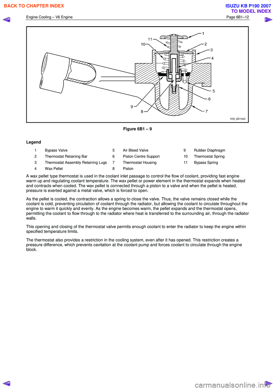
Figure 6B1 – 9
Legend
1 Bypass Valve
2 Thermostat Retaining Bar
3 Thermostat Assembly Retaining Lugs
4 Wax Pellet 5 Air Bleed Valve
6 Piston Centre Support
7 Thermostat Housing
8 Piston 9 Rubber Diaphragm
10 Thermostat Spring
11 Bypass Spring
A wax pellet type thermostat is used in the coolant inlet passage to control the flow of coolant, providing fast engine
warm up and regulating coolant temperature. The wax pellet or power element in the thermostat expands when heated
and contracts when cooled. The wax pellet is connected through a piston to a valve and when the pellet is heated,
pressure is exerted against a metal valve, which is forced to open.
As the pellet is cooled, the contraction allows a spring to close the valve. Thus, the valve remains closed while the
coolant is cold, preventing circulation of coolant through the radiator, but allowing the coolant to circulate throughout the
engine to warm it quickly and evenly. As the engine becomes warm, the pellet expands and the thermostat opens,
permitting the coolant to flow through to the radiator where heat is transferred to the surrounding air, through the radiator
walls.
This opening and closing of the thermostat valve permits enough coolant to enter the radiator to keep the engine within
specified temperature limits.
The thermostat also provides a restriction in the cooling system, even after it has opened. This restriction creates a
pressure difference, which prevents cavitation at the coolant pump and forces coolant to circulate through the engine
block.
BACK TO CHAPTER INDEX
TO MODEL INDEX
ISUZU KB P190 2007
Page 3151 of 6020
Engine Cooling – V6 Engine Page 6B1–16
3 Service Operations
3.1 Service Notes
Safety
• To avoid serious personal injury, never
remove the coolant filler pressure cap on
the coolant outlet housing when the
engine is hot, even if the cooling system
should require filling. Sudden release of
cooling system pressure is very
dangerous.
• The vehicle is fitted with an electric
radiator cooling fan. When working around
the engine compartment, keep clear of the
fan as it may start without warning.
Before removing the coolant filler cap, allow the engine to cool, then place a shop rag over the coolant filler cap and then
slowly turn the cap anticlockwise, approximately 1½ turns, until the pressure relief position is reached. The pressure
relief position will allow any remaining pressure within the system to escape into the coolant recovery reservoir. Continue
to rotate the cap anticlockwise until the cap can be safely removed.
Periodic Servicing
The cooling system requires little attention except for maintaining the coolant to the correct level in the recovery reservoir
and periodic servicing at the time or distance intervals as outlined in 0B Lubrication and Service.
Periodic servicing includes:
1 Checking coolant level. Refer to 3.3 Draining and Filling Cooling System in this Section.
2 Checking coolant concentration. Refer to 3.2 Coolant Maintenance – Testing Coolant Concentration in this Section.
3 Pressure test cooling system and coolant filler cap. Refer to 3.7 Pressure Testing in this Section.
4 Tighten hose clamps and inspect all hoses. Refer to 3.6 Coolant Hoses in this Section. Replace hoses if swollen or deteriorated.
Always wear protective safety glasses when
working with spring type hose clamps. Failure
to do so could result in eye injury.
5 Clean out cooling system, refer to 3.4 Cleaning Cooling System – Cooling System Flush, in this Section and refill. Refer to 3.3 Draining and Filling Cooling System in this Section.
Environmental Issues
To reduce environmental impact and maintenance cost, whenever the coolant is drained from any engine, the service
records are to be checked to determine when the coolant was last changed. If more than six months life is left before the
next coolant change, then the following procedure is to be followed:
1 W hen draining the coolant from the engine, use a clean container to hold at least 12 litres of coolant and ensure that the coolant is not contaminated in the draining process.
2 After repairs have been completed, refill the engine cooling system with the drained coolant.
BACK TO CHAPTER INDEX
TO MODEL INDEX
ISUZU KB P190 2007