lock ISUZU KB P190 2007 Workshop Repair Manual
[x] Cancel search | Manufacturer: ISUZU, Model Year: 2007, Model line: KB P190, Model: ISUZU KB P190 2007Pages: 6020, PDF Size: 70.23 MB
Page 3919 of 6020
Automatic Transmission – 4L60E – On-vehicle Servicing Page 7C4–6
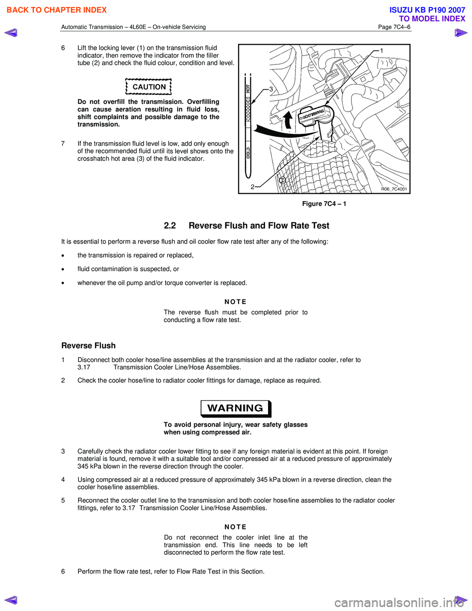
6 Lift the locking lever (1) on the transmission fluid
indicator, then remove the indicator from the filler
tube (2) and check the fluid colour, condition and level.
Do not overfill the transmission. Overfilling
can cause aeration resulting in fluid loss,
shift complaints and possible damage to the
transmission.
7 If the transmission fluid level is low, add only enough of the recommended fluid until
its level shows onto the
crosshatch hot area (3) of the fluid indicator.
Figure 7C4 – 1
2.2 Reverse Flush and Flow Rate Test
It is essential to perform a reverse flush and oil cooler flow rate test after any of the following:
• the transmission is repaired or replaced,
• fluid contamination is suspected, or
• whenever the oil pump and/or torque converter is replaced.
NOTE
The reverse flush must be completed prior to
conducting a flow rate test.
Reverse Flush
1 Disconnect both cooler hose/line assemblies at the transmission and at the radiator cooler, refer to 3.17 Transmission Cooler Line/Hose Assemblies.
2 Check the cooler hose/line to radiator cooler fittings for damage, replace as required.
To avoid personal injury, wear safety glasses
when using compressed air.
3 Carefully check the radiator cooler lower fitting to see if any foreign material is evident at this point. If foreign material is found, remove it with a suitable tool and/or compressed air at a reduced pressure of approximately
345 kPa blown in the reverse direction through the cooler.
4 Using compressed air at a reduced pressure of approximately 345 kPa blown in a reverse direction, clean the cooler hose/line assemblies.
5 Reconnect the cooler outlet line to the transmission and both cooler hose/line assemblies to the radiator cooler fittings, refer to 3.17 Transmission Cooler Line/Hose Assemblies.
NOTE
Do not reconnect the cooler inlet line at the
transmission end. This line needs to be left
disconnected to perform the flow rate test.
6 Perform the flow rate test, refer to Flow Rate Test in this Section.
BACK TO CHAPTER INDEX
TO MODEL INDEX
ISUZU KB P190 2007
Page 3925 of 6020
Automatic Transmission – 4L60E – On-vehicle Servicing Page 7C4–12
4 Remove the knob together with the button (5) and spring (6) from the selector lever assembly (7).
5 Turn the sleeve (8) counter clockwise to remove it, make note of the number of turns required to free it.
6 Remove the harness connectors from the base plate (9).
7 Remove the upper housing (10) which is held in place by four latched fasteners.
8 Remove the attaching screw (11) and spring plate (12).
9 Remove the grooved pin (13).
10 Using a small flat blade screwdriver, gently prise the upper end of the selector cable (14) from the pin on the selector lever linkage (15).
11 Remove the selector lever assembly by pressing the rod down (lever in the N position).
12 If required, remove the lamp (16) from its socket by aligning the groove in the socket and the protruding part of the lamp.
13 If required, remove the nut (17), four places, and the shift selector base plate.
Reinstall
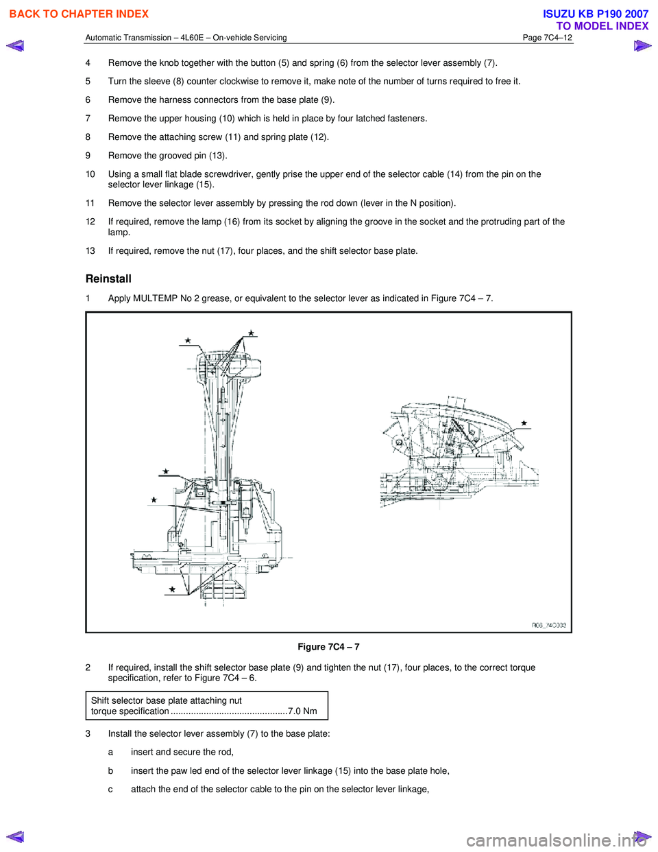
1 Apply MULTEMP No 2 grease, or equivalent to the selector lever as indicated in Figure 7C4 – 7.
Figure 7C4 – 7
2 If required, install the shift selector base plate (9) and tighten the nut (17), four places, to the correct torque specification, refer to Figure 7C4 – 6.
Shift selector base plate attaching nut
torque specification ..............................................7.0 Nm
3 Install the selector lever assembly (7) to the base plate: a insert and secure the rod,
b insert the paw led end of the selector lever linkage (15) into the base plate hole,
c attach the end of the selector cable to the pin on the selector lever linkage,
BACK TO CHAPTER INDEX
TO MODEL INDEX
ISUZU KB P190 2007
Page 3926 of 6020
Automatic Transmission – 4L60E – On-vehicle Servicing Page 7C4–13
d Install the grooved pin (13) in the selector lever.
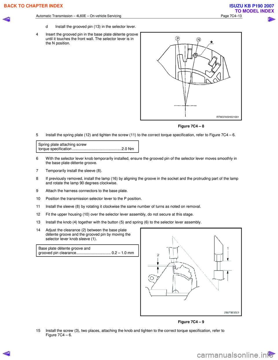
4 Insert the grooved pin in the base plate détente groove until it touches the front wall. The selector lever is in
the N position.
Figure 7C4 – 8
5 Install the spring plate (12) and tighten the screw (11) to the correct torque specification, refer to Figure 7C4 – 6.
Spring plate attaching screw
torque specification ..............................................2.0 Nm
6 W ith the selector lever knob temporarily installed, ensure the grooved pin of the selector lever moves smoothly in the base plate détente groove.
7 Temporarily install the sleeve (8).
8 If previously removed, install the lamp (16) by aligning the groove in the socket and the protruding part of the lamp and rotate the lamp 90 degrees clockwise.
9 Attach the harness connectors to the base plate.
10 Position the transmission selector lever to the P position.
11 Install the sleeve (8) by rotating it clockwise the same number of turns as noted on removal.
12 Fit the upper housing (10) over the selector lever assembly, do not secure at this stage.
13 Install the knob (4) together with the button (5) and spring (6) to the selector lever assembly.
14 Adjust the clearance (2) between the base plate détente groove and the grooved pin by moving the
selector lever knob sleeve (1).
Base plate détente groove and
grooved pin clearance................................ 0.2 – 1.0 mm
Figure 7C4 – 9
15 Install the screw (3), two places, attaching the knob and tighten to the correct torque specification, refer to Figure 7C4 – 6.
BACK TO CHAPTER INDEX
TO MODEL INDEX
ISUZU KB P190 2007
Page 3929 of 6020

Automatic Transmission – 4L60E – On-vehicle Servicing Page 7C4–16
8 Slide the cover (3) in the direction shown by the
arrow (1).
9 Using a small flat blade screwdriver, move the lock piece (4) from the position indicated by the arrow (2).
Continue to move the lock piece until the adjuster (5)
position begins to change.
Figure 7C4 – 12
10 Connect the selector cable to the transmission external manual shaft linkage.
11 Insert the lock piece in the adjuster to engage with the serrated cable end (cable length adjustment).
12 Slide the cover (1) on the adjuster and secure the lock piece.
Figure 7C4 – 13
13 Install the heat shield (7) and tighten the attaching screws (1 and 6) to the correct torque specification, refer to Figure 7C4 – 10.
Heat shield front attaching screw
torque specification ............................................ 25.0 Nm
Heat shield rear attaching screw torque specification ..............................................9.0 Nm
14 Move the selector lever to the P position and press the selector lever knob button five times.
15 Ensure the selector lever moves smoothly to each of its positions.
16 Check if the shift position indicated by the selector lever and the actual shift position are the same, rectify if required.
17 Lower the vehicle to the ground. Ensure the engine can only be started with the transmission selector lever in Park or Neutral position and the back-up lamps work correctly. If required, adjust the neutral start and back-up lamp
switch, refer to 3.4 Neutral Start and Back-up Lamp Switch.
18 Ensure the gear selection operates correctly.
19 Install the front and rear console, refer to 10 Cab.
3.4 Neutral Start and Back-up Lamp Switch
Remove
1 Position the transmission selector lever to the P position.
2 Raise the vehicle and support in a safe manner, refer to 0A General Information for the location of support points.
BACK TO CHAPTER INDEX
TO MODEL INDEX
ISUZU KB P190 2007
Page 3932 of 6020

Automatic Transmission – 4L60E – On-vehicle Servicing Page 7C4–19
Reinstall
1 Lubricate a new O-ring seal with petroleum jelly and install it to the vehicle speed sensor.
2 Install the speed sensor to the transmission extension housing.
3 Install the attaching bolt and tighten to the correct torque specification.
Vehicle speed sensor attaching bolt
torque specification ............................................ 12.0 Nm
4 Connect the connector to the speed sensor.
5 Lower the vehicle to the ground.
3.6 Manual Shaft Oil Seal
Replace
NOTE
This procedure requires the use of special tool
No. AU583.
1 Raise the vehicle and support in a safe manner, refer to 0A General Information for the location of support points.
2 Remove the neutral start and back-up lamp switch, refer to 3.4 Neutral Start and Back-up Lamp Switch.
3 Assemble the seal remover, Tool No. AU583-3 (1) by installing the remover nut, Tool No. AU583-4 (2) with
its threaded inner diameter closest to the hexagonal
head of the seal remover tool. Install the nut up to the
hexagonal head.
4 Install the assembled seal remover tool over the manual shaft (3) engaging the tapered thread end (4)
into the seal.
Do not over tighten the seal remover tool in
the seal.
5 Rotate the hexagonal head of the seal remover tool clockwise, until the thread grips the steel shell of the
seal.
Figure 7C4 – 16
6 W hile holding the hexagonal head of the seal remover tool (1) rotate the remover nut (2) clockwise, until it
contacts the transmission case.
7 Continue rotating the remover nut until the seal is pulled into the remover nut cavity.
8 Remove and discard the seal.
Figure 7C4 – 17
BACK TO CHAPTER INDEX
TO MODEL INDEX
ISUZU KB P190 2007
Page 3952 of 6020
Automatic Transmission – 4L60E – On-vehicle Servicing Page 7C4–39
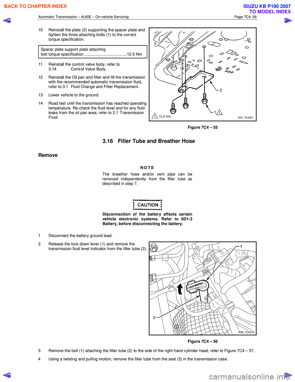
10 Reinstall the plate (2) supporting the spacer plate and
tighten the three attaching bolts (1) to the correct
torque specification.
Spacer plate support plate attaching
bolt torque specification ..................................... 12.0 Nm
11 Reinstall the control valve body, refer to 3.14 Control Valve Body.
12 Reinstall the Oil pan and filter and fill the transmission with the recommended automatic transmission fluid,
refer to 3.1 Fluid Change and Filter Replacement.
13 Lower vehicle to the ground.
14 Road test until the transmission has reached operating temperature. Re-check the fluid level and for any fluid
leaks from the oil pan area, refer to 2.1 Transmission
Fluid.
Figure 7C4 – 55
3.16 Filler Tube and Breather Hose
Remove
NOTE
The breather hose and/or vent pipe can be
removed independently from the filler tube as
described in step 7.
Disconnection of the battery affects certain
vehicle electronic systems. Refer to 6D1-3
Battery, before disconnecting the battery.
1 Disconnect the battery ground lead.
2 Release the lock down lever (1) and remove the transmission fluid level indicator from the filler tube (2).
Figure 7C4 – 56
3 Remove the bolt (1) attaching the filler tube (2) to the side of the right-hand cylinder head, refer to Figure 7C4 – 57.
4 Using a twisting and pulling motion, remove the filler tube from the seal (3) in the transmission case.
BACK TO CHAPTER INDEX
TO MODEL INDEX
ISUZU KB P190 2007
Page 3954 of 6020
Automatic Transmission – 4L60E – On-vehicle Servicing Page 7C4–41
3.17 Transmission Cooler Line/Hose
Assemblies
Remove
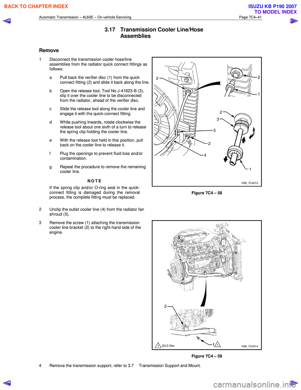
1 Disconnect the transmission cooler hose/line assemblies from the radiator quick connect fittings as
follows:
a Pull back the verifier disc (1) from the quick connect fitting (2) and slide it back along the line.
b Open the release tool, Tool No J-41623-B (3), slip it over the cooler line to be disconnected
from the radiator, ahead of the verifier disc.
c Slide the release tool along the cooler line and engage it with the quick-connect fitting.
d W hile pushing inwards, rotate clockwise the release tool about one sixth of a turn to release
the spring clip holding the cooler line.
e With the release tool held in this position, pull back on the cooler line to release it.
f Plug the openings to prevent fluid loss and/or contamination.
g Repeat the procedure to remove the remaining cooler line.
NOTE
If the spring clip and/or O-ring seal in the quick-
connect fitting is damaged during the removal
process, the complete fitting must be replaced.
2 Unclip the outlet cooler line (4) from the radiator fan shroud (5).
Figure 7C4 – 58
3 Remove the screw (1) attaching the transmission cooler line bracket (2) to the right-hand side of the
engine.
Figure 7C4 – 59
4 Remove the transmission support, refer to 3.7 Transmission Support and Mount.
BACK TO CHAPTER INDEX
TO MODEL INDEX
ISUZU KB P190 2007
Page 3955 of 6020

Automatic Transmission – 4L60E – On-vehicle Servicing Page 7C4–42
5 Carefully lower the rear of the transmission sufficiently to get access to the cooler lines.
6 Place a suitable sized drip tray underneath the transmission.
7 W ith the rear of the transmission lowered, disconnect the cooler lines from the transmission, as follows:
a Pull back the verifier disc (1) to release it and slide it back along the cooler line (2).
b Open the release tool, Tool No J-41623-B (3), slip it over the cooler line to be disconnected
from the transmission, ahead of the verifier disc.
c Slide the release tool along the cooler line and engage it with the quick-connect fitting (4).
d W hile pushing inwards, rotate clockwise the release tool about one sixth of a turn to release
the spring clip holding the cooler line.
e With the release tool held in this position, pull back on the cooler line to release it.
f Plug all openings to prevent fluid loss and/or contamination.
g Repeat this process with the remaining cooler line.
NOTE
If the spring clip and/or O-ring seal in the quick-
connect fitting is damaged during the removal
process, the complete fitting must be replaced.
Figure 7C4 – 60
8 Carefully remove the two cooler lines from the vehicle.
9 As required, separate the two cooler lines by removing the bracket and the two clips.
Reinstall
1 On the transmission end, ensure the spring clip and/or O-ring seal in each quick-connect fitting is not damaged, replace the complete fitting if required.
2 If required, fit the bracket and the two clips to attach the transmission two cooler lines together.
3 Position the cooler lines in place, attach the cooler line bracket (2) with the screw (1) hand tight to the right-hand side of the engine, refer to Figure 7C4 – 59.
4 Remove the plugs from the cooler lines and transmission fittings and wipe all exposed parts clean.
5 At the transmission end, smear the fluid lines rear fittings with clean automatic transmission fluid and push the quick-connect fittings together.
If the verifier disc does not clip into place, the
quick-connect fitting is not engaged, rectify
as required.
6 As a security check, push and clip each verification disc into place over the quick-connect fittings. If difficulty is experienced, repeat the installation process until the verification disc can be clipped into place over the
transmission quick-connect fitting.
7 Reinstall the transmission support, refer to 3.7 Transmission Support and Mount.
8 Remove the plugs from the cooler lines and radiator fittings and wipe all exposed parts clean.
9 At the radiator end, smear the fluid lines fittings with clean automatic transmission fluid and push the quick-connect fittings together, refer to Figure 7C4 – 58.
BACK TO CHAPTER INDEX
TO MODEL INDEX
ISUZU KB P190 2007
Page 3960 of 6020
Automatic Transmission – 4L60E – On-vehicle Servicing Page 7C4–47
14 Reconnect the fuel and EVAP pipes three brackets and clips, refer to 6C Fuel System – V6.
15 Reinstall the following components:
a Starter motor, refer to 6D1-2 Starting System.
b Transmission support, refer to 3.7 Transmission Support and Mount.
c Front and centre exhaust assemblies, refer to 6F Exhaust System.
d Rear propeller shaft and for 4WD front propeller shaft, refer to 4A Propeller Shaft.
16 Reconnect the harness connectors to the following: a Vehicle speed sensor, refer to 3.5 Vehicle Speed Sensor.
b Neutral start and back-up switch, refer to 3.4 Neutral Start and Back-up Lamp Switch.
c For the following on 4W D vehicles, refer to 7D Transfer Case and Adaptor Housing:
• neutral switch,
• 2WD – 4WD shift actuator switch,
• speed sensor.
17 Reinstall the selector cable to the transmission external manual shaft linkage, secure the selector cable to the bracket and attach the heat shield to the neutral start and back-up lamp switch, refer to 3.3 Selector Cable
Assembly.
18 Perform a reverse flush of the cooler lines and a flow rate test, refer to 2.2 Reverse Flush and Flow Rate, if either of the following applies:
• the transmission fluid is contaminated,
• the transmission has been replaced,
• the torque converter has been replaced, or
• the transmission oil pump has been replaced.
19 Lower the vehicle to the ground.
20 If required, top up the transmission fluid level (cold).
21 Reconnect the battery ground lead.
22 Start the engine and check for any fluid leaking at the fittings. If a leak is found, stop the engine and rectify the leak.
23 Road test until the transmission has reached operating temperature. Re-check the fluid level and for any fluid leaks, refer to 2.1 Transmission Fluid.
3.19 Transmission Control Module
Remove
1 Ensure the ignition switch is in the OFF position.
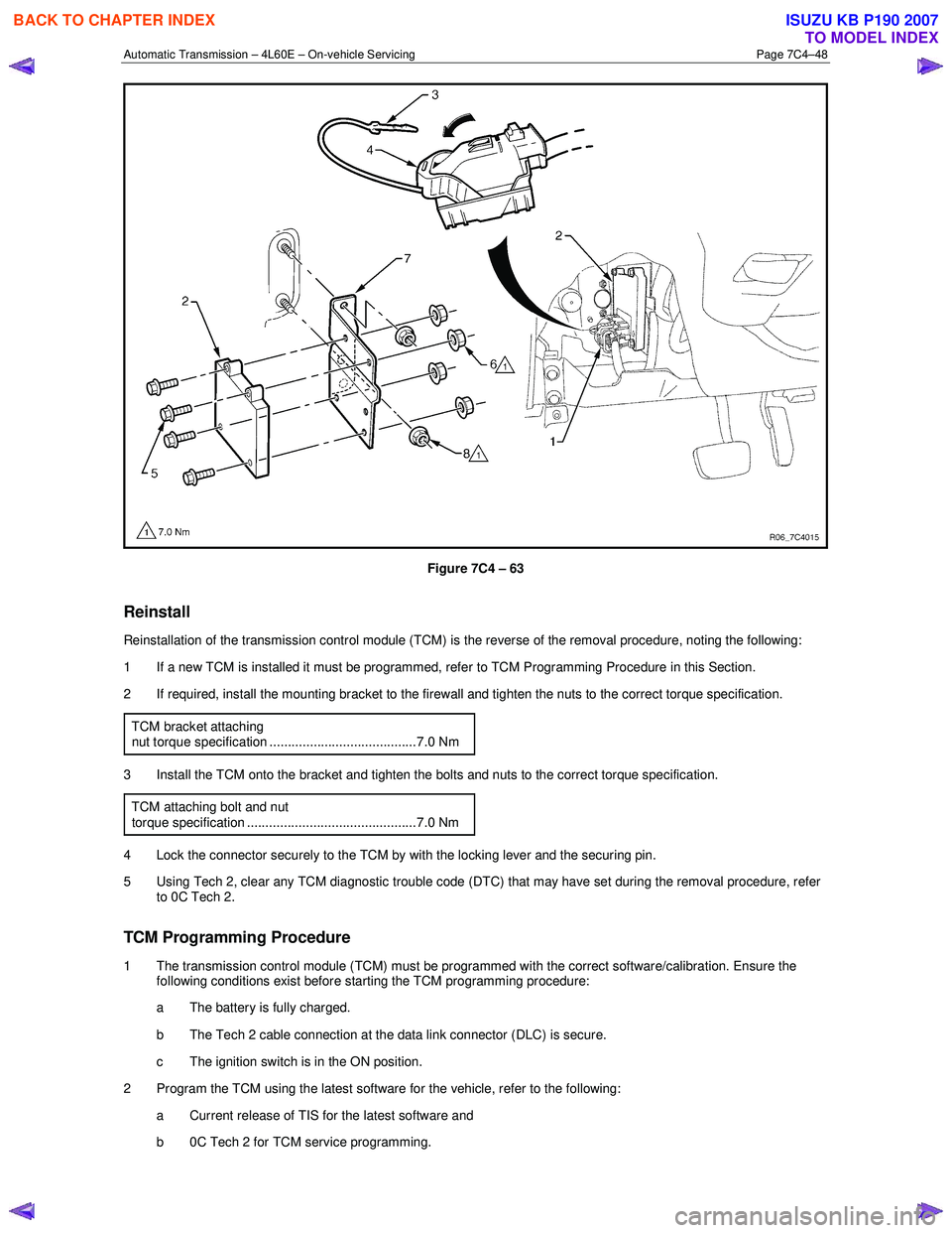
2 Disconnect the connector (1) from the transmission control module (TCM) (2) as follows, refer to Figure 7C4 – 63: a remove the securing pin (3),
b press the locking tab and swing the lever (4) to free the connector,
c remove the connector.
3 Remove the four bolts (5) and nuts (6), then the TCM from the mounting bracket (7).
4 If required, remove the two nuts (8) and the mounting bracket from the firewall.
BACK TO CHAPTER INDEX
TO MODEL INDEX
ISUZU KB P190 2007
Page 3961 of 6020
Automatic Transmission – 4L60E – On-vehicle Servicing Page 7C4–48
Figure 7C4 – 63
Reinstall
Reinstallation of the transmission control module (TCM) is the reverse of the removal procedure, noting the following:
1 If a new TCM is installed it must be programmed, refer to TCM Programming Procedure in this Section.
2 If required, install the mounting bracket to the firewall and tighten the nuts to the correct torque specification.
TCM bracket attaching
nut torque specification ........................................7.0 Nm
3 Install the TCM onto the bracket and tighten the bolts and nuts to the correct torque specification. TCM attaching bolt and nut
torque specification ..............................................7.0 Nm
4 Lock the connector securely to the TCM by with the locking lever and the securing pin.
5 Using Tech 2, clear any TCM diagnostic trouble code (DTC) that may have set during the removal procedure, refer to 0C Tech 2.
TCM Programming Procedure
1 The transmission control module (TCM) must be programmed with the correct software/calibration. Ensure the following conditions exist before starting the TCM programming procedure:
a The battery is fully charged.
b The Tech 2 cable connection at the data link connector (DLC) is secure.
c The ignition switch is in the ON position.
2 Program the TCM using the latest software for the vehicle, refer to the following: a Current release of TIS for the latest software and
b 0C Tech 2 for TCM service programming.
BACK TO CHAPTER INDEX
TO MODEL INDEX
ISUZU KB P190 2007