lock ISUZU KB P190 2007 Workshop Repair Manual
[x] Cancel search | Manufacturer: ISUZU, Model Year: 2007, Model line: KB P190, Model: ISUZU KB P190 2007Pages: 6020, PDF Size: 70.23 MB
Page 4033 of 6020

TRANSMISSION CONTROL SYSTEM (AW30–40LE) 7A2-67
DTC P0742 (Flash Code 53)
RTW 77ALF001501
Circuit Description
The lock-up solenoid SL of the torque converter clutch
(TCC) controls the lock-up clutch by a signal according
to the lock-up position judgment of the Transmission
Control Module (TCM) when the vehicle runs.
This function can improve the fuel consumption to
almost the same extent as the manual transmission.
The lock-up solenoid SL is put into B+ by the TCM, so
that the solenoid is actuated with the result of lock-up.
Condition For Running The DTC
All of the following conditions are met.
(1)
All of the following conditions are met for 2
seconds or more continuously.
• The supply voltage is more than 10.2 volts and less than 15.5 volts.
• DTC U2104 is not detecting failure or not deciding failure.
• DTC U2105 is not detecting failure or not deciding failure.
• Engine revolution signal is not detecting failure or not deciding failure.
• The engine revolution is more than 550rpm.
BACK TO CHAPTER INDEX
TO MODEL INDEX
ISUZU KB P190 2007
Page 4034 of 6020

7A2-68 TRANSMISSION CONTROL SYSTEM (AW30–40LE)
(2) Oil temperature is more than 20 °C (68 °F), and
water temperature signal is more than 70 °C
(158 °F).
(3) 20 seconds or more passed after D position is detected.
(4) Oil temperature sensor is not deciding failure.
(5) Engine coolant temperature sensor is not detecting failure or not deciding failure.
(6) The engine revolution is more than 600 rpm.
(7) Engine revolution sensor is not detecting failure o
r
not deciding failure.
(8) T/F condition is high.
(9) T/F Hi-Low SW is not detecting failure or not deciding failure.
(10) Output revolution sensor is not detecting failure o
r
not deciding failure.
(11) S1 solenoid is not detecting failure or not deciding
failure. (Electronic failure)
(12) S2 solenoid is not detecting failure or not deciding
failure. (Electronic failure)
(13) L-up solenoid is not detecting failure or not
deciding failure. (Electronic failure)
(14) Selector position switch is not detecting failure o
r
not deciding failure.
(15) DTC U2104 is not detecting failure or not deciding
failure.
(16) DTC U2105 is not detecting failure or not deciding
failure.
(17) Input revolution sensor is not deciding failure.
(18) Throttle signal is not detecting failure or not
deciding failure.
(19) Not emergency mode.
(20) Engine torque signal is not detecting failure or not
deciding failure.
(21) Pressure control solenoid is not detecting failure
not deciding failure.
(22) All of the following conditions are met.
• Device Control is not operating.
• Disable Normal Communication Service is receiving enable.
• DTC Clear is not operating.
Condition For Setting The DTC
The following conditions are detected two times or more
between ignition “ON” and ignition “OFF”.
The TCM detects following conditions are met for 1
second continuously.
• 2 second passed after gear change output and L-up “ON”/”OFF” output.
• T/C revolution difference more than 100 rpm for 1 second continuously.
• 3rd gear lock-up “OFF”.
Action Taken When The DTC Sets
• No squat control. (For preventing engine stall)
• Fix 1st gear to prevent engine stall when vehicle speed is and below 10 km/h (6 mph). (Cancel at 15
km/h {9 mph})
• Check Trans “ON”.
• DTC stored.
• MIL request “ON”. (EURO 4 only)
Conditions For Clearing The DTC
• The DTC can be cleared from the TCM history by
using a scan tool.
• The DTC will be cleared from history when the vehicle has achieved 40 warm-up cycles without a
failure reported.
•
After more than 1 second has elapsed after the
ignition key has been turned “ON”, short between
No.11 and No.4 (ground) of DLC (Data Link
Connector). Then, after 1 second, but within 6
seconds, discontinue shorting.
Diagnostic Aids
• Inspect the wiring for poor electrical connection at the TCM. Look for possible bent, backed out, deformed
or damaged terminals. Check for weak terminal
tension as well. Also check for a chafed wire that
could short to bare metal or other wiring.
Inspect for a broken wire inside the insulation.
• W hen diagnosing for a possible intermittent short o
r
open condition, move the wiring harness while
observing test equipment for a change.
BACK TO CHAPTER INDEX
TO MODEL INDEX
ISUZU KB P190 2007
Page 4057 of 6020

TRANSMISSION CONTROL SYSTEM (AW30–40LE) 7A2-91
• Feedback current value is less than 92 mA
(2)
All of the following conditions are met for 0.5
seconds or more continuously. (DTC P0963)
• 1 second or more passed after open failure
detection condition is met or open failure is not
detected after ignition “ON”.
• Feedback current value is more than 1357 mA.
Action Taken When The DTC Sets
• No squat control.
• No line pressure reduction control at gear change.
• No lock-up control.
• No slope control.
• No torque reduction control.
• No line pressure reduction control at garage.
• Line pressure FULL output.
• No shift solenoid functional failure detection.
• No L-up solenoid functional failure detection.
• No pressure control solenoid Feedback stuck failure detection.
• Check Trans “ON”.
• DTC stored.
• MIL request “ON”. (EURO 4 only)
Conditions For Clearing The DTC
•
The DTC can be cleared from the TCM history by
using a scan tool.
• The DTC will be cleared from history when the vehicle has achieved 40 warm-up cycles without a
failure reported.
•
After more than 1 second has elapsed after the
ignition key has been turned “ON”, short between
No.11 and No.4 (ground) of DLC (Data Link
Connector). Then, after 1 second, but within 6
seconds, discontinue shorting.
Diagnostic Aids
• Inspect the wiring for poor electrical connection at the TCM. Look for possible bent, backed out, deformed
or damaged terminals. Check for weak terminal
tension as well. Also check for a chafed wire that
could short to bare metal or other wiring.
Inspect for a broken wire inside the insulation.
• W hen diagnosing for a possible intermittent short o
r
open condition, move the wiring harness while
observing test equipment for a change.
Circuit/System Testing DTC P0962 or P0963
Step Action Value(s) YES NO
1
W as the On-Board Diagnostic (OBD) System Check
performed? — Go to
Step 2 Go to OBD
System Check
2 1. Install a scan tool.
2. Turn “ON” the ignition.
3. Record scan tool data.
4. Operate the vehicle within scan tool data.
Does a scan tool indicate DTC P0962 or P0963? — Go to
Step 3 Refer to
Diagnostic Aids
3 Measure the resistance of pressure control solenoid.
1. Turn “OFF” the ignition.
2. Disconnect the automatic transmission connector.
3. Measure the resistance between automatic
transmission terminal E54-2 and automatic
transmission terminal E54-6.
Is the resistance specified value? 5 to 5.6Ω at
20 °C (68 °F) Go to
Step 4 Go to Step 7
BACK TO CHAPTER INDEX
TO MODEL INDEX
ISUZU KB P190 2007
Page 4071 of 6020

TRANSMISSION CONTROL SYSTEM (AW30–40LE) 7A2-105
DTC P2769 or P2770 (Flash Code 33)
RTW 77ALF001501
Circuit Description
The lock-up solenoid SL of the torque converter clutch
(TCC) controls the lock-up clutch by a signal according
to the lock-up position judgment of the TCM when the
vehicle runs.
This function can improve the fuel consumption to
almost the same extent as the manual transmission.
The lock-up solenoid SL is put into B+ by the TCM, so
that the solenoid is actuated with the result of lock-up.
Condition For Running The DTC
All of the following conditions are met.
(1) All of the following conditions are met for 2 seconds or more continuously.
• The supply voltage is more than 10.2 volts and
less than 15.5 volts.
(2) Not emergency mode.
(3) 0.025 seconds or more passed after the state o
f
energized solenoid is changed.
BACK TO CHAPTER INDEX
TO MODEL INDEX
ISUZU KB P190 2007
Page 4086 of 6020

ON-VEHICLE SERVICE (AW30–40LE) 7A3-1
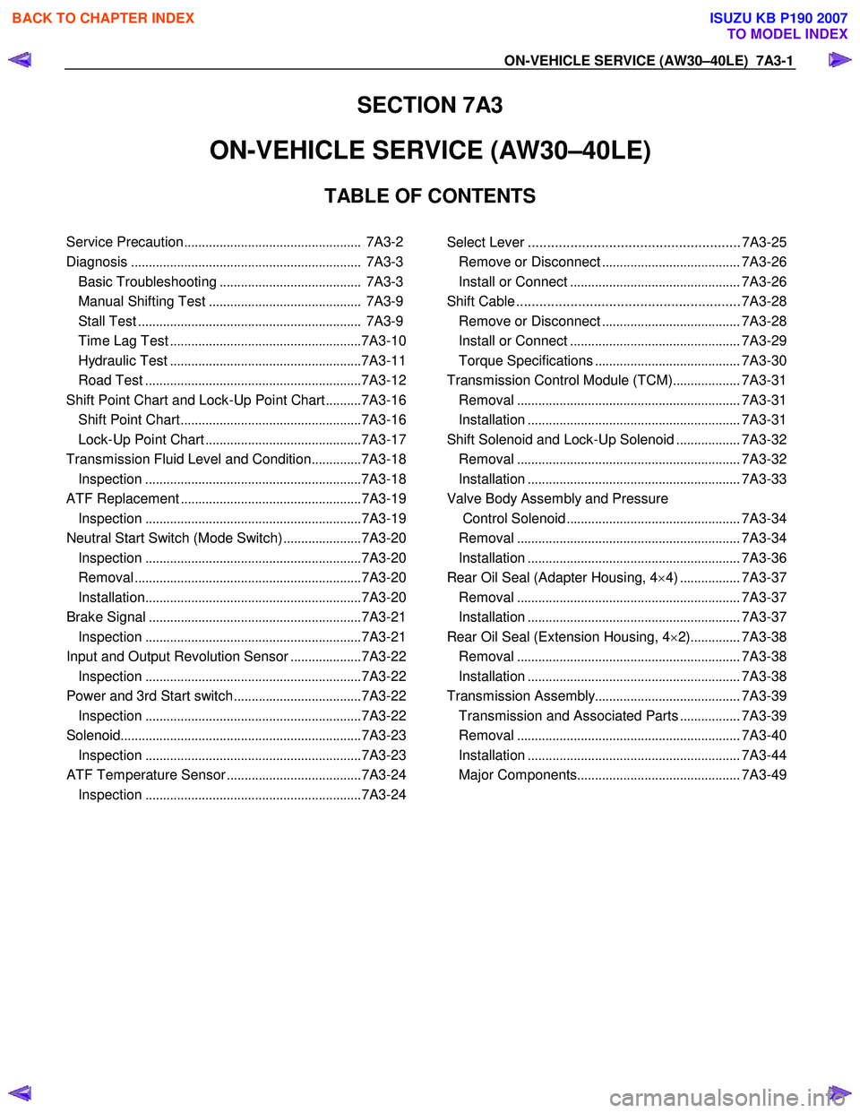
SECTION 7A3
ON-VEHICLE SERVICE (AW30–40LE)
TABLE OF CONTENTS
Service Precaution .................................................. 7A3-2
Diagnosis ................................................................. 7A3-3
Basic Troubleshooting ........................................ 7A3-3
Manual Shifting Test ........................................... 7A3-9
Stall Test ............................................................... 7A3-9
Time Lag Test ...................................................... 7A3-10
Hydraulic Test ...................................................... 7A3-11
Road Test ............................................................. 7A3-12
Shift Point Chart and Lock-Up Point Chart ..........7A3-16
Shift Point Chart ................................................... 7A3-16
Lock-Up Point Chart ............................................ 7A3-17
Transmission Fluid Level and Condition ..............7A3-18
Inspection ............................................................. 7A3-18
ATF Replacement ................................................... 7A3-19
Inspection ............................................................. 7A3-19
Neutral Start Switch (Mode Switch) ......................7A3-20
Inspection ............................................................. 7A3-20
Removal ................................................................ 7A3-20
Installation ............................................................. 7A3-20
Brake Signal ............................................................ 7A3-21
Inspection ............................................................. 7A3-21
Input and Output Revolution Sensor ....................7A3-22
Inspection ............................................................. 7A3-22
Power and 3rd Start switch ....................................7A3-22
Inspection ............................................................. 7A3-22
Solenoid .................................................................... 7A3-23
Inspection ............................................................. 7A3-23
ATF Temperature Sensor ......................................7A3-24
Inspection ............................................................. 7A3-24
Select Lever ....................................................... 7A3-25 Remove or Disconnect .......................................7A3-26
Install or Connect ................................................ 7A3-26
Shift Cable .......................................................... 7A3-28 Remove or Disconnect .......................................7A3-28
Install or Connect ................................................ 7A3-29
Torque Specifications ......................................... 7A3-30
Transmission Control Module (TCM) ...................7A3-31
Removal ............................................................... 7A3-31
Installation ............................................................ 7A3-31
Shift Solenoid and Lock-Up Solenoid ..................7A3-32
Removal ............................................................... 7A3-32
Installation ............................................................ 7A3-33
Valve Body Assembly and Pressure Control Solenoid ................................................. 7A3-34
Removal ............................................................... 7A3-34
Installation ............................................................ 7A3-36
Rear Oil Seal (Adapter Housing, 4 ×4) ................. 7A3-37
Removal ............................................................... 7A3-37
Installation ............................................................ 7A3-37
Rear Oil Seal (Extension Housing, 4 ×2) .............. 7A3-38
Removal ............................................................... 7A3-38
Installation ............................................................ 7A3-38
Transmission Assembly .........................................7A3-39
Transmission and Associated Parts .................7A3-39
Removal ............................................................... 7A3-40
Installation ............................................................ 7A3-44
Major Components .............................................. 7A3-49
BACK TO CHAPTER INDEX
TO MODEL INDEX
ISUZU KB P190 2007
Page 4087 of 6020

7A3-2 ON-VEHICLE SERVICE (AW30–40LE)
Service Precaution
WARNING: THIS VEHICLE HAS A SUPPLEMENTAL
RESTRAINT SYSTEM (SRS). REFER TO THE SRS
COMPONENT AND WIRING LOCATION VIEW IN
ORDER TO DETERMINE WHETHER YOU ARE
PERFORMING SERVICE ON OR NEAR THE SRS
COMPONENTS OR THE SRS WIRING. WHEN YOU
ARE PERFORMING SERVICE ON OR NEAR THE
SRS COMPONENTS OR THE SRS WIRING, REFER
TO THE SRS SERVICE INFORMATION. FAILURE TO
FOLLOW WARNINGS COULD RESULT IN
POSSIBLE AIR BAG DEPLOYMENT, PERSONAL
INJURY, OR OTHERWISE UNNEEDED SRS SYSTEM
REPAIRS.
CAUTION: Always use the correct fastener in the
proper location. When you replace a fastener, use
ONLY the exact part number for that application.
ISUZU/GM will call out those fasteners that require
a replacement after removal. ISUZU/GM will also
call out the fasteners that require thread lockers o
r
thread sealant. UNLESS OTHERWISE SPECIFIED,
do not use supplemental coatings (Paints, greases,
or other corrosion inhibitors) on threaded fasteners
or fastener joint interfaces. Generally, such
coatings adversely affect the fastener torque and
the joint clamping force, and may damage the
fastener. When you install fasteners, use the
correct tightening sequence and specifications.
Following these instructions can help you avoid
damage to parts and systems.
BACK TO CHAPTER INDEX
TO MODEL INDEX
ISUZU KB P190 2007
Page 4097 of 6020

7A3-12 ON-VEHICLE SERVICE (AW30–40LE)
Measure Line Pressure
1. Fully apply the parking brake and chock the four
wheels.
2. Start the engine and check idling rpm.
3. Select into “D" position, step down strongly on the brake pedal with your left foot and while
manipulating the accelerator pedal with the right
foot, measure the line pressures at the engine
speeds specified in the table.
4. In the same manner, perform the test in “R" position.
Line pressure kPa (kg/cm
2/psi) Engine
speed “D" position “R" position
Idling 349 – 408
(3.6 – 4.2 /51 – 59) 577 – 675
(5.9 – 6.9/84 – 98)
Stall 1,206 – 1,353
(12.3–13.8/175–196) 1,646 – 1,979
(16.8–20.2/239–287)
Evaluation
1. If the measured values at all positions are higher
than specified:
• Pressure control solenoid defective
• Primary regulator valve defective
2. If the measured values at all positions are lowe
r
than specified:
• Primary regulator valve defective
• Oil pump defective
• Pressure control solenoid defective
3. If pressure is low in “D" position only:
• “D" position circuit fluid leakage
4. If pressure is low in “R" position only:
• “R" position circuit fluid leakage
Road Test
NOTE: Perform the test at normal operating fluid
temperature (50 – 80 °C or 122 – 176 °F).
“D" Position Test in “NORMAL", and
“POWER" Pattern
Select into the “D" position and hold the accelerator
pedal constant at the 50% and 100% throttle valve
opening positions.
Push in one of the pattern selector buttons and check
the following:
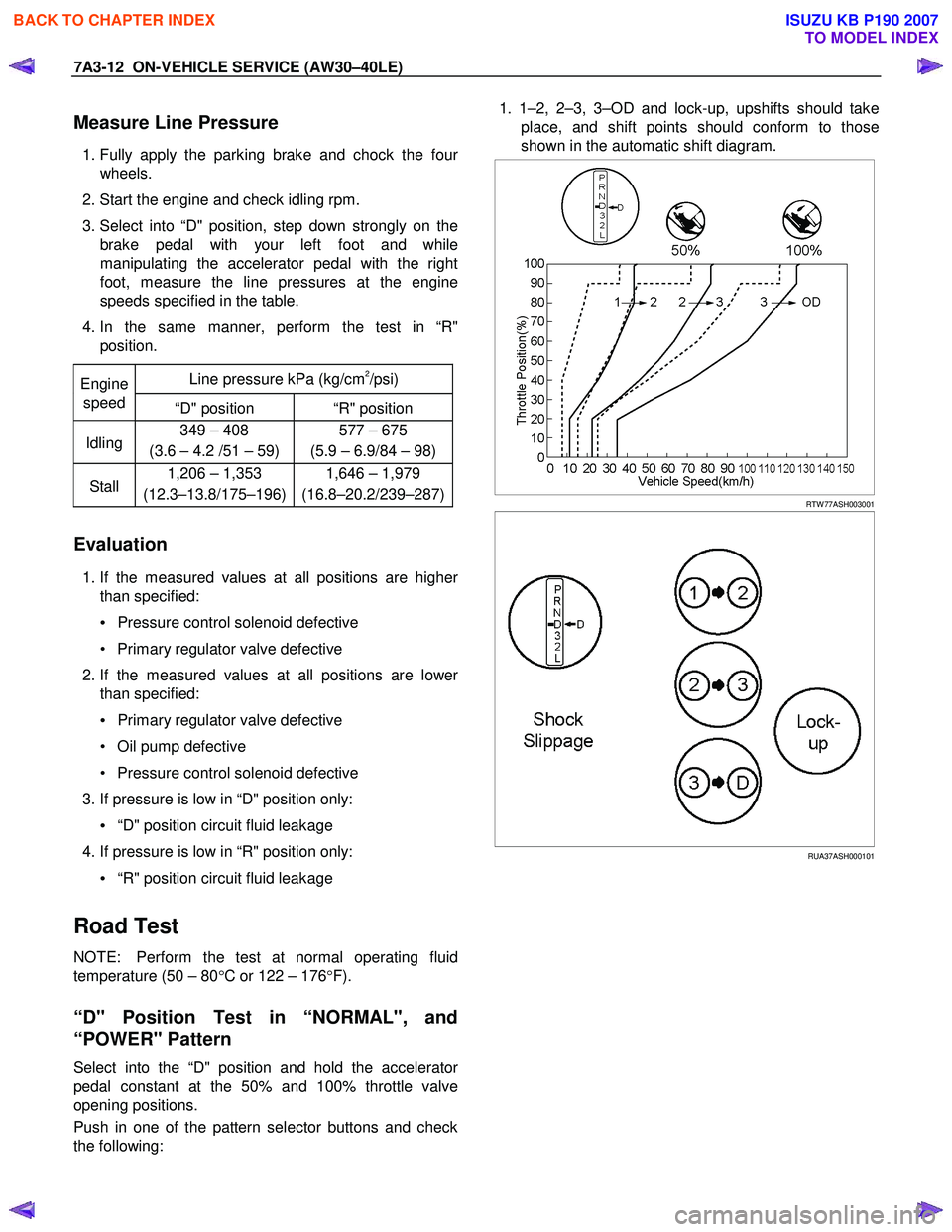
1. 1–2, 2–3, 3–OD and lock-up, upshifts should take
place, and shift points should conform to those
shown in the automatic shift diagram.
RTW 77ASH003001
RUA37ASH000101
BACK TO CHAPTER INDEX
TO MODEL INDEX
ISUZU KB P190 2007
Page 4098 of 6020

ON-VEHICLE SERVICE (AW30–40LE) 7A3-13
Evaluation
i. If there is no 1→2 upshift:
• Solenoid S2 is stuck
• 1–2 shift valve is stuck
ii. If there is no 2 →3 upshift:
• Solenoid S1 is stuck
• 2–3 shift valve is stuck
iii. If there is no 3 →OD upshift (throttle valve opening
1/2):
• Solenoid S2 is stuck
• 3–OD shift valve is stuck
iv. If the shift point is defective: Refer to TROUBLESHOOTING CHART in this
section.
v. If the lock-up is defective: Refer to TROUBLESHOOTING CHART in this
section.
2. In the same manner, check the shock and slip at the 1→ 2, 2 →3 and 3 →OD upshifts.
NOTE: Drive the vehicle on level ground.
Evaluation
If the shock is excessive:
Refer to TROUBLESHOOTING CHART in this section. 3. Run at “D" position lock-up or OD gear and check fo
r
abnormal noise and vibration.
NOTE: The check for the cause of abnormal noise and
vibration must be made with extreme care as it could
also be due to loss of balance in the propeller shaft,
differential, the torque converter, etc. or insufficient
bending, rigidity, etc. in the power train.
RUW 37ASH000201
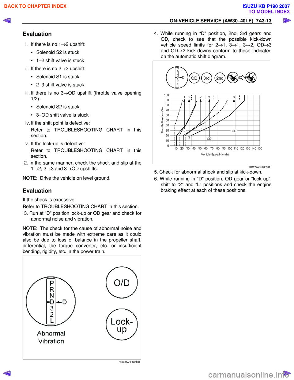
4. W hile running in “D" position, 2nd, 3rd gears and
OD, check to see that the possible kick-down
vehicle speed limits for 2 →1, 3 →1, 3 →2, OD →3
and OD →2 kick-downs conform to those indicated
on the automatic shift diagram.
RTW 77ASH003101
5. Check for abnormal shock and slip at kick-down.
6. W hile running in “D" position, OD gear or “lock-up", shift to “2" and “L" positions and check the engine
braking effect at each of these positions.
BACK TO CHAPTER INDEX
TO MODEL INDEX
ISUZU KB P190 2007
Page 4099 of 6020

7A3-14 ON-VEHICLE SERVICE (AW30–40LE)
Evaluation
i. If there is no engine braking effect in the “2"
position:
• Second coast (No.1) brake is defective.
ii. If there is no engine braking effect in the “L" position:
• First and reverse (No.3) brake is defective.
RUW 37ASH000301
iii. Also check to see that downshift is made from 3 to
2 or from OD to 3 and then to 2 immediately and
that 2 →1 downshift point is within the limits shown
in the diagram when tested by releasing the
accelerator pedal and operaing into “L" position
while driving in the third gear or in overdrive.
RUW 37ASH000401
“2" Position Test
Select into “2" position and, while driving with the
accelerator pedal held constantly at the specified point
(throttle valve opening 50% and 100%), push in one o
f
the pattern selectors and check on the following points.
1.
At each of the above throttle openings, check to see
that the 1 →2 upshift takes place and that the shift
points conform to those shown on the automatic
shift diagram.
NOTE: There is no OD and no lock-up in the “2"
position.
RTW 77ASH003201
2. W hile running in the “2" position and 2nd gear,
release the accelerator pedal and check the
engine's braking effect.
3. Check for 2 →1 downshift and abnormal noise at
acceleration and deceleration, and for shock at
upshift and downshift.
RUW 37ASH000501
BACK TO CHAPTER INDEX
TO MODEL INDEX
ISUZU KB P190 2007
Page 4100 of 6020

ON-VEHICLE SERVICE (AW30–40LE) 7A3-15
“L" Position Test
1. W hile running above 80 km/h (50 mph) in the “D"
position, release your foot from the accelerato
r
pedal and shift into the “L" position.
Then check to see that the 2 →1 downshift occurs at
the specified point shown on the automatic shift
diagram.
RUW 37ASH000601
2. W hile running in the “L" position, check to see that
there is no upshift to 2nd gear.
3. W hile running in the “L" position, release the accelerator pedal and check the engine braking
effect.
4. Check for abnormal noise during acceleration and deceleration.
RUW 37ASH000701
“R" Position Test
Select into the “R" position and, while starting at full
throttle, check for slipping.
RUW 37ASH000801
“P" Position Test
Stop the vehicle on a grade (more than 9%) and afte
r
shifting into the “P" position, release the parking brake.
Then check to see that the parking lock pawl holds the
vehicle in place.
BACK TO CHAPTER INDEX
TO MODEL INDEX
ISUZU KB P190 2007