lock ISUZU KB P190 2007 Workshop Repair Manual
[x] Cancel search | Manufacturer: ISUZU, Model Year: 2007, Model line: KB P190, Model: ISUZU KB P190 2007Pages: 6020, PDF Size: 70.23 MB
Page 4101 of 6020
7A3-16 ON-VEHICLE SERVICE (AW30–40LE)
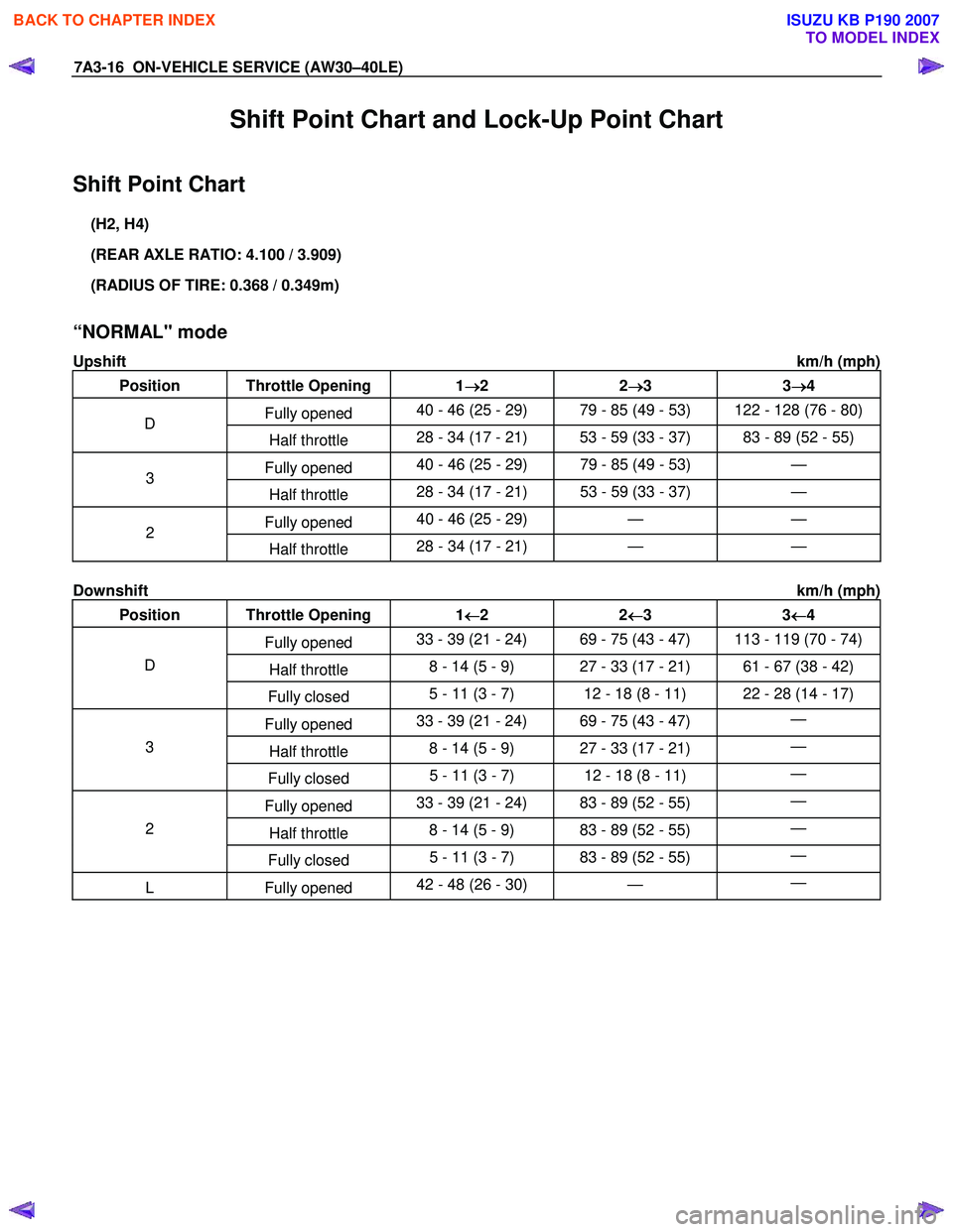
Shift Point Chart and Lock-Up Point Chart
Shift Point Chart
(H2, H4)
(REAR AXLE RATIO: 4.100 / 3.909)
(RADIUS OF TIRE: 0.368 / 0.349m)
“NORMAL" mode
Upshift km/h (mph)
Position Throttle Opening 1 →
→→
→
2 2 →
→→
→
3 3 →
→→
→
4
Fully opened 40 - 46 (25 - 29) 79 - 85 (49 - 53) 122 - 128 (76 - 80) D
Half throttle 28 - 34 (17 - 21) 53 - 59 (33 - 37) 83 - 89 (52 - 55)
Fully opened 40 - 46 (25 - 29) 79 - 85 (49 - 53) — 3
Half throttle 28 - 34 (17 - 21) 53 - 59 (33 - 37)
—
Fully opened 40 - 46 (25 - 29) — — 2
Half throttle 28 - 34 (17 - 21)
— —
Downshift km/h (mph)
Position Throttle Opening 1 ←
←←
←
2 2 ←
←←
←
3 3 ←
←←
←
4
Fully opened 33 - 39 (21 - 24) 69 - 75 (43 - 47) 113 - 119 (70 - 74)
Half throttle 8 - 14 (5 - 9) 27 - 33 (17 - 21) 61 - 67 (38 - 42) D
Fully closed 5 - 11 (3 - 7) 12 - 18 (8 - 11) 22 - 28 (14 - 17)
Fully opened 33 - 39 (21 - 24) 69 - 75 (43 - 47)
—
Half throttle 8 - 14 (5 - 9) 27 - 33 (17 - 21)
— 3
Fully closed 5 - 11 (3 - 7) 12 - 18 (8 - 11)
—
Fully opened 33 - 39 (21 - 24) 83 - 89 (52 - 55)
—
Half throttle 8 - 14 (5 - 9) 83 - 89 (52 - 55)
— 2
Fully closed 5 - 11 (3 - 7) 83 - 89 (52 - 55)
—
L Fully
opened 42 - 48 (26 - 30)
— —
BACK TO CHAPTER INDEX
TO MODEL INDEX
ISUZU KB P190 2007
Page 4102 of 6020
ON-VEHICLE SERVICE (AW30–40LE) 7A3-17
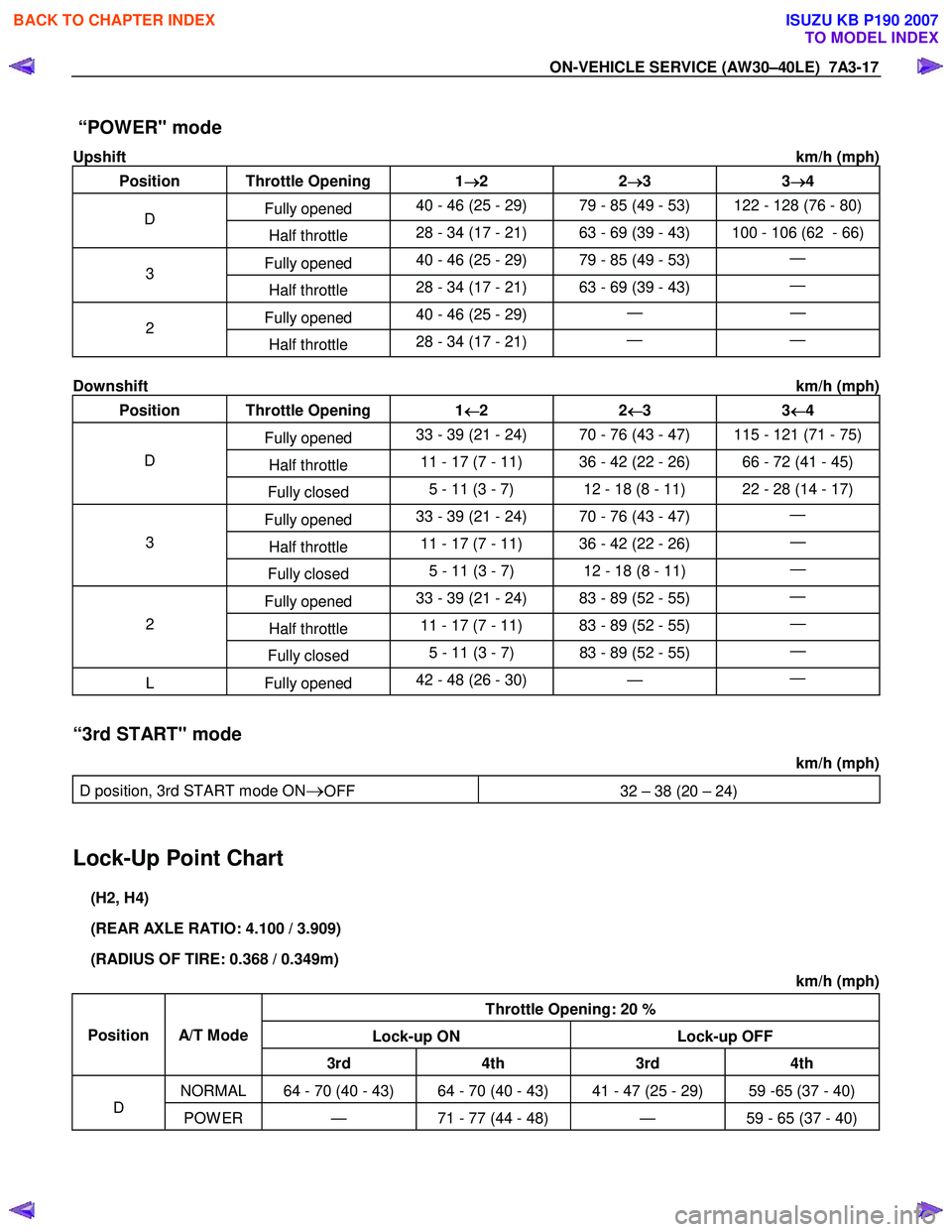
“POWER" mode
Upshift km/h (mph)
Position Throttle Opening 1 →
→→
→
2 2 →
→→
→
3 3 →
→→
→
4
Fully opened 40 - 46 (25 - 29) 79 - 85 (49 - 53) 122 - 128 (76 - 80) D
Half throttle 28 - 34 (17 - 21) 63 - 69 (39 - 43) 100 - 106 (62 - 66)
Fully opened 40 - 46 (25 - 29) 79 - 85 (49 - 53)
— 3
Half throttle 28 - 34 (17 - 21) 63 - 69 (39 - 43)
—
Fully opened 40 - 46 (25 - 29)
— — 2
Half throttle 28 - 34 (17 - 21)
— —
Downshift km/h (mph)
Position Throttle Opening 1 ←
←←
←
2 2 ←
←←
←
3 3 ←
←←
←
4
Fully opened 33 - 39 (21 - 24) 70 - 76 (43 - 47) 115 - 121 (71 - 75)
Half throttle 11 - 17 (7 - 11) 36 - 42 (22 - 26) 66 - 72 (41 - 45) D
Fully closed 5 - 11 (3 - 7) 12 - 18 (8 - 11) 22 - 28 (14 - 17)
Fully opened 33 - 39 (21 - 24) 70 - 76 (43 - 47)
—
Half throttle 11 - 17 (7 - 11) 36 - 42 (22 - 26)
— 3
Fully closed 5 - 11 (3 - 7) 12 - 18 (8 - 11)
—
Fully opened 33 - 39 (21 - 24) 83 - 89 (52 - 55)
—
Half throttle 11 - 17 (7 - 11) 83 - 89 (52 - 55)
— 2
Fully closed 5 - 11 (3 - 7) 83 - 89 (52 - 55)
—
L Fully
opened 42 - 48 (26 - 30)
— —
“3rd START" mode
km/h (mph)
D position, 3rd START mode ON
→OFF 32 – 38 (20 – 24)
Lock-Up Point Chart
(H2, H4)
(REAR AXLE RATIO: 4.100 / 3.909)
(RADIUS OF TIRE: 0.368 / 0.349m) km/h (mph)
Throttle Opening: 20 %
Lock-up ON Lock-up OFF
Position
A/T Mode
3rd 4th 3rd 4th
NORMAL 64 - 70 (40 - 43) 64 - 70 (40 - 43) 41 - 47 (25 - 29) 59 -65 (37 - 40)
D POW ER — 71 - 77 (44 - 48) — 59 - 65 (37 - 40)
BACK TO CHAPTER INDEX
TO MODEL INDEX
ISUZU KB P190 2007
Page 4105 of 6020
7A3-20 ON-VEHICLE SERVICE (AW30–40LE)
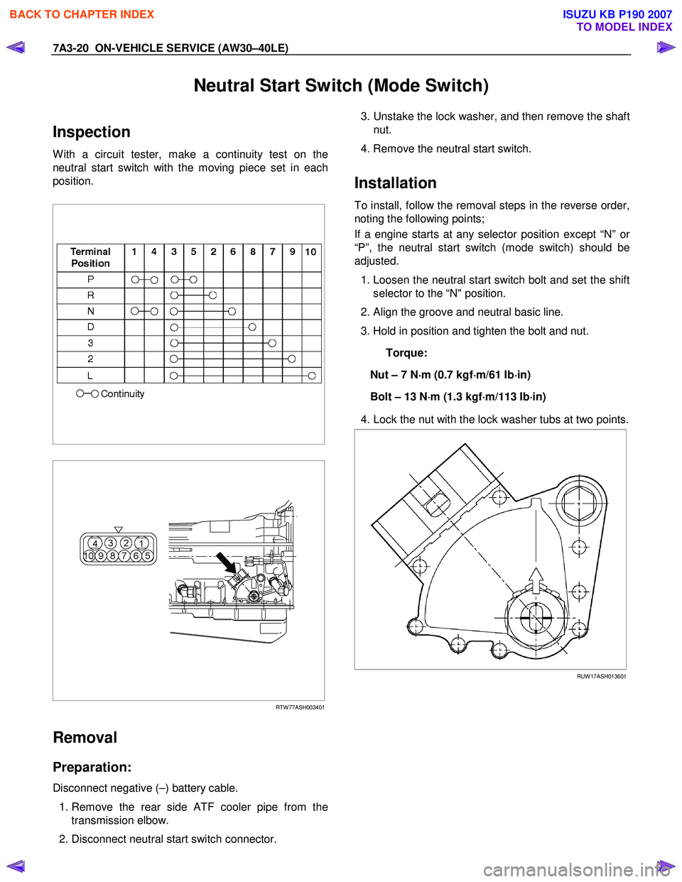
Neutral Start Switch (Mode Switch)
Inspection
W ith a circuit tester, make a continuity test on the
neutral start switch with the moving piece set in each
position.
RTW 77ASH003401
Removal
Preparation:
Disconnect negative (–) battery cable.
1. Remove the rear side ATF cooler pipe from the
transmission elbow.
2. Disconnect neutral start switch connector.
3. Unstake the lock washer, and then remove the shaft
nut.
4. Remove the neutral start switch.
Installation
To install, follow the removal steps in the reverse order,
noting the following points;
If a engine starts at any selector position except “N” o
r
“P”, the neutral start switch (mode switch) should be
adjusted.
1. Loosen the neutral start switch bolt and set the shift
selector to the “N" position.
2. Align the groove and neutral basic line.
3. Hold in position and tighten the bolt and nut.
Torque:
Nut – 7 N ⋅
⋅⋅
⋅
m (0.7 kgf ⋅
⋅⋅
⋅
m/61 Ib ⋅
⋅⋅
⋅
in)
Bolt – 13 N ⋅
⋅⋅
⋅
m (1.3 kgf ⋅
⋅⋅
⋅
m/113 Ib ⋅
⋅⋅
⋅
in)
4. Lock the nut with the lock washer tubs at two points.
RUW 17ASH013601
BACK TO CHAPTER INDEX
TO MODEL INDEX
ISUZU KB P190 2007
Page 4107 of 6020
7A3-22 ON-VEHICLE SERVICE (AW30–40LE)
Input and Output Revolution Sensor
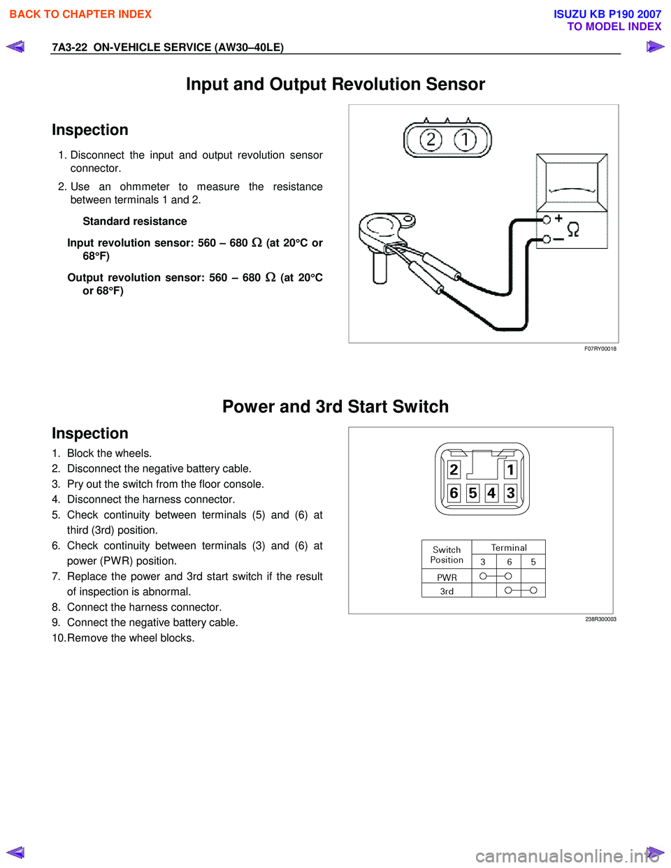
Inspection
1. Disconnect the input and output revolution sensor
connector.
2. Use an ohmmeter to measure the resistance between terminals 1 and 2.
Standard resistance
Input revolution sensor: 560 – 680
Ω
ΩΩ
Ω (at 20
°
°°
°
Cor
68 °
°°
°
F)
Output revolution sensor: 560 – 680
Ω
ΩΩ
Ω (at 20
°
°°
°
C
or 68 °
°°
°
F)
F07RY00018
Power and 3rd Start Switch
Inspection
1. Block the wheels.
2. Disconnect the negative battery cable.
3. Pry out the switch from the floor console.
4. Disconnect the harness connector.
5. Check continuity between terminals (5) and (6) at third (3rd) position.
6. Check continuity between terminals (3) and (6) at power (PW R) position.
7. Replace the power and 3rd start switch if the result of inspection is abnormal.
8. Connect the harness connector.
9. Connect the negative battery cable.
10. Remove the wheel blocks.
238R300003
BACK TO CHAPTER INDEX
TO MODEL INDEX
ISUZU KB P190 2007
Page 4108 of 6020
ON-VEHICLE SERVICE (AW30–40LE) 7A3-23
Solenoid
Inspection
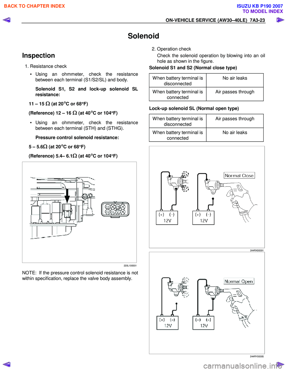
1. Resistance check
• Using an ohmmeter, check the resistance
between each terminal (S1/S2/SL) and body.
Solenoid S1, S2 and lock-up solenoid SL
resistance:
11 – 15
Ω
ΩΩ
Ω (at 20°
°°
°C or 68
°
°°
°
F)
(Reference) 12 – 16
Ω
ΩΩ
Ω (at 40°
°°
°C or 104
°
°°
°
F)
• Using an ohmmeter, check the resistance
between each terminal (STH) and (STHG).
Pressure control solenoid resistance:
5 – 5.6
Ω
ΩΩ
Ω (at 20°
°°
°C or 68
°
°°
°
F)
(Reference) 5.4– 6.1
Ω
ΩΩ
Ω (at 40°
°°
°C or 104
°
°°
°
F)
220L100001
NOTE: If the pressure control solenoid resistance is not
within specification, replace the valve body assembly.
2. Operation check
Check the solenoid operation by blowing into an oil
hole as shown in the figure.
Solenoid S1 and S2 (Normal close type)
W hen battery terminal is disconnected No air leaks
W hen battery terminal is
connected Air passes through
Lock-up solenoid SL (Normal open type)
W hen battery terminal is disconnected Air passes through
W hen battery terminal is
connected No air leaks
244RX00001
244RY00005
BACK TO CHAPTER INDEX
TO MODEL INDEX
ISUZU KB P190 2007
Page 4110 of 6020
ON-VEHICLE SERVICE (AW30–40LE) 7A3-25
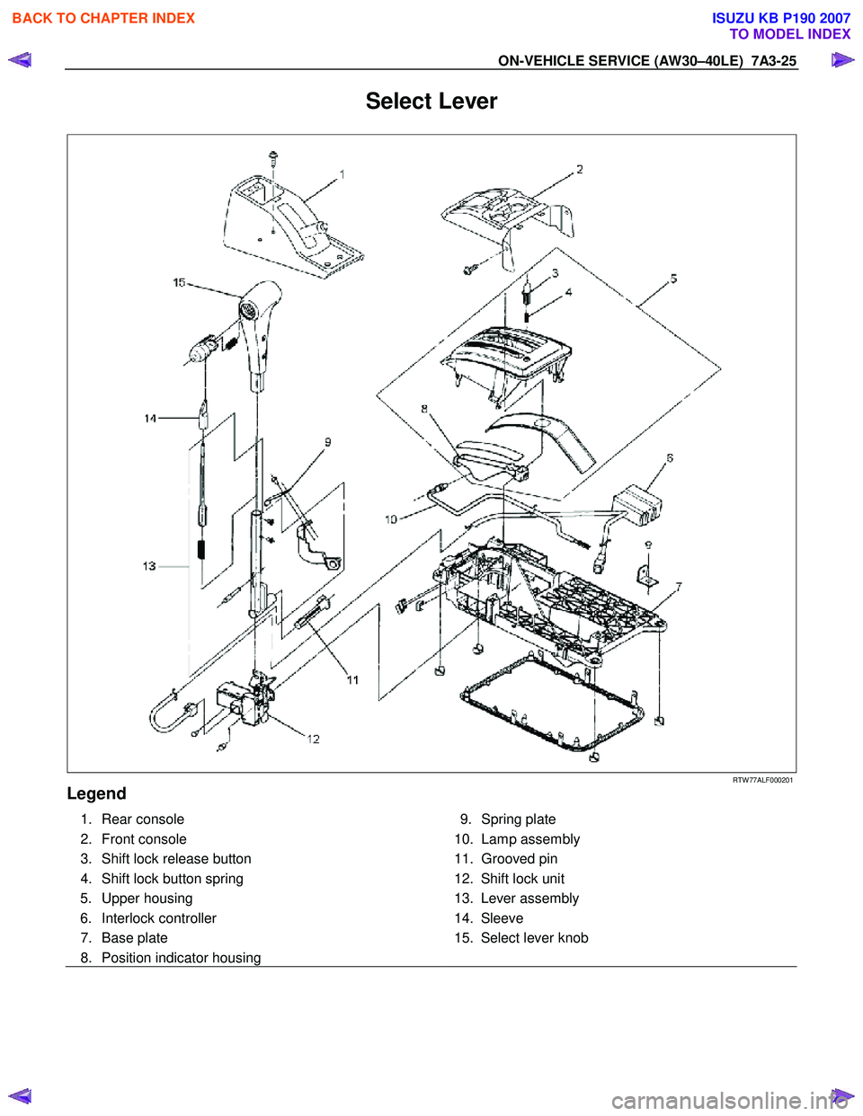
Select Lever
RTW 77ALF000201
Legend
1. Rear console
2. Front console
3. Shift lock release button
4. Shift lock button spring 5. Upper housing
6. Interlock controller
7. Base plate
8. Position indicator housing
9. Spring plate
10. Lamp assembly
11. Grooved pin
12. Shift lock unit
13. Lever assembly
14. Sleeve
15. Select lever knob
BACK TO CHAPTER INDEX
TO MODEL INDEX
ISUZU KB P190 2007
Page 4111 of 6020
7A3-26 ON-VEHICLE SERVICE (AW30–40LE)
Remove or Disconnect
1. Block the wheels.
2. Disconnect the negative battery cable.
3. Remove the rear console and the front console.
4. Remove the 2 screws fixing the select lever knob.
5. Remove the knob together with the knob button and spring from the lever.
6. Turn the sleeve counterclockwise to remove it. Make a note of the number of turns required to free
the sleeve.
7. Remove the harness connectors from the base plate.
8. Remove the upper housing (held in place by 4 latched fasteners).
9. Remove the lamp assembly by turning it counterclockwise.
10. Remove the spring plate.
11. Remove the grooved pin.
12. Disconnect the shift cable from the select lever.
13. Remove the lever assembly by pressing the rod down (lever in N position).
14. Remove the harness connectors from the shift lock unit, then remove the shift lock unit.
15. Remove the interlock controller.
16. If the replacement of shift lock release button o
r
shift lock button spring is required, remove the
position indicator housing, the shift lock button
spring and shift lock release button can be
removed.
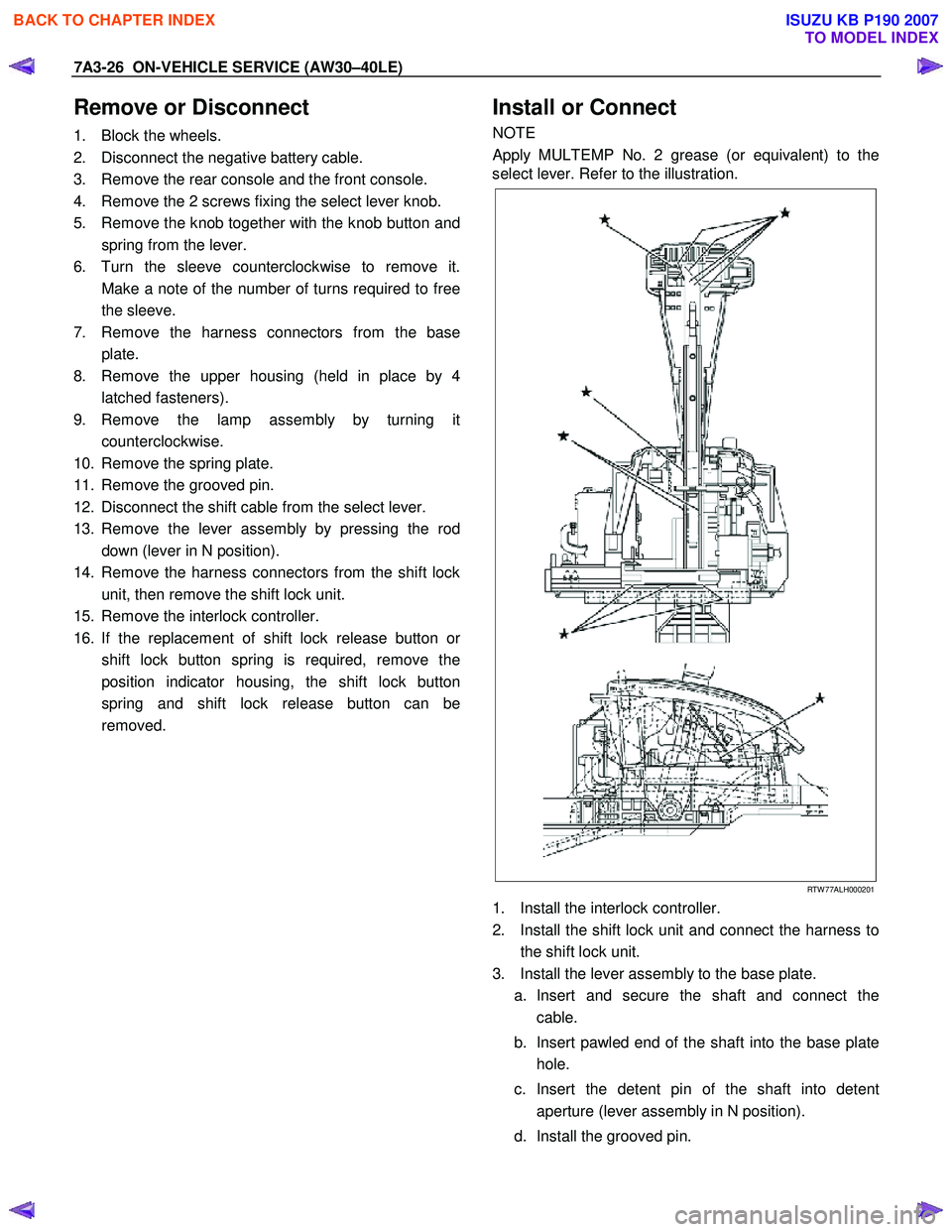
Install or Connect
NOTE
Apply MULTEMP No. 2 grease (or equivalent) to the
select lever. Refer to the illustration.
RTW 77ALH000201
1. Install the interlock controller.
2. Install the shift lock unit and connect the harness to the shift lock unit.
3. Install the lever assembly to the base plate. a. Insert and secure the shaft and connect the cable.
b. Insert pawled end of the shaft into the base plate hole.
c. Insert the detent pin of the shaft into detent aperture (lever assembly in N position).
d. Install the grooved pin.
BACK TO CHAPTER INDEX
TO MODEL INDEX
ISUZU KB P190 2007
Page 4112 of 6020
ON-VEHICLE SERVICE (AW30–40LE) 7A3-27
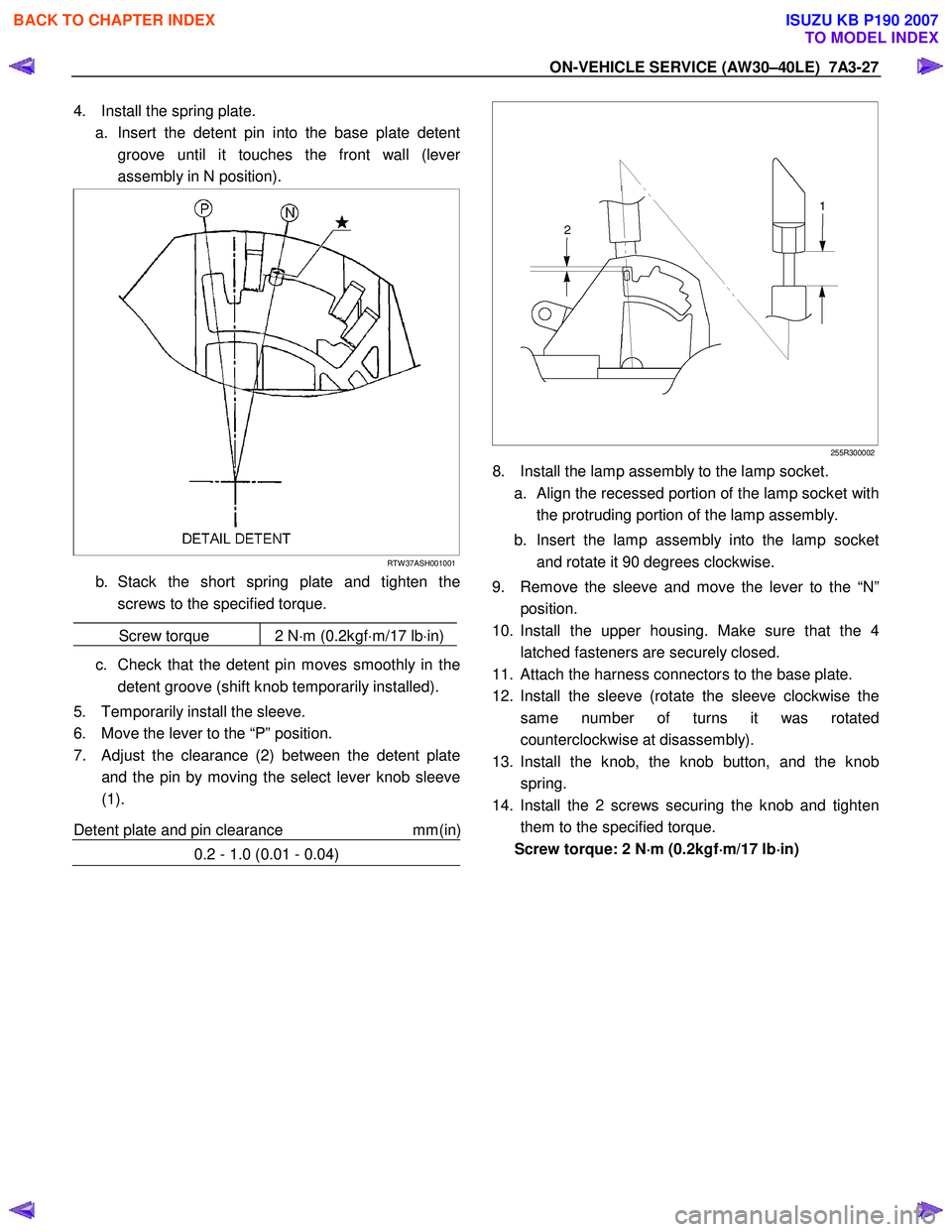
4. Install the spring plate.
a. Insert the detent pin into the base plate detent groove until it touches the front wall (leve
r
assembly in N position).
RTW 37ASH001001
b. Stack the short spring plate and tighten thescrews to the specified torque.
Screw torque 2 N ⋅m (0.2kgf ⋅m/17 lb ⋅in)
c. Check that the detent pin moves smoothly in the
detent groove (shift knob temporarily installed).
5. Temporarily install the sleeve.
6. Move the lever to the “P” position.
7. Adjust the clearance (2) between the detent plate and the pin by moving the select lever knob sleeve
(1).
Detent plate and pin clearance mm(in
)
0.2 - 1.0 (0.01 - 0.04)
255R300002
8. Install the lamp assembly to the lamp socket.
a.
Align the recessed portion of the lamp socket with
the protruding portion of the lamp assembly.
b. Insert the lamp assembly into the lamp socket and rotate it 90 degrees clockwise.
9. Remove the sleeve and move the lever to the “N” position.
10. Install the upper housing. Make sure that the 4 latched fasteners are securely closed.
11. Attach the harness connectors to the base plate.
12. Install the sleeve (rotate the sleeve clockwise the same number of turns it was rotated
counterclockwise at disassembly).
13. Install the knob, the knob button, and the knob spring.
14. Install the 2 screws securing the knob and tighten them to the specified torque.
Screw torque: 2 N ⋅
⋅⋅
⋅
m (0.2kgf ⋅
⋅⋅
⋅
m/17 lb ⋅
⋅⋅
⋅
in)
BACK TO CHAPTER INDEX
TO MODEL INDEX
ISUZU KB P190 2007
Page 4113 of 6020
7A3-28 ON-VEHICLE SERVICE (AW30–40LE)
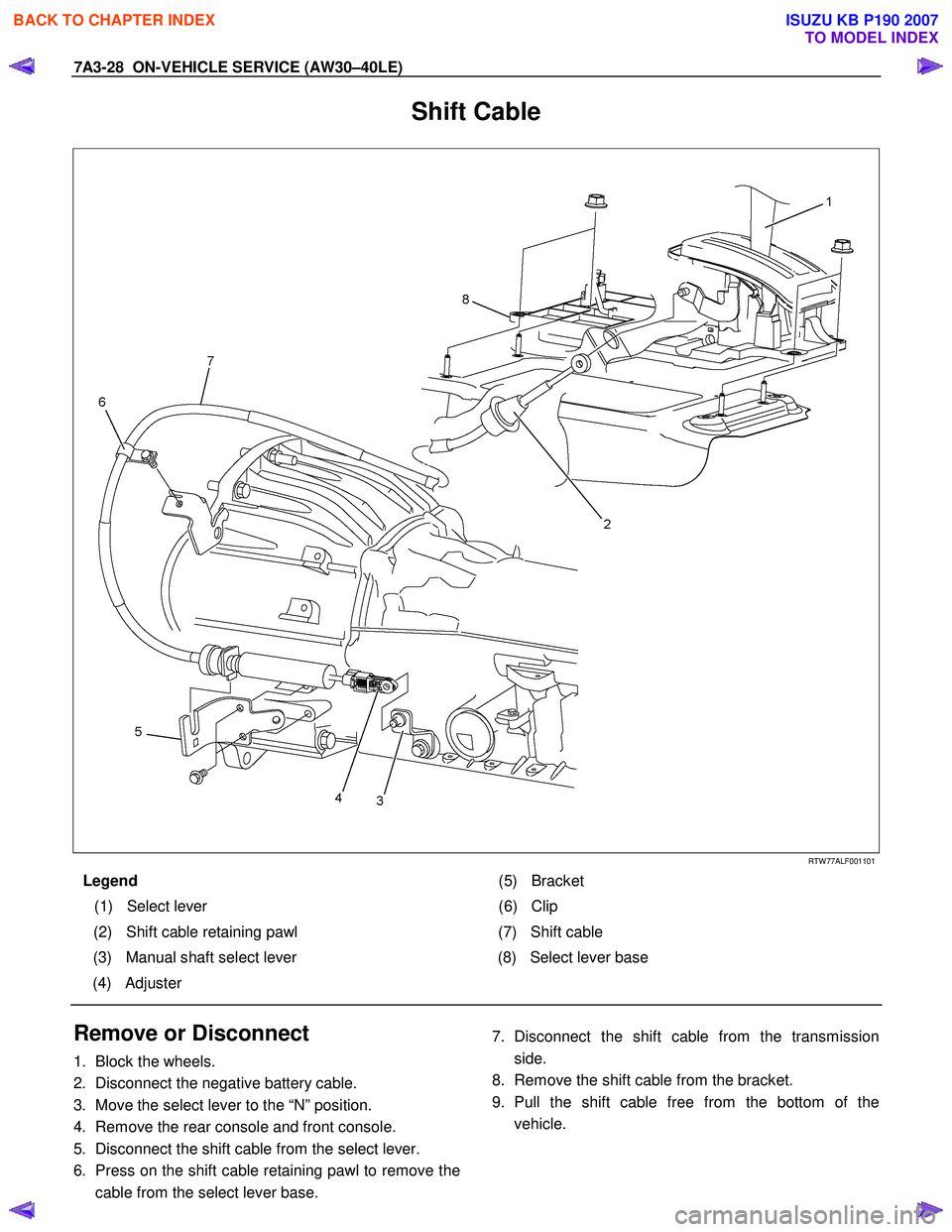
Shift Cable
RTW 77ALF001101
Legend (5) Bracket
(1) Select lever (6) Clip
(2) Shift cable retaining pawl (7) Shift cable
(3) Manual shaft select lever (8) Select lever base
(4) Adjuster
Remove or Disconnect
1. Block the wheels.
2. Disconnect the negative battery cable.
3. Move the select lever to the “N” position.
4. Remove the rear console and front console.
5. Disconnect the shift cable from the select lever.
6. Press on the shift cable retaining pawl to remove the
cable from the select lever base.
7. Disconnect the shift cable from the transmission
side.
8. Remove the shift cable from the bracket.
9. Pull the shift cable free from the bottom of the
vehicle.
BACK TO CHAPTER INDEX
TO MODEL INDEX
ISUZU KB P190 2007
Page 4114 of 6020
ON-VEHICLE SERVICE (AW30–40LE) 7A3-29
Install or Connect
1. Install the shift cable toward the inside of the cabin
from the bottom of the vehicle.
2. Push the shift cable into the select lever base.
3. Connect the shift cable to the select lever.
4. Fix the shift cable to the bracket.
Install the clip on the marking of shift cable.
5. Check that the select lever is in the “N” position.
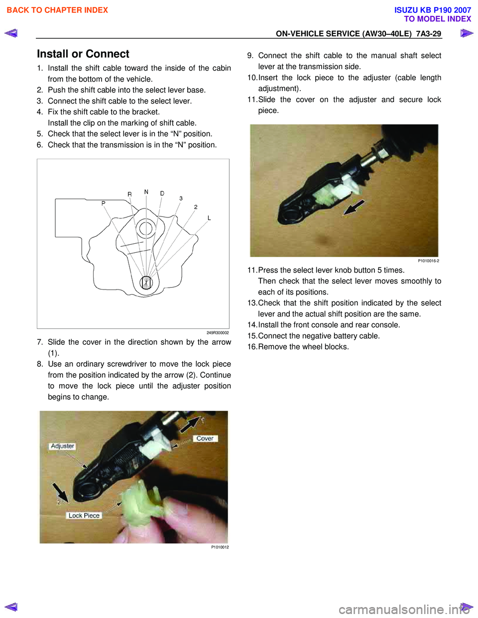
6. Check that the transmission is in the “N” position.
249R300002
7. Slide the cover in the direction shown by the arrow
(1).
8. Use an ordinary screwdriver to move the lock piece
from the position indicated by the arrow (2). Continue
to move the lock piece until the adjuster position
begins to change.
P1010012
9. Connect the shift cable to the manual shaft select
lever at the transmission side.
10. Insert the lock piece to the adjuster (cable length
adjustment).
11. Slide the cover on the adjuster and secure lock
piece.
P1010016-2
11. Press the select lever knob button 5 times.
Then check that the select lever moves smoothly to each of its positions.
13. Check that the shift position indicated by the select
lever and the actual shift position are the same.
14. Install the front console and rear console.
15. Connect the negative battery cable.
16. Remove the wheel blocks.
BACK TO CHAPTER INDEX
TO MODEL INDEX
ISUZU KB P190 2007