width ISUZU KB P190 2007 Workshop Repair Manual
[x] Cancel search | Manufacturer: ISUZU, Model Year: 2007, Model line: KB P190, Model: ISUZU KB P190 2007Pages: 6020, PDF Size: 70.23 MB
Page 4345 of 6020

TRANSMISSION CONTROL SYSTEM (JR405E) 7A2-61
DTC P0758 (Flash Code 32)
Circuit Description
The 2-4 brake solenoid valve controls fluid acting on
spool valves in the 2-4 brake hydraulic circuits, which
then controls 2-4 brake apply and release. The
solenoid valve is installed to the lower part of the valve
body assembly. The TCM controls the solenoid valve
by a duty cycle (pulse width modulation [PWM]) signal
based on the commanded gear position. The solenoid
valve provides a smooth gearshift by operating on a
duty cycle percentage of ON time. The TCM monitors
the 2-4 brake solenoid valve operating status through
the feedback circuit. If the TCM detects an improper
voltage level on the control circuit, this DTC will set.
Condition for Running the DTC • The ignition switch is ON.
Condition for Setting the DTC • The TCM detects an open circuit or short circuit on the 2-4 brake solenoid valve control circuit.
Action Taken When the DTC Sets • The TCM blinks the Check Trans lamp when the diagnostic runs and fails.
During the vehicle running;
• The TCM holds the last gear position when the diagnostic runs and fails.
• The TCM stops 2-4 brake solenoid valve. • The TCM inhibits lock up control.
After the vehicle stopped;
• The TCM stops all shift solenoid valves and fixes to the 3rd gear. If a fail-safe valve problem is
detected, the shift solenoid valves are not stopped
but gear is fixed to the 3rd gear.
• The TCM stops PC solenoid valve.
Condition for Clearing the DTC • The TCM turns OFF the Check Trans lamp when the diagnostic runs and does not fail at next
ignition cycle.
• A current DTC clears when the diagnostic runs and does not fail at next ignition cycle.
Diagnostic Aids • If an intermittent condition is suspected, refer to Intermittent Conditions in this section.
• Use the Clutch, Brake, Solenoid and Pressure Switch Logic table to verify each component works
properly within the selected gear range.
Schematic Reference: Transmission Controls
Schematics
Connector End View Reference: Transmission
Controls Connector End Views or TCM Connector End
Views
Circuit/ System Testing DTC P0758
Step Action Value(s)Yes No
1 Did you perform the Diagnostic System Check -
Transmission Controls? —
Go to Step 2 Go to Diagnostic
System Check - Transmission Controls
2 1. Install a scan tool.
2. Turn OFF the ignition for 30 seconds.
3. Lift the driving wheels or drive the vehicle while observing the DTC Information with a
scan tool.
Is DTC P1875 also set? —
Go to DTC P1875 Go to Step 3
3 1. Park the vehicle.
2. Turn ON the ignition, with the engine OFF.
3. Perform the 2-4 Brake Solenoid control with a scan tool.
4. Command the solenoid valve ON and OFF.
Does the 2-4 brake solenoid valve click with each
command? —
Go to Diagnostic Aids Go to Step 4
BACK TO CHAPTER INDEX
TO MODEL INDEX
ISUZU KB P190 2007
Page 4348 of 6020

7A2-64 TRANSMISSION CONTROL SYSTEM (JR405E)
DTC P0763 (Flash Code 33)
Circuit Description
The high clutch solenoid valve controls fluid acting on
spool valves in the high clutch hydraulic circuits, which
then controls high clutch apply and release. The
solenoid valve is installed to the lower part of the valve
body assembly. The TCM controls the solenoid valve
by a duty cycle (pulse width modulation [PWM]) signal
based on the commanded gear position. The solenoid
valve provides a smooth gearshift by operating on a
duty cycle percentage of ON time. The TCM monitors
the high clutch solenoid valve operating status through
the feedback circuit. If the TCM detects an improper
voltage level on the control circuit, this DTC will set.
Condition for Running the DTC • The ignition switch is ON.
Condition for Setting the DTC • The TCM detects an open circuit or short circuit on the high clutch solenoid valve control circuit.
Action Taken When the DTC Sets • The TCM blinks the Check Trans lamp when the diagnostic runs and fails.
During the vehicle running;
• The TCM holds the last gear position when the diagnostic runs and fails.
• The TCM stops high clutch solenoid valve. • The TCM inhibits lock up control.
After the vehicle stopped;
• The TCM stops all shift solenoid valves and fixes to the 3rd gear. If a fail-safe valve problem is
detected, the shift solenoid valves are not stopped
but gear is fixed to the 3rd gear.
• The TCM stops PC solenoid valve.
Condition for Clearing the DTC • The TCM turns OFF the Check Trans lamp when the diagnostic runs and does not fail at next
ignition cycle.
• A current DTC clears when the diagnostic runs and does not fail at next ignition cycle.
Diagnostic Aids • If an intermittent condition is suspected, refer to Intermittent Conditions in this section.
• Use the Clutch, Brake, Solenoid and Pressure Switch Logic table to verify each component works
properly within the selected gear range.
Schematic Reference: Transmission Controls
Schematics
Connector End View Reference: Transmission
Controls Connector End Views or TCM Connector End
Views
Circuit/ System Testing DTC P0763
Step Action Value(s)Yes No
1 Did you perform the Diagnostic System Check -
Transmission Controls? —
Go to Step 2 Go to Diagnostic
System Check - Transmission Controls
2 1. Install a scan tool.
2. Turn OFF the ignition for 30 seconds.
3. Lift the driving wheels or drive the vehicle while observing the DTC Information with a
scan tool.
Is DTC P1875 also set? —
Go to DTC P1875 Go to Step 3
3 1. Park the vehicle.
2. Turn ON the ignition, with the engine OFF.
3. Perform the High Clutch Solenoid control with a scan tool.
4. Command the solenoid valve ON and OFF.
Does the high clutch solenoid valve click with each
command? —
Go to Diagnostic Aids Go to Step 4
BACK TO CHAPTER INDEX
TO MODEL INDEX
ISUZU KB P190 2007
Page 4351 of 6020

TRANSMISSION CONTROL SYSTEM (JR405E) 7A2-67
DTC P0768 (Flash Code 34)
Circuit Description
The low clutch solenoid valve controls fluid acting on
spool valves in the low clutch hydraulic circuits, which
then controls low clutch apply and release. The
solenoid valve is installed to the lower part of the valve
body assembly. The TCM controls the solenoid valve
by a duty cycle (pulse width modulation [PWM]) signal
based on the commanded gear position. The solenoid
valve provides a smooth gearshift by operating on a
duty cycle percentage of ON time. The TCM monitors
the low clutch solenoid valve operating status through
the feedback circuit. If the TCM detects an improper
voltage level on the control circuit, this DTC will set.
Condition for Running the DTC • The ignition switch is ON.
Condition for Setting the DTC • The TCM detects an open circuit or short circuit on the low clutch solenoid valve control circuit.
Action Taken When the DTC Sets • The TCM blinks the Check Trans lamp when the diagnostic runs and fails.
During the vehicle running;
• The TCM holds the last gear position when the diagnostic runs and fails.
• The TCM stops low clutch solenoid valve. • The TCM inhibits lock up control.
After the vehicle stopped;
• The TCM stops all shift solenoid valves and fixes to the 3rd gear. If a fail-safe valve problem is
detected, the shift solenoid valves are not stopped
but gear is fixed to the 3rd gear.
• The TCM stops PC solenoid valve.
Condition for Clearing the DTC • The TCM turns OFF the Check Trans lamp when the diagnostic runs and does not fail at next
ignition cycle.
• A current DTC clears when the diagnostic runs and does not fail at next ignition cycle.
Diagnostic Aids • If an intermittent condition is suspected, refer to Intermittent Conditions in this section.
• Use the Clutch, Brake, Solenoid and Pressure Switch Logic table to verify each component works
properly within the selected gear range.
Schematic Reference: Transmission Controls
Schematics
Connector End View Reference: Transmission
Controls Connector End Views or TCM Connector End
Views
Circuit/ System Testing DTC P0768
Step Action Value(s)Yes No
1 Did you perform the Diagnostic System Check -
Transmission Controls? —
Go to Step 2 Go to Diagnostic
System Check - Transmission Controls
2 1. Install a scan tool.
2. Turn OFF the ignition for 30 seconds.
3. Lift the driving wheels or drive the vehicle while observing the DTC Information with a
scan tool.
Is DTC P1875 also set? —
Go to DTC P1875 Go to Step 3
3 1. Park the vehicle.
2. Turn ON the ignition, with the engine OFF.
3. Perform the Low Clutch Solenoid control with a scan tool.
4. Command the solenoid valve ON and OFF.
Does the low clutch solenoid valve click with each
command? —
Go to Diagnostic Aids Go to Step 4
BACK TO CHAPTER INDEX
TO MODEL INDEX
ISUZU KB P190 2007
Page 4354 of 6020

7A2-70 TRANSMISSION CONTROL SYSTEM (JR405E)
DTC P1120 (Flash Code 22)
Circuit Description
The accelerator pedal position (APP) sensor is
mounted on the accelerator pedal control assembly.
The analogue APP signals are converted by the engine
control module (ECM) into a pulse width modulation
(PWM) signal. This converted signal is continually sent
from the ECM to the TCM to determine appropriate
shift points depending on the accelerator pedal
pressing amount. If the TCM fails to receive a PWM
signal from the ECM, this DTC will set.
Condition for Running the DTC • The ignition switch is ON.
Condition for Setting the DTC • The TCM detects that the APP PWM signal from the ECM is not being received.
Action Taken When the DTC Sets • The TCM blinks the Check Trans lamp when the diagnostic runs and fails.
During the vehicle running; • The TCM holds the last gear position when the
diagnostic runs and fails.
• The TCM inhibits lock up control.
After the vehicle stopped;
• The TCM stops all shift solenoid valves and fixes to the 3rd gear. If a fail-safe valve problem is
detected, the shift solenoid valves are not stopped
but gear is fixed to the 3rd gear.
• The TCM stops PC solenoid valve.
Condition for Clearing the DTC • The TCM turns OFF the Check Trans lamp when the diagnostic runs and does not fail.
• A current DTC clears when the diagnostic runs and does not fail.
Diagnostic Aids • If an intermittent condition is suspected, refer to Intermittent Conditions in this section.
Circuit/ System Testing DTC P1120
Step Action Value(s)Yes No
1 Did you perform the Diagnostic System Check -
Transmission Controls? —
Go to Step 2 Go to Diagnostic
System Check - Transmission
Controls
2 1. Install a scan tool.
2. Turn OFF the ignition for 30 seconds.
3. Start the engine.
4. Monitor the ENGINE DTC Information with a scan tool.
Is DTC P2621 or P2622 set? —
Go to Applicable DTC in engine
control section Go to Diagnostic
Aids
BACK TO CHAPTER INDEX
TO MODEL INDEX
ISUZU KB P190 2007
Page 4365 of 6020

TRANSMISSION CONTROL SYSTEM (JR405E) 7A2-81
DTC P1860 (Flash Code 36)
Circuit Description
The torque converter clutch (TCC) solenoid valve
controls fluid acting on the lock up control spool valve,
which then controls lock up clutch apply and release.
The solenoid valve is installed to the lower part of the
valve body assembly. The TCM controls the solenoid
valve by a duty cycle (pulse width modulation [PWM])
signal based on the vehicle running conditions. The
solenoid valve provides a smooth engagement of the
torque converter clutch by operating on a duty cycle
percentage of ON time. The TCM monitors the TCC
solenoid valve operating status through the feedback
circuit. If the TCM detects an improper voltage level on
the control circuit, this DTC will set.
Condition for Running the DTC • The ignition switch is ON.
Condition for Setting the DTC • The TCM detects an open circuit or short circuit on the TCC solenoid valve control circuit. Action Taken When the DTC Sets
• The TCM blinks the Check Trans lamp when the diagnostic runs and fails.
• The TCM inhibits lock up control.
Condition for Clearing the DTC • The TCM turns OFF the Check Trans lamp when the diagnostic runs and does not fail at next
ignition cycle.
• A current DTC clears when the diagnostic runs and does not fail at next ignition cycle.
Diagnostic Aids • If an intermittent condition is suspected, refer to Intermittent Conditions in this section.
Schematic Reference: Transmission Controls
Schematics
Connector End View Reference: Transmission
Controls Connector End Views or TCM Connector End
Views
Circuit/ System Testing DTC P1860
Step Action Value(s)Yes No
1 Did you perform the Diagnostic System Check -
Transmission Controls? —
Go to Step 2 Go to Diagnostic
System Check -
Transmission Controls
2 1. Install a scan tool.
2. Perform the Torque Converter Clutch (TCC) Solenoid control with a scan tool.
3. Command the solenoid valve ON and OFF.
Does the TCC solenoid valve click with each
command? —
Go to Diagnostic Aids Go to Step 3
3 1. Turn OFF the ignition.
2. Disconnect the in-line harness connector (E- 54) near the transmission range switch.
3. Connect a test lamp between the control circuit (pin 4 of E-54 female side) and a known
good ground.
4. Turn ON the ignition, with the engine OFF.
5. Perform the TCC Solenoid control with a scan tool.
6. Command the solenoid valve ON and OFF.
Does the test lamp turn ON and OFF with each
command? —
Go to Step 8 Go to Step 4
4 Does the test lamp remain illuminated with each
command? —
Go to Step 5 Go to Step 6
BACK TO CHAPTER INDEX
TO MODEL INDEX
ISUZU KB P190 2007
Page 4442 of 6020

7A2-158 TRANSMISSION CONTROL SYSTEM (JR405E)
The TCM controls the torque converter clutch (TCC)
solenoid valve based on the accelerator pedal angle,
input shaft speed, output shaft speed and transmission
fluid temperature.
Smooth lock up control is employed to engage or
disengage the TCC smoothly at the time of lock up On
or Off. When the TCM determines the TCC
engagement, the solenoid valve control duty cycle
(pulse width modulation [PWM]) signal is gradually
increased (5% to 95%) and the transmission fluid
between the TCC piston and torque converter front
cover is gradually drained. As a result, the TCC piston
is fitted slowly to the torque converter front cover under
fluid pressure securing smooth lock up engagement. The lock up control does not start when the
transmission fluid temperature is less than 20 °C (68 °F)
even though the vehicle is at the lock up control speed
area. The lock up control disengages when the
accelerator pedal angle is released.
Direct Electronic Shift Control (DECS)
Legend 1. Oil pump
2. Pressure regulator spool valve
3. ON/ OFF type solenoid valve (pressure control [PC]
solenoid valve 4. Duty cycle type solenoid valve (shift solenoid valve)
5. Amplifier (AMP) valve
6. Clutch
Solenoid valve outputs
Pressure control (PC) solenoid valve
Low & reverse brake solenoid valve
2-4 brake solenoid valve
High clutch solenoid valve
Low clutch solenoid valve
TCM
Sensor inputsInput shaft speed (ISS) sensor
Output shaft speed (OSS) sensor
Transmission fluid temperature (TFT) sensor
Accelerator pedal position signal (via ECM)
Engine speed signal (via ECM)
Switch inputs
Low & reverse brake transmission fluid
pressure (TFP) switch
2-4 brake transmission fluid pressure (TFP)
switch
High clutch transmission fluid pressure (TFP)
switch
BACK TO CHAPTER INDEX
TO MODEL INDEX
ISUZU KB P190 2007
Page 4748 of 6020

Manual Transmission (MUX) 7B1-29
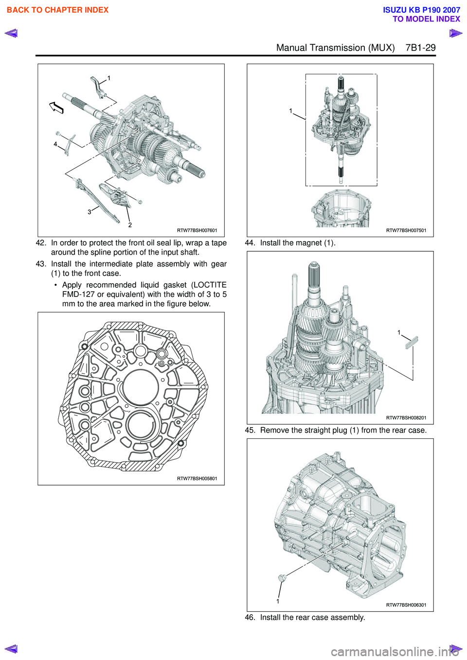
42. In order to protect the front oil seal lip, wrap a tapearound the spline portion of the input shaft.
43. Install the intermediate plate assembly with gear (1) to the front case.
• Apply recommended liquid gasket (LOCTITE FMD-127 or equivalent) with the width of 3 to 5
mm to the area marked in the figure below. 44. Install the magnet (1).
45. Remove the straight plug (1) from the rear case.
46. Install the rear case assembly.
RTW77BSH007601
1
4
3
2
RTW77BSH005801
RTW77BSH007501
1
RTW77BSH008201
1
RTW77BSH0063011
BACK TO CHAPTER INDEX
TO MODEL INDEX
ISUZU KB P190 2007
Page 4749 of 6020

7B1-30 Manual Transmission (MUX)
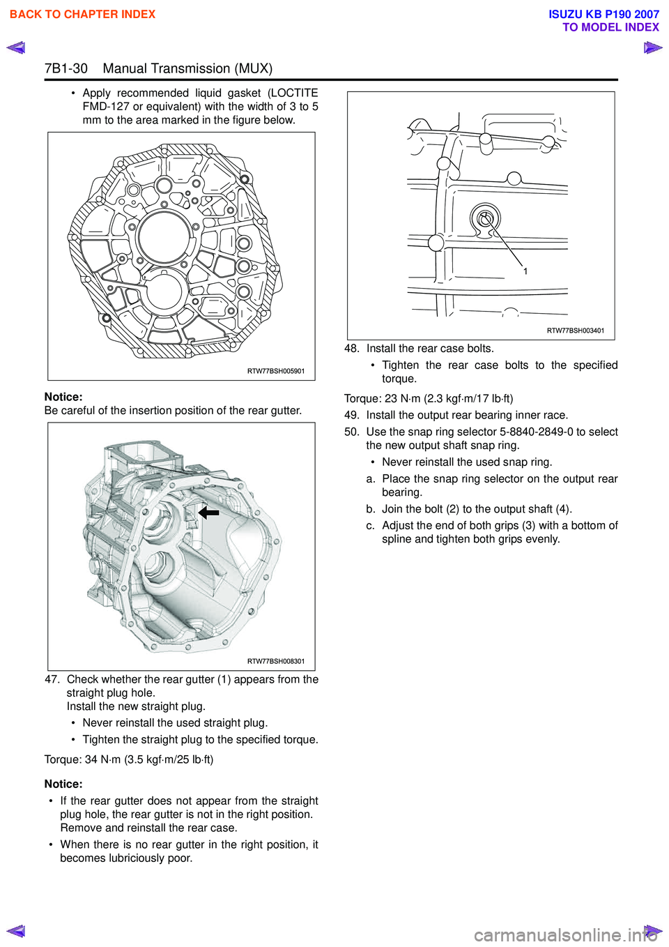
• Apply recommended liquid gasket (LOCTITEFMD-127 or equivalent) with the width of 3 to 5
mm to the area marked in the figure below.
Notice:
Be careful of the insertion position of the rear gutter.
47. Check whether the rear gutter (1) appears from the straight plug hole.
Install the new straight plug.
• Never reinstall the used straight plug.
• Tighten the straight plug to the specified torque.
Torque: 34 N ⋅m (3.5 kgf ⋅m/25 lb ⋅ft)
Notice: • If the rear gutter does not appear from the straight plug hole, the rear gutter is not in the right position.
Remove and reinstall the rear case.
• When there is no rear gutter in the right position, it becomes lubriciously poor. 48. Install the rear case bolts.
• Tighten the rear case bolts to the specifiedtorque.
Torque: 23 N ⋅m (2.3 kgf ⋅m/17 lb ⋅ft)
49. Install the output rear bearing inner race.
50. Use the snap ring selector 5-8840-2849-0 to select the new output shaft snap ring.
• Never reinstall the used snap ring.
a. Place the snap ring selector on the output rear bearing.
b. Join the bolt (2) to the output shaft (4).
c. Adjust the end of both grips (3) with a bottom of spline and tighten both grips evenly.
RTW77BSH005901
RTW77BSH008301
RTW77BSH003401
1
BACK TO CHAPTER INDEX
TO MODEL INDEX
ISUZU KB P190 2007
Page 4751 of 6020

7B1-32 Manual Transmission (MUX)
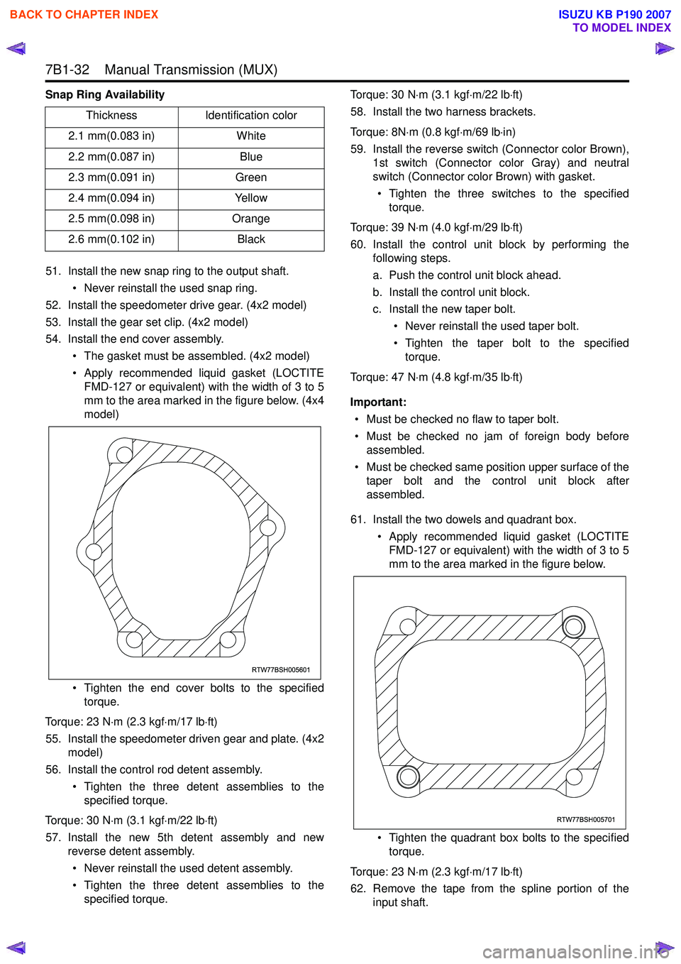
Snap Ring Availability51. Install the new snap ring to the output shaft. • Never reinstall the used snap ring.
52. Install the speedometer drive gear. (4x2 model)
53. Install the gear set clip. (4x2 model)
54. Install the end cover assembly.
• The gasket must be assembled. (4x2 model)
• Apply recommended liquid gasket (LOCTITE FMD-127 or equivalent) with the width of 3 to 5
mm to the area marked in the figure below. (4x4
model)
• Tighten the end cover bolts to the specified torque.
Torque: 23 N ⋅m (2.3 kgf ⋅m/17 lb ⋅ft)
55. Install the speedometer driven gear and plate. (4x2 model)
56. Install the control rod detent assembly.
• Tighten the three detent assemblies to thespecified torque.
Torque: 30 N ⋅m (3.1 kgf ⋅m/22 lb ⋅ft)
57. Install the new 5th detent assembly and new reverse detent assembly.
• Never reinstall the used detent assembly.
• Tighten the three detent assemblies to the specified torque. Torque: 30 N
⋅m (3.1 kgf ⋅m/22 lb ⋅ft)
58. Install the two harness brackets.
Torque: 8N ⋅m (0.8 kgf ⋅m/69 lb ⋅in)
59. Install the reverse switch (Connector color Brown), 1st switch (Connector color Gray) and neutral
switch (Connector color Brown) with gasket.
• Tighten the three switches to the specified torque.
Torque: 39 N ⋅m (4.0 kgf ⋅m/29 lb ⋅ft)
60. Install the control unit block by performing the following steps.
a. Push the control unit block ahead.
b. Install the control unit block.
c. Install the new taper bolt.
• Never reinstall the used taper bolt.
• Tighten the taper bolt to the specified torque.
Torque: 47 N ⋅m (4.8 kgf ⋅m/35 lb ⋅ft)
Important: • Must be checked no flaw to taper bolt.
• Must be checked no jam of foreign body before assembled.
• Must be checked same position upper surface of the taper bolt and the control unit block after
assembled.
61. Install the two dowels and quadrant box. • Apply recommended liquid gasket (LOCTITEFMD-127 or equivalent) with the width of 3 to 5
mm to the area marked in the figure below.
• Tighten the quadrant box bolts to the specified torque.
Torque: 23 N ⋅m (2.3 kgf ⋅m/17 lb ⋅ft)
62. Remove the tape from the spline portion of the input shaft.
Thickness
Identification color
2.1 mm(0.083 in) White
2.2 mm(0.087 in) Blue
2.3 mm(0.091 in) Green
2.4 mm(0.094 in) Yellow
2.5 mm(0.098 in) Orange
2.6 mm(0.102 in) Black
RTW77BSH005601
RTW77BSH005701
BACK TO CHAPTER INDEX
TO MODEL INDEX
ISUZU KB P190 2007
Page 4855 of 6020

TRANSFER CASE 7D-25
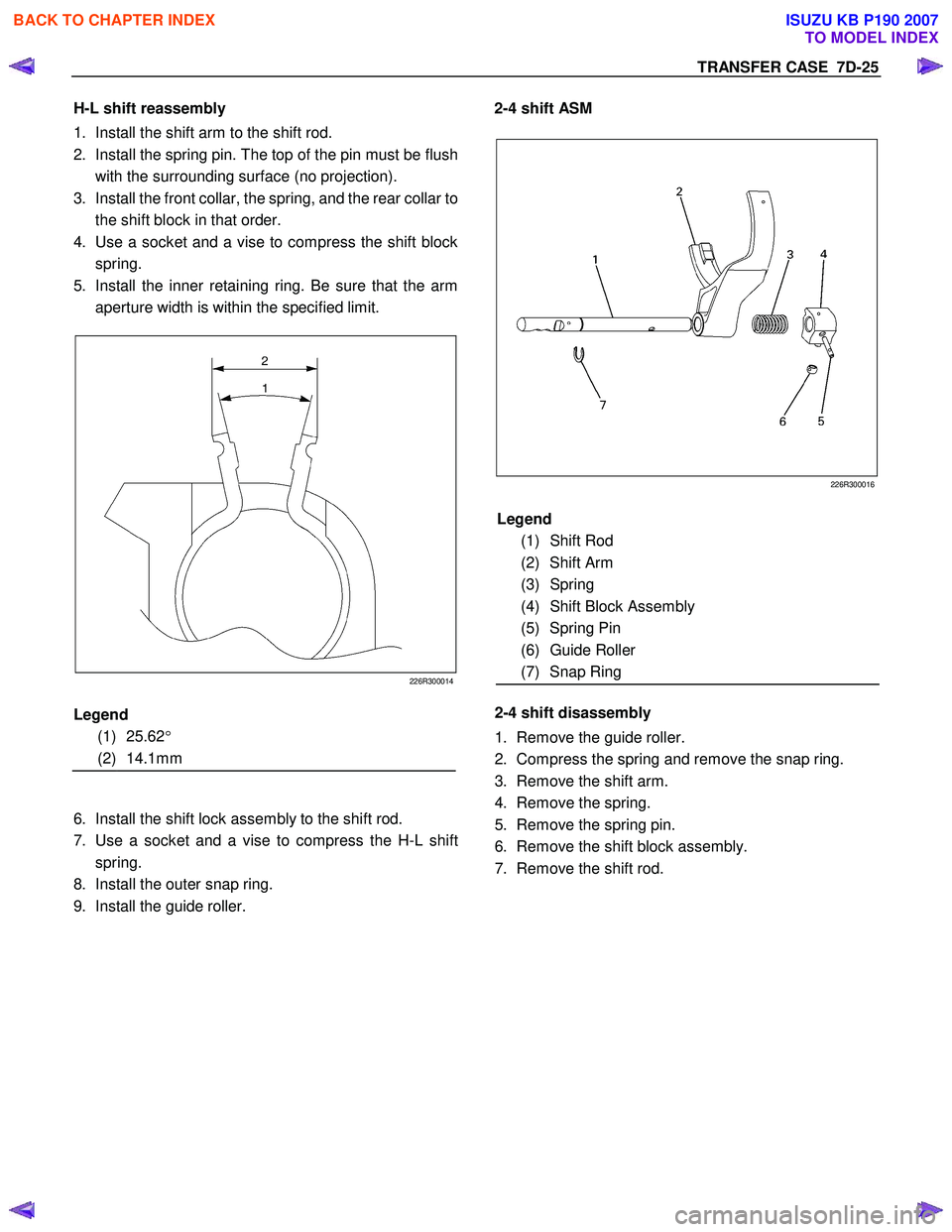
H-L shift reassembly
1. Install the shift arm to the shift rod.
2. Install the spring pin. The top of the pin must be flush
with the surrounding surface (no projection).
3. Install the front collar, the spring, and the rear collar to
the shift block in that order.
4. Use a socket and a vise to compress the shift block
spring.
5. Install the inner retaining ring. Be sure that the arm
aperture width is within the specified limit.
226R300014
6. Install the shift lock assembly to the shift rod.
7. Use a socket and a vise to compress the H-L shift
spring.
8. Install the outer snap ring.
9. Install the guide roller.
2-4 shift ASM
226R300016
2-4 shift disassembly
1. Remove the guide roller.
2. Compress the spring and remove the snap ring.
3. Remove the shift arm.
4. Remove the spring.
5. Remove the spring pin.
6. Remove the shift block assembly.
7. Remove the shift rod.
Legend
(1) 25.62 °
(2) 14.1mm Legend
(1) Shift Rod
(2) Shift Arm
(3) Spring
(4) Shift Block Assembly
(5) Spring Pin
(6) Guide Roller
(7) Snap Ring
BACK TO CHAPTER INDEX
TO MODEL INDEX
ISUZU KB P190 2007