sensor ISUZU KB P190 2007 Workshop Repair Manual
[x] Cancel search | Manufacturer: ISUZU, Model Year: 2007, Model line: KB P190, Model: ISUZU KB P190 2007Pages: 6020, PDF Size: 70.23 MB
Page 3452 of 6020
Engine Management – V6 – Diagnostics Page 6C1-2–174
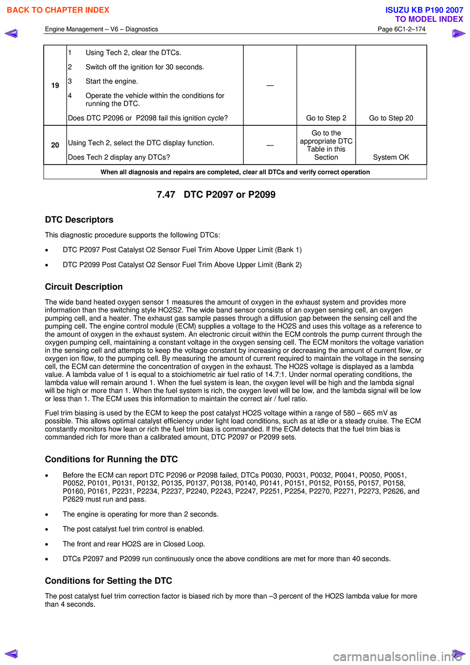
19 1 Using Tech 2, clear the DTCs.
2 Switch off the ignition for 30 seconds.
3 Start the engine.
4 Operate the vehicle within the conditions for running the DTC.
Does DTC P2096 or P2098 fail this ignition cycle? —
Go to Step 2 Go to Step 20
20 Using Tech 2, select the DTC display function.
Does Tech 2 display any DTCs? —
Go to the
appropriate DTC Table in this Section System OK
When all diagnosis and repairs are completed, clear all DTCs and verify correct operation
7.47 DTC P2097 or P2099
DTC Descriptors
This diagnostic procedure supports the following DTCs:
• DTC P2097 Post Catalyst O2 Sensor Fuel Trim Above Upper Limit (Bank 1)
• DTC P2099 Post Catalyst O2 Sensor Fuel Trim Above Upper Limit (Bank 2)
Circuit Description
The wide band heated oxygen sensor 1 measures the amount of oxygen in the exhaust system and provides more
information than the switching style HO2S2. The wide band sensor consists of an oxygen sensing cell, an oxygen
pumping cell, and a heater. The exhaust gas sample passes through a diffusion gap between the sensing cell and the
pumping cell. The engine control module (ECM) supplies a voltage to the HO2S and uses this voltage as a reference to
the amount of oxygen in the exhaust system. An electronic circuit within the ECM controls the pump current through the
oxygen pumping cell, maintaining a constant voltage in the oxygen sensing cell. The ECM monitors the voltage variation
in the sensing cell and attempts to keep the voltage constant by increasing or decreasing the amount of current flow, or
oxygen ion flow, to the pumping cell. By measuring the amount of current required to maintain the voltage in the sensing
cell, the ECM can determine the concentration of oxygen in the exhaust. The HO2S voltage is displayed as a lambda
value. A lambda value of 1 is equal to a stoichiometric air fuel ratio of 14.7:1. Under normal operating conditions, the
lambda value will remain around 1. W hen the fuel system is lean, the oxygen level will be high and the lambda signal
will be high or more than 1. W hen the fuel system is rich, the oxygen level will be low, and the lambda signal will be low
or less than 1. The ECM uses this information to maintain the correct air / fuel ratio.
Fuel trim biasing is used by the ECM to keep the post catalyst HO2S voltage within a range of 580 – 665 mV as
possible. This allows optimal catalyst efficiency under light load conditions, such as at idle or a steady cruise. The ECM
constantly monitors how lean or rich the fuel trim bias is commanded. If the ECM detects that the fuel trim bias is
commanded rich for more than a calibrated amount, DTC P2097 or P2099 sets.
Conditions for Running the DTC
• Before the ECM can report DTC P2096 or P2098 failed, DTCs P0030, P0031, P0032, P0041, P0050, P0051,
P0052, P0101, P0131, P0132, P0135, P0137, P0138, P0140, P0141, P0151, P0152, P0155, P0157, P0158,
P0160, P0161, P2231, P2234, P2237, P2240, P2243, P2247, P2251, P2254, P2270, P2271, P2273, P2626, and
P2629 must run and pass.
• The engine is operating for more than 2 seconds.
• The post catalyst fuel trim control is enabled.
• The front and rear HO2S are in Closed Loop.
• DTCs P2097 and P2099 run continuously once the above conditions are met for more than 40 seconds.
Conditions for Setting the DTC
The post catalyst fuel trim correction factor is biased rich by more than –3 percent of the HO2S lambda value for more
than 4 seconds.
BACK TO CHAPTER INDEX
TO MODEL INDEX
ISUZU KB P190 2007
Page 3453 of 6020
Engine Management – V6 – Diagnostics Page 6C1-2–175
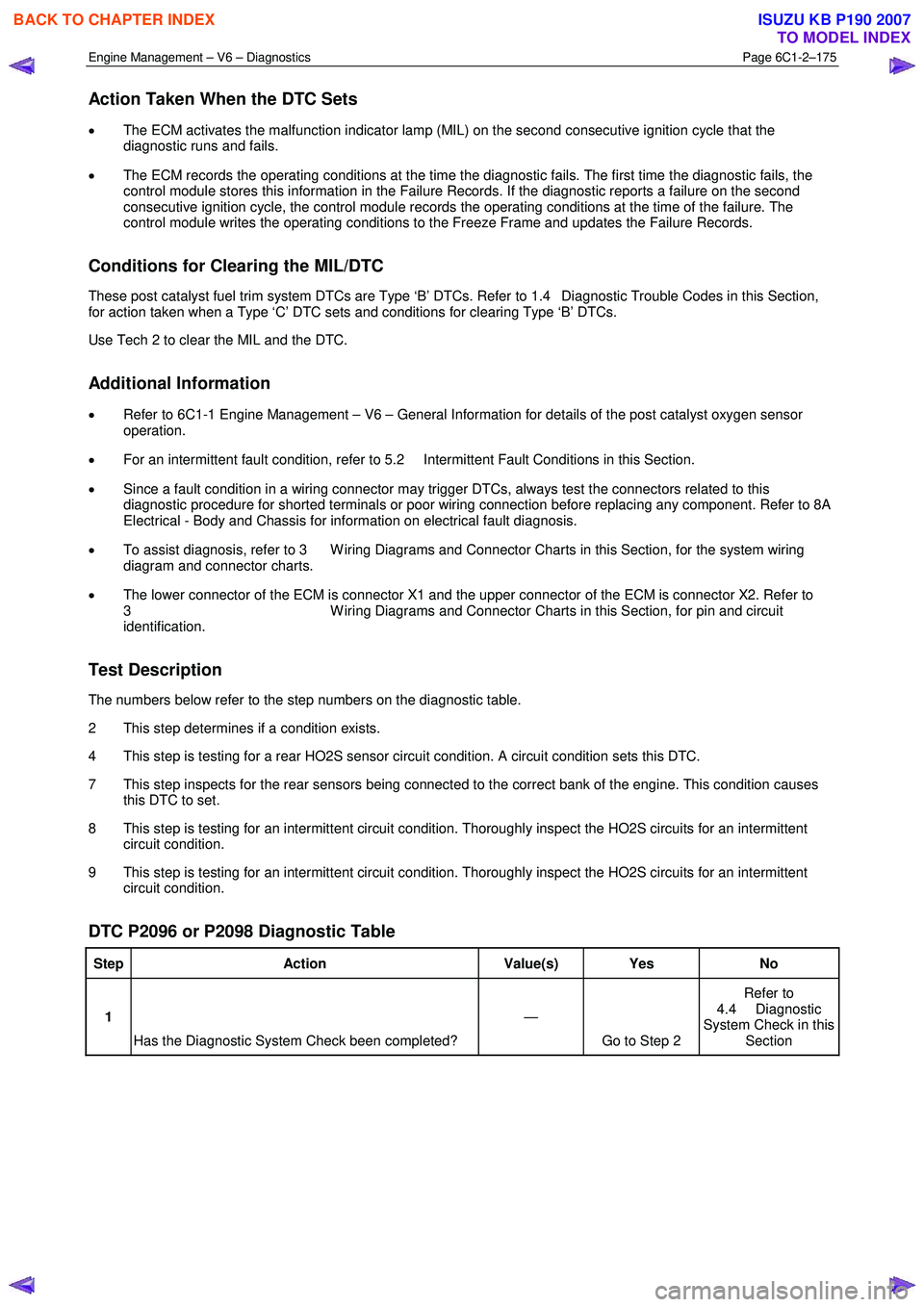
Action Taken When the DTC Sets
• The ECM activates the malfunction indicator lamp (MIL) on the second consecutive ignition cycle that the
diagnostic runs and fails.
• The ECM records the operating conditions at the time the diagnostic fails. The first time the diagnostic fails, the
control module stores this information in the Failure Records. If the diagnostic reports a failure on the second
consecutive ignition cycle, the control module records the operating conditions at the time of the failure. The
control module writes the operating conditions to the Freeze Frame and updates the Failure Records.
Conditions for Clearing the MIL/DTC
These post catalyst fuel trim system DTCs are Type ‘B’ DTCs. Refer to 1.4 Diagnostic Trouble Codes in this Section,
for action taken when a Type ‘C’ DTC sets and conditions for clearing Type ‘B’ DTCs.
Use Tech 2 to clear the MIL and the DTC.
Additional Information
• Refer to 6C1-1 Engine Management – V6 – General Information for details of the post catalyst oxygen sensor
operation.
• For an intermittent fault condition, refer to 5.2 Intermittent Fault Conditions in this Section.
• Since a fault condition in a wiring connector may trigger DTCs, always test the connectors related to this
diagnostic procedure for shorted terminals or poor wiring connection before replacing any component. Refer to 8A
Electrical - Body and Chassis for information on electrical fault diagnosis.
• To assist diagnosis, refer to 3 W iring Diagrams and Connector Charts in this Section, for the system wiring
diagram and connector charts.
• The lower connector of the ECM is connector X1 and the upper connector of the ECM is connector X2. Refer to
3 W iring Diagrams and Connector Charts in this Section, for pin and circuit
identification.
Test Description
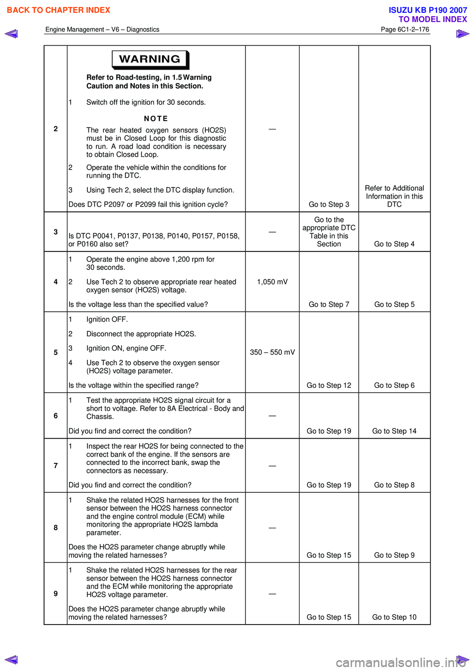
The numbers below refer to the step numbers on the diagnostic table.
2 This step determines if a condition exists.
4 This step is testing for a rear HO2S sensor circuit condition. A circuit condition sets this DTC.
7 This step inspects for the rear sensors being connected to the correct bank of the engine. This condition causes this DTC to set.
8 This step is testing for an intermittent circuit condition. Thoroughly inspect the HO2S circuits for an intermittent circuit condition.
9 This step is testing for an intermittent circuit condition. Thoroughly inspect the HO2S circuits for an intermittent circuit condition.
DTC P2096 or P2098 Diagnostic Table
Step Action Value(s) Yes No
1
Has the Diagnostic System Check been completed? —
Go to Step 2 Refer to
4.4 Diagnostic
System Check in this Section
BACK TO CHAPTER INDEX
TO MODEL INDEX
ISUZU KB P190 2007
Page 3454 of 6020
Engine Management – V6 – Diagnostics Page 6C1-2–176
2 Refer to Road-testing, in 1.5 Warning
Caution and Notes in this Section.
1 Switch off the ignition for 30 seconds.
NOTE
The rear heated oxygen sensors (HO2S)
must be in Closed Loop for this diagnostic
to run. A road load condition is necessary
to obtain Closed Loop.
2 Operate the vehicle within the conditions for running the DTC.
3 Using Tech 2, select the DTC display function.
Does DTC P2097 or P2099 fail this ignition cycle? —
Go to Step 3 Refer to Additional
Information in this DTC
3 Is DTC P0041, P0137, P0138, P0140, P0157, P0158,
or P0160 also set? —
Go to the
appropriate DTC Table in this Section Go to Step 4
4 1 Operate the engine above 1,200 rpm for
30 seconds.
2 Use Tech 2 to observe appropriate rear heated oxygen sensor (HO2S) voltage.
Is the voltage less than the specified value? 1,050 mV
Go to Step 7 Go to Step 5
5 1 Ignition OFF.
2 Disconnect the appropriate HO2S.
3 Ignition ON, engine OFF.
4 Use Tech 2 to observe the oxygen sensor (HO2S) voltage parameter.
Is the voltage within the specified range? 350 – 550 mV
Go to Step 12 Go to Step 6
6 1 Test the appropriate HO2S signal circuit for a
short to voltage. Refer to 8A Electrical - Body and
Chassis.
Did you find and correct the condition? —
Go to Step 19 Go to Step 14
7 1 Inspect the rear HO2S for being connected to the
correct bank of the engine. If the sensors are
connected to the incorrect bank, swap the
connectors as necessary.
Did you find and correct the condition? —
Go to Step 19 Go to Step 8
8 1 Shake the related HO2S harnesses for the front
sensor between the HO2S harness connector
and the engine control module (ECM) while
monitoring the appropriate HO2S lambda
parameter.
Does the HO2S parameter change abruptly while
moving the related harnesses? —
Go to Step 15 Go to Step 9
9 1 Shake the related HO2S harnesses for the rear
sensor between the HO2S harness connector
and the ECM while monitoring the appropriate
HO2S voltage parameter.
Does the HO2S parameter change abruptly while
moving the related harnesses? —
Go to Step 15 Go to Step 10
BACK TO CHAPTER INDEX
TO MODEL INDEX
ISUZU KB P190 2007
Page 3455 of 6020
Engine Management – V6 – Diagnostics Page 6C1-2–177
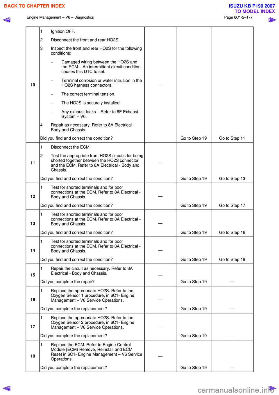
10 1 Ignition OFF.
2 Disconnect the front and rear HO2S.
3 Inspect the front and rear HO2S for the following conditions:
− Damaged wiring between the HO2S and
the ECM – An intermittent circuit condition
causes this DTC to set.
− Terminal corrosion or water intrusion in the
HO2S harness connectors.
− The correct terminal tension.
− The HO2S is securely installed.
− Any exhaust leaks – Refer to 6F Exhaust
System – V6.
4 Repair as necessary. Refer to 8A Electrical - Body and Chassis.
Did you find and correct the condition? —
Go to Step 19 Go to Step 11
11 1 Disconnect the ECM.
2 Test the appropriate front HO2S circuits for being shorted together between the HO2S connector
and the ECM. Refer to 8A Electrical - Body and
Chassis.
Did you find and correct the condition? —
Go to Step 19 Go to Step 13
12 1 Test for shorted terminals and for poor
connections at the ECM. Refer to 8A Electrical -
Body and Chassis.
Did you find and correct the condition? —
Go to Step 19 Go to Step 17
13 1 Test for shorted terminals and for poor
connections at the ECM. Refer to 8A Electrical -
Body and Chassis.
Did you find and correct the condition? —
Go to Step 19 Go to Step 16
14 1 Test for shorted terminals and for poor
connections at the ECM. Refer to 8A Electrical -
Body and Chassis.
Did you find and correct the condition? —
Go to Step 19 Go to Step 18
15 1 Repair the circuit as necessary. Refer to 8A
Electrical - Body and Chassis.
Did you complete the repair? —
Go to Step 19 —
16 1 Replace the appropriate HO2S. Refer to the
Oxygen Sensor 1 procedure, in 6C1- Engine
Management – V6 Service Operations.
Did you complete the replacement? —
Go to Step 19 —
17 1 Replace the appropriate HO2S. Refer to the
Oxygen Sensor 2 procedure, in 6C1- Engine
Management – V6 Service Operations.
Did you complete the replacement? —
Go to Step 19 —
18 1 Replace the ECM. Refer to Engine Control
Module (ECM) Remove, Reinstall and ECM
Reset in 6C1- Engine Management – V6 Service
Operations.
Did you complete the replacement? —
Go to Step 19 —
BACK TO CHAPTER INDEX
TO MODEL INDEX
ISUZU KB P190 2007
Page 3456 of 6020
Engine Management – V6 – Diagnostics Page 6C1-2–178
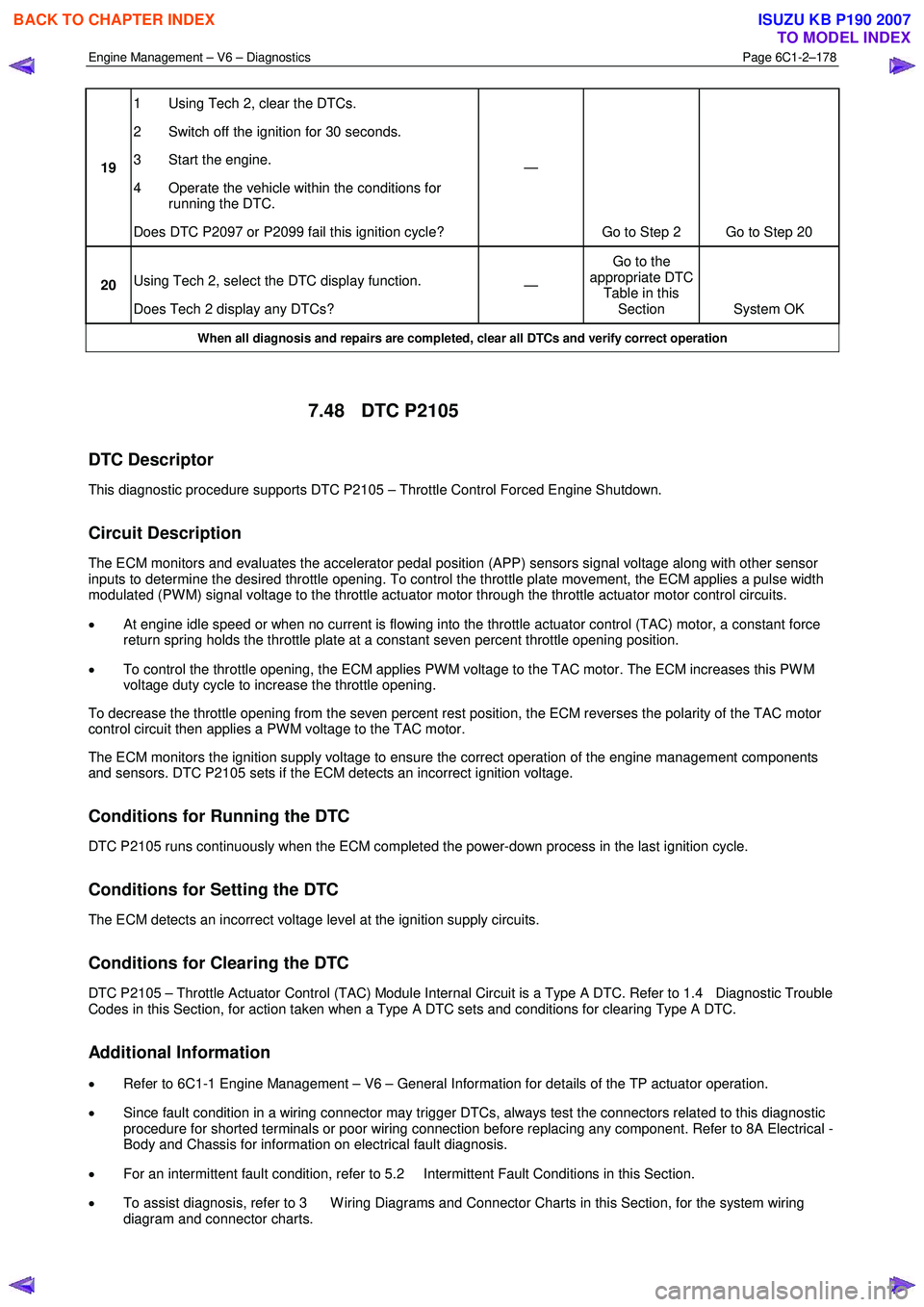
19 1 Using Tech 2, clear the DTCs.
2 Switch off the ignition for 30 seconds.
3 Start the engine.
4 Operate the vehicle within the conditions for running the DTC.
Does DTC P2097 or P2099 fail this ignition cycle? —
Go to Step 2 Go to Step 20
20 Using Tech 2, select the DTC display function.
Does Tech 2 display any DTCs? —
Go to the
appropriate DTC Table in this Section System OK
When all diagnosis and repairs are completed, clear all DTCs and verify correct operation
7.48 DTC P2105
DTC Descriptor
This diagnostic procedure supports DTC P2105 – Throttle Control Forced Engine Shutdown.
Circuit Description
The ECM monitors and evaluates the accelerator pedal position (APP) sensors signal voltage along with other sensor
inputs to determine the desired throttle opening. To control the throttle plate movement, the ECM applies a pulse width
modulated (PW M) signal voltage to the throttle actuator motor through the throttle actuator motor control circuits.
• At engine idle speed or when no current is flowing into the throttle actuator control (TAC) motor, a constant force
return spring holds the throttle plate at a constant seven percent throttle opening position.
• To control the throttle opening, the ECM applies PW M voltage to the TAC motor. The ECM increases this PW M
voltage duty cycle to increase the throttle opening.
To decrease the throttle opening from the seven percent rest position, the ECM reverses the polarity of the TAC motor
control circuit then applies a PW M voltage to the TAC motor.
The ECM monitors the ignition supply voltage to ensure the correct operation of the engine management components
and sensors. DTC P2105 sets if the ECM detects an incorrect ignition voltage.
Conditions for Running the DTC
DTC P2105 runs continuously when the ECM completed the power-down process in the last ignition cycle.
Conditions for Setting the DTC
The ECM detects an incorrect voltage level at the ignition supply circuits.
Conditions for Clearing the DTC
DTC P2105 – Throttle Actuator Control (TAC) Module Internal Circuit is a Type A DTC. Refer to 1.4 Diagnostic Trouble
Codes in this Section, for action taken when a Type A DTC sets and conditions for clearing Type A DTC.
Additional Information
• Refer to 6C1-1 Engine Management – V6 – General Information for details of the TP actuator operation.
• Since fault condition in a wiring connector may trigger DTCs, always test the connectors related to this diagnostic
procedure for shorted terminals or poor wiring connection before replacing any component. Refer to 8A Electrical -
Body and Chassis for information on electrical fault diagnosis.
• For an intermittent fault condition, refer to 5.2 Intermittent Fault Conditions in this Section.
• To assist diagnosis, refer to 3 W iring Diagrams and Connector Charts in this Section, for the system wiring
diagram and connector charts.
BACK TO CHAPTER INDEX
TO MODEL INDEX
ISUZU KB P190 2007
Page 3457 of 6020
Engine Management – V6 – Diagnostics Page 6C1-2–179
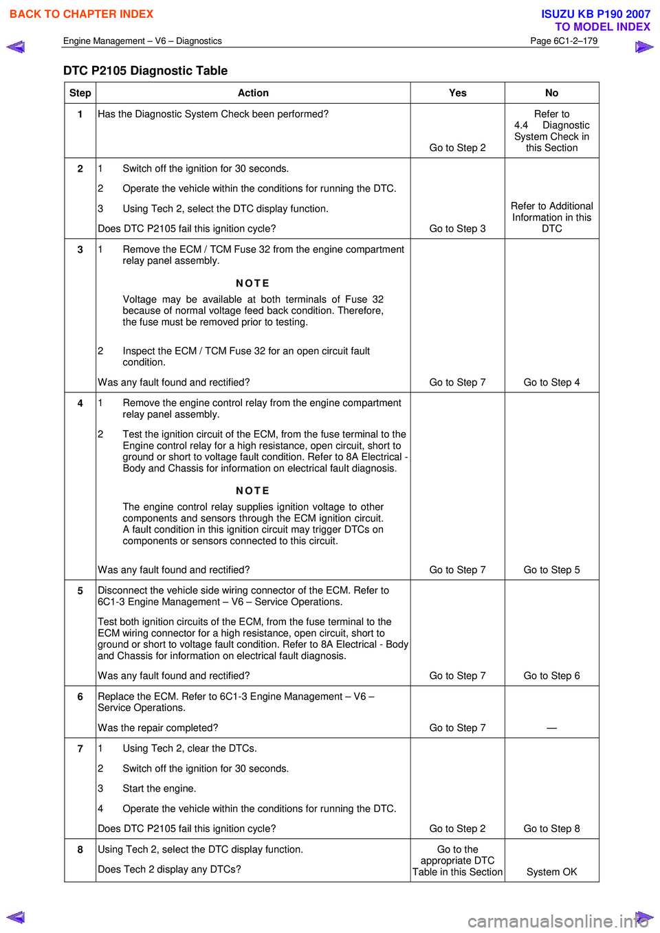
DTC P2105 Diagnostic Table
Step Action Yes No
1 Has the Diagnostic System Check been performed?
Go to Step 2 Refer to
4.4 Diagnostic
System Check in this Section
2 1 Switch off the ignition for 30 seconds.
2 Operate the vehicle within the conditions for running the DTC.
3 Using Tech 2, select the DTC display function.
Does DTC P2105 fail this ignition cycle? Go to Step 3 Refer to Additional
Information in this DTC
3 1 Remove the ECM / TCM Fuse 32 from the engine compartment
relay panel assembly.
NOTE
Voltage may be available at both terminals of Fuse 32
because of normal voltage feed back condition. Therefore,
the fuse must be removed prior to testing.
2 Inspect the ECM / TCM Fuse 32 for an open circuit fault condition.
W as any fault found and rectified? Go to Step 7 Go to Step 4
4 1 Remove the engine control relay from the engine compartment
relay panel assembly.
2 Test the ignition circuit of the ECM, from the fuse terminal to the Engine control relay for a high resistance, open circuit, short to
ground or short to voltage fault condition. Refer to 8A Electrical -
Body and Chassis for information on electrical fault diagnosis.
NOTE
The engine control relay supplies ignition voltage to other
components and sensors through the ECM ignition circuit.
A fault condition in this ignition circuit may trigger DTCs on
components or sensors connected to this circuit.
W as any fault found and rectified? Go to Step 7 Go to Step 5
5 Disconnect the vehicle side wiring connector of the ECM. Refer to
6C1-3 Engine Management – V6 – Service Operations.
Test both ignition circuits of the ECM, from the fuse terminal to the
ECM wiring connector for a high resistance, open circuit, short to
ground or short to voltage fault condition. Refer to 8A Electrical - Body
and Chassis for information on electrical fault diagnosis.
W as any fault found and rectified? Go to Step 7 Go to Step 6
6 Replace the ECM. Refer to 6C1-3 Engine Management – V6 –
Service Operations.
W as the repair completed? Go to Step 7 —
7 1 Using Tech 2, clear the DTCs.
2 Switch off the ignition for 30 seconds.
3 Start the engine.
4 Operate the vehicle within the conditions for running the DTC.
Does DTC P2105 fail this ignition cycle? Go to Step 2 Go to Step 8
8 Using Tech 2, select the DTC display function.
Does Tech 2 display any DTCs? Go to the
appropriate DTC
Table in this Section System OK
BACK TO CHAPTER INDEX
TO MODEL INDEX
ISUZU KB P190 2007
Page 3458 of 6020
Engine Management – V6 – Diagnostics Page 6C1-2–180
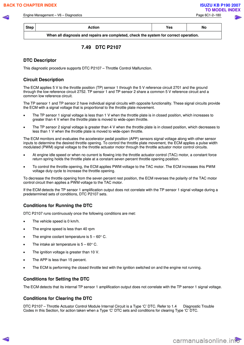
Step Action Yes
No
When all diagnosis and repairs are completed, check the system for correct operation.
7.49 DTC P2107
DTC Descriptor
This diagnostic procedure supports DTC P2107 – Throttle Control Malfunction.
Circuit Description
The ECM applies 5 V to the throttle position (TP) sensor 1 through the 5 V reference circuit 2701 and the ground
through the low reference circuit 2752. TP sensor 1 and TP sensor 2 share a common 5 V reference circuit and a
common low reference circuit.
The TP sensor 1 and TP sensor 2 have individual signal circuits with opposite functionality. These signal circuits provide
the ECM with a signal voltage that is proportional to the throttle plate movement.
• The TP sensor 1 signal voltage is less than 1 V when the throttle plate is in closed position, which increases to
greater than 4 V when the throttle plate is moved to wide-open throttle.
• The TP sensor 2 signal voltage is greater than 4 V when the throttle plate is in closed position, which decreases to
less than 1 V when the throttle plate is moved to wide-open throttle.
The ECM monitors and evaluates the accelerator pedal position (APP) sensors signal voltage along with other sensor
inputs to determine the desired throttle opening. To control the throttle plate movement, the ECM applies a pulse width
modulated (PW M) signal voltage to the throttle actuator motor through the throttle actuator motor control circuits.
• At engine idle speed or when no current is flowing into the throttle actuator control (TAC) motor, a constant force
return spring holds the throttle plate at a constant seven percent throttle opening position.
• To control the throttle opening, the ECM applies PW M voltage to the TAC motor. The ECM increases this PW M
voltage duty cycle to increase the throttle opening.
To decrease the throttle opening from the seven percent rest position, the ECM reverses the polarity of the TAC motor
control circuit then applies a PW M voltage to the TAC motor.
If the ECM detects the TP sensor 1 amplification output does not correlate with the TP sensor 1 signal voltage during a
predetermined sets of conditions, DTC P2107 sets.
Conditions for Running the DTC
DTC P2107 runs continuously once the following conditions are met:
• The vehicle speed is 0 km/h.
• The engine speed is less than 40 rpm
• The engine coolant temperature is 5 – 60 ° C.
• The intake air temperature is 5 – 60 ° C.
• The ignition voltage is greater than 10 V.
• The APP is less than 15 percent.
• The ECM is performing the closed throttle test with the ignition switched on and the engine not running.
Conditions for Setting the DTC
The ECM detects that its internal TP sensor 1 amplification output does not correlate with the TP sensor 1 signal voltage.
Conditions for Clearing the DTC
DTC P2107 – Throttle Actuator Control Module Internal Circuit is a Type ‘C’ DTC. Refer to 1.4 Diagnostic Trouble
Codes in this Section, for action taken when a Type ‘C’ DTC sets and conditions for clearing Type ‘C’ DTC.
BACK TO CHAPTER INDEX
TO MODEL INDEX
ISUZU KB P190 2007
Page 3459 of 6020
Engine Management – V6 – Diagnostics Page 6C1-2–181
Additional Information
• Refer to 6C1-1 Engine Management – V6 – General Information for details of the TP sensor operation.
• For an intermittent fault condition, refer to 5.2 Intermittent Fault Conditions in this Section.
• Since fault condition in a wiring connector may trigger DTCs, always test the connectors related to this diagnostic
procedure for shorted terminals or poor wiring connection before replacing any component. Refer to 8A Electrical -
Body and Chassis for information on electrical fault diagnosis.
• To assist diagnosis, refer to 3 W iring Diagrams and Connector Charts in this Section, for the system wiring
diagram and connector charts.
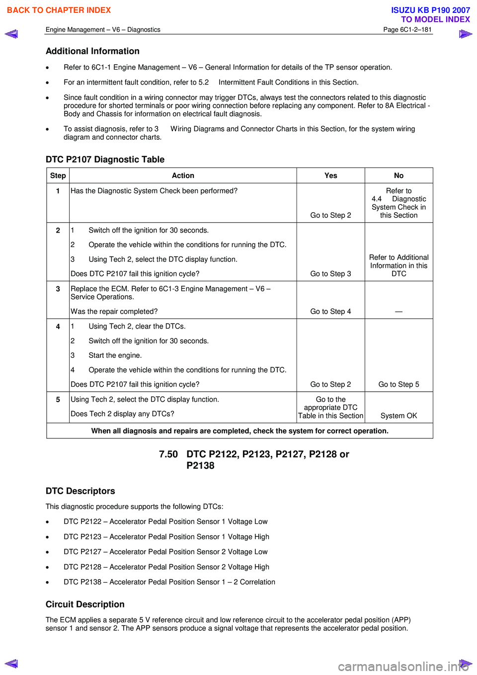
DTC P2107 Diagnostic Table
Step Action Yes No
1 Has the Diagnostic System Check been performed?
Go to Step 2 Refer to
4.4 Diagnostic
System Check in this Section
2 1 Switch off the ignition for 30 seconds.
2 Operate the vehicle within the conditions for running the DTC.
3 Using Tech 2, select the DTC display function.
Does DTC P2107 fail this ignition cycle? Go to Step 3 Refer to Additional
Information in this DTC
3 Replace the ECM. Refer to 6C1-3 Engine Management – V6 –
Service Operations.
W as the repair completed? Go to Step 4 —
4 1 Using Tech 2, clear the DTCs.
2 Switch off the ignition for 30 seconds.
3 Start the engine.
4 Operate the vehicle within the conditions for running the DTC.
Does DTC P2107 fail this ignition cycle? Go to Step 2 Go to Step 5
5 Using Tech 2, select the DTC display function.
Does Tech 2 display any DTCs? Go to the
appropriate DTC
Table in this Section System OK
When all diagnosis and repairs are completed, check the system for correct operation.
7.50 DTC P2122, P2123, P2127, P2128 or
P2138
DTC Descriptors
This diagnostic procedure supports the following DTCs:
• DTC P2122 – Accelerator Pedal Position Sensor 1 Voltage Low
• DTC P2123 – Accelerator Pedal Position Sensor 1 Voltage High
• DTC P2127 – Accelerator Pedal Position Sensor 2 Voltage Low
• DTC P2128 – Accelerator Pedal Position Sensor 2 Voltage High
• DTC P2138 – Accelerator Pedal Position Sensor 1 – 2 Correlation
Circuit Description
The ECM applies a separate 5 V reference circuit and low reference circuit to the accelerator pedal position (APP)
sensor 1 and sensor 2. The APP sensors produce a signal voltage that represents the accelerator pedal position.
BACK TO CHAPTER INDEX
TO MODEL INDEX
ISUZU KB P190 2007
Page 3460 of 6020
Engine Management – V6 – Diagnostics Page 6C1-2–182
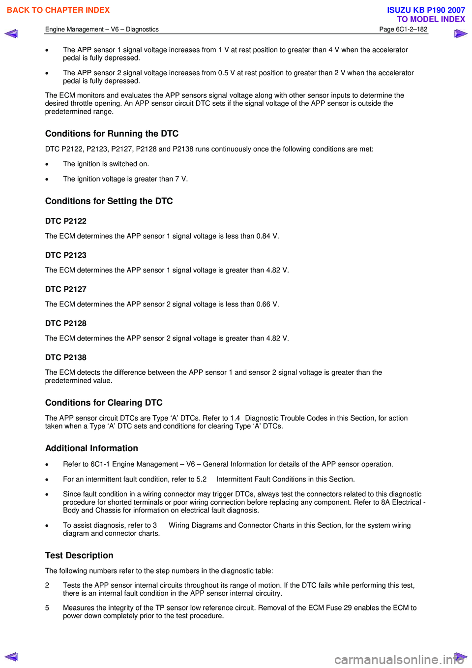
• The APP sensor 1 signal voltage increases from 1 V at rest position to greater than 4 V when the accelerator
pedal is fully depressed.
• The APP sensor 2 signal voltage increases from 0.5 V at rest position to greater than 2 V when the accelerator
pedal is fully depressed.
The ECM monitors and evaluates the APP sensors signal voltage along with other sensor inputs to determine the
desired throttle opening. An APP sensor circuit DTC sets if the signal voltage of the APP sensor is outside the
predetermined range.
Conditions for Running the DTC
DTC P2122, P2123, P2127, P2128 and P2138 runs continuously once the following conditions are met:
• The ignition is switched on.
• The ignition voltage is greater than 7 V.
Conditions for Setting the DTC
DTC P2122
The ECM determines the APP sensor 1 signal voltage is less than 0.84 V.
DTC P2123
The ECM determines the APP sensor 1 signal voltage is greater than 4.82 V.
DTC P2127
The ECM determines the APP sensor 2 signal voltage is less than 0.66 V.
DTC P2128
The ECM determines the APP sensor 2 signal voltage is greater than 4.82 V.
DTC P2138
The ECM detects the difference between the APP sensor 1 and sensor 2 signal voltage is greater than the
predetermined value.
Conditions for Clearing DTC
The APP sensor circuit DTCs are Type ‘A’ DTCs. Refer to 1.4 Diagnostic Trouble Codes in this Section, for action
taken when a Type ‘A’ DTC sets and conditions for clearing Type ‘A’ DTCs.
Additional Information
• Refer to 6C1-1 Engine Management – V6 – General Information for details of the APP sensor operation.
• For an intermittent fault condition, refer to 5.2 Intermittent Fault Conditions in this Section.
• Since fault condition in a wiring connector may trigger DTCs, always test the connectors related to this diagnostic
procedure for shorted terminals or poor wiring connection before replacing any component. Refer to 8A Electrical -
Body and Chassis for information on electrical fault diagnosis.
• To assist diagnosis, refer to 3 W iring Diagrams and Connector Charts in this Section, for the system wiring
diagram and connector charts.
Test Description
The following numbers refer to the step numbers in the diagnostic table:
2 Tests the APP sensor internal circuits throughout its range of motion. If the DTC fails while performing this test, there is an internal fault condition in the APP sensor internal circuitry.
5 Measures the integrity of the TP sensor low reference circuit. Removal of the ECM Fuse 29 enables the ECM to power down completely prior to the test procedure.
BACK TO CHAPTER INDEX
TO MODEL INDEX
ISUZU KB P190 2007
Page 3461 of 6020
Engine Management – V6 – Diagnostics Page 6C1-2–183
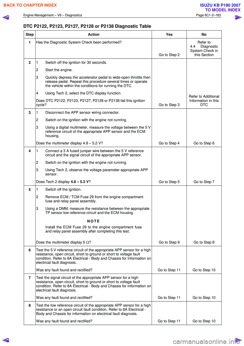
DTC P2122, P2123, P2127, P2128 or P2138 Diagnostic Table
Step Action Yes No
1 Has the Diagnostic System Check been performed?
Go to Step 2 Refer to
4.4 Diagnostic
System Check in this Section
2 1 Switch off the ignition for 30 seconds.
2 Start the engine.
3 Quickly depress the accelerator pedal to wide-open throttle then release pedal. Repeat this procedure several times or operate
the vehicle within the conditions for running the DTC.
4 Using Tech 2, select the DTC display function.
Does DTC P2122, P2123, P2127, P2128 or P2138 fail this ignition
cycle? Go to Step 3 Refer to Additional
Information in this DTC
3 1 Disconnect the APP sensor wiring connector.
2 Switch on the ignition with the engine not running.
3 Using a digital multimeter, measure the voltage between the 5 V reference circuit of the appropriate APP sensor and the ECM
housing.
Does the multimeter display 4.8 – 5.2 V? Go to Step 4 Go to Step 6
4 1 Connect a 3 A fused jumper wire between the 5 V reference
circuit and the signal circuit of the appropriate APP sensor.
2 Switch on the ignition with the engine not running.
3 Using Tech 2, observe the voltage parameter appropriate APP sensor.
Does Tech 2 display 4.8 – 5.2 V ?
Go to Step 5 Go to Step 7
5 1 Switch off the ignition.
2 Remove ECM / TCM Fuse 29 from the engine compartment fuse and relay panel assembly.
3 Using a DMM, measure the resistance between the appropriate TP sensor low reference circuit and the ECM housing.
NOTE
Install the ECM Fuse 29 to the engine compartment fuse
and relay panel assembly after completing this test.
Does the multimeter display 5 Ω? Go to Step 9 Go to Step 8
6 Test the 5 V reference circuit of the appropriate APP sensor for a high
resistance, open circuit, short to ground or short to voltage fault
condition. Refer to 8A Electrical - Body and Chassis for information on
electrical fault diagnosis.
W as any fault found and rectified? Go to Step 11 Go to Step 10
7 Test the signal circuit of the appropriate APP sensor for a high
resistance, open circuit, short to ground or short to voltage fault
condition. Refer to 8A Electrical - Body and Chassis for information on
electrical fault diagnosis.
W as any fault found and rectified? Go to Step 11 Go to Step 10
8 Test the low reference circuit of the appropriate APP sensor for a high
resistance or an open circuit fault condition. Refer to 8A Electrical -
Body and Chassis for information on electrical fault diagnosis.
W as any fault found and rectified? Go to Step 11 Go to Step 10
BACK TO CHAPTER INDEX
TO MODEL INDEX
ISUZU KB P190 2007