MOTOR ISUZU KB P190 2007 Workshop Repair Manual
[x] Cancel search | Manufacturer: ISUZU, Model Year: 2007, Model line: KB P190, Model: ISUZU KB P190 2007Pages: 6020, PDF Size: 70.23 MB
Page 35 of 6020
HEATER AND AIR CONDITIONING 1-1
SECTION 1
HEATER AND AIR CONDITIONING
TABLE OF CONTENTS
PAGE
General Description ........................................................................................................ 1- 3
Main Data and Specifications ......................................................................................... 1- 21
Special Parts Fixing Nuts and Bolts .............................................................................. 1- 23
On-Vehicle Service .......................................................................................................... 1- 30
Precautions For Replacement or repair of air conditioning parts .......................... 1- 30
Condenser...................................................................................................................... .. 1- 40
Removal and Installation (4JH1-TC, 4JJ1-TC Standard Output)............................. 1- 40
Removal and Installation (4JJ1-TC High Output, 4JK1-TC High Output, 4JA1-T) ........................................ 1- 41
Removal and Installation (C24SE) ............................................................................. 1- 42
Condenser Fan Motor ..................................................................................................... 1- 43 Removal and Installation............................................................................................ 1- 43
Receiver/drier ................................................................................................................. . 1- 44
Removal and Installation............................................................................................ 1- 44
Compressor ..................................................................................................................... 1- 45
Removal and Installation (4JA1-T, 4JH1-TC) ............................................................ 1- 45
Removal and Installation (4JJ1-TC Standard Output, 4JJ1-TC High Output, 4JK1-TC High Output) ......... 1- 47
Removal and Installation (C24SE) ............................................................................. 1- 49
Disassembly ................................................................................................................ 1- 55
Reassembly ................................................................................................................. 1- 57
Heater Unit .................................................................................................................... ... 1- 59
Removal and Installation............................................................................................ 1- 59
Disassembly and Reassembly................................................................................... 1- 61
Vent Unit (Without Heater) ............................................................................................. 1- 62 Removal and Installation............................................................................................ 1- 62
Disassembly and Reassembly................................................................................... 1- 64
TO MODEL INDEX
BACK TO MAIN INDEX
ISUZU KB P190 2007
Page 37 of 6020
HEATER AND AIR CONDITIONING 1-3
GENERAL DESCRIPTION
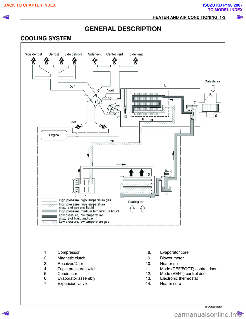
COOLING SYSTEM
1.
Compressor 8.
Evaporator core
2.
Magnetic clutch 9.
Blower motor
3.
Receiver/Drier 10.
Heater unit
4.
Triple pressure switch 11.
Mode (DEF/FOOT) control door
5.
Condenser 12.
Mode (VENT) control door
6.
Evaporator assembly 13.
Electronic thermostat
7.
Expansion valve 14.
Heater core
RTW 610LF000101
BACK TO CHAPTER INDEX
TO MODEL INDEX
ISUZU KB P190 2007
Page 56 of 6020

1-22 HEATER AND AIR CONDITIONING
RECEIVER/DRIER
Capacity cc (cu in)
kPa (kg/cm
2/psi)
kPa (kg/cm2/psi)
kPa (kg/cm
2/psi)
kPa (kg/cm2/psi) 250 (15.3)
Assembly includes sight glass and pressure sensitive device
(Dual pressure switch) • Low pressure control
OFF: 177 ±26 (1.8 ±0.25/26 ±4)
ON: 186 ±30 (1.9 ±0.3/27 ±4)
• High pressure control
OFF: 2746 ±196 (28 ±2/398 ±28)
ON: 588 ±196 (6 ±2/85 ±28)
kPa (kg/cm
2/psi)
kPa (kg/cm2/psi)
kPa (kg/cm
2/psi)
kPa (kg/cm2/psi)
kPa (kg/cm
2/psi)
kPa (kg/cm2/psi)
ELECTRIC FAN
Fan Dia
Motor Power (w)
REFRIGERANT
Type
Capacity kg (lbs)
IDLE SPEED-UP CONTROL
(Triple pressure switch) • Low pressure control
OFF: 177 ±26 (1.8 ±0.25/26 ±4)
ON: 186 ±30 (1.9 ±0.3/27 ±4)
• Medium pressure control
OFF: 1128 ±118 (11.5 ±1.2/164 ±17)
ON: 1521 ±88 (15.5 ±0.9/220 ±13)
• High pressure control
OFF: 2746 ±196 (28 ±2/398 ±28)
ON: 588 ±196 (6 ±2/85 ±28)
∅250
90
HFC-134a
• 4JA1-T, 4JH1-TC, C24SE
0.72 (1.59)
• 4JJ1-TC (Standard Output),
4JJ1-TC (High Output), 4JK1-TC (High Output)
0.65 (1.43)
Idle speed controlled by solenoid switch (4JA1-T only)
BACK TO CHAPTER INDEX
TO MODEL INDEX
ISUZU KB P190 2007
Page 77 of 6020
HEATER AND AIR CONDITIONING 1-43
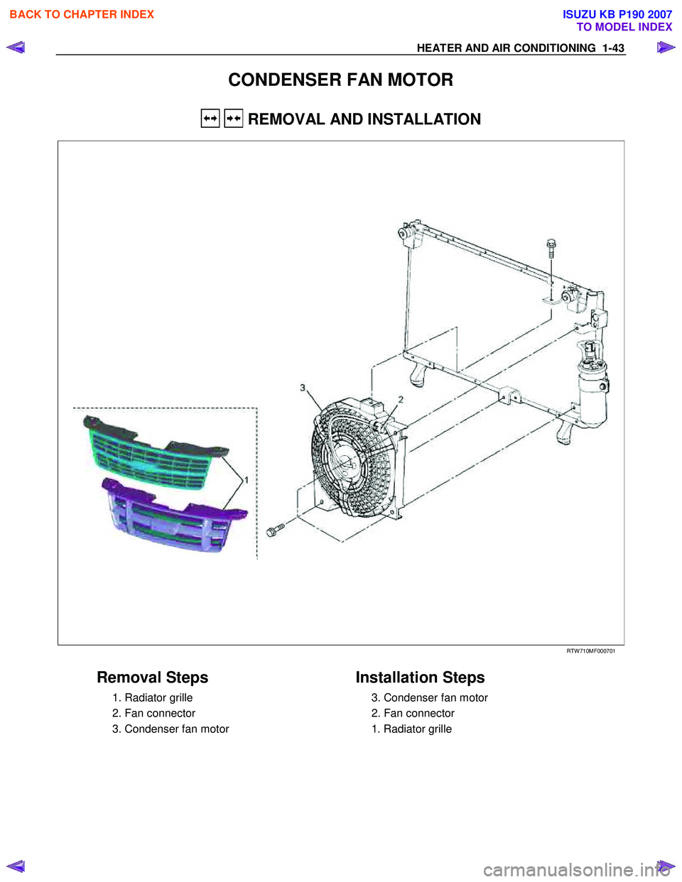
CONDENSER FAN MOTOR
REMOVAL AND INSTALLATION
RTW 710MF000701
Removal Steps
1. Radiator grille
2. Fan connector
3. Condenser fan motor
Installation Steps
3. Condenser fan motor
2. Fan connector
1. Radiator grille
BACK TO CHAPTER INDEX
TO MODEL INDEX
ISUZU KB P190 2007
Page 104 of 6020

1-70 HEATER AND AIR CONDITIONING
BLOWER UNIT ASSEMBLY
REMOVAL AND INSTALLATION
This illustration is based on RHD model
RTW 710LF001801
Removal Steps
1. Control cable
2. Instrument panel assembly and cross
beam
3. Electronic thermostat connector
4. Evaporator or duct
5. Resistor connector
6. Blower motor connector
7. Blower unit assembly or intake box assembly
Installation Steps
7. Blower unit assembly or intake box
assembly
6. Blower motor connector
5. Resistor connector
4. Evaporator or duct
3. Electronic thermostat connector
2. Instrument panel assembly and cross
beam
1. Control cable
BACK TO CHAPTER INDEX
TO MODEL INDEX
ISUZU KB P190 2007
Page 106 of 6020
1-72 HEATER AND AIR CONDITIONING
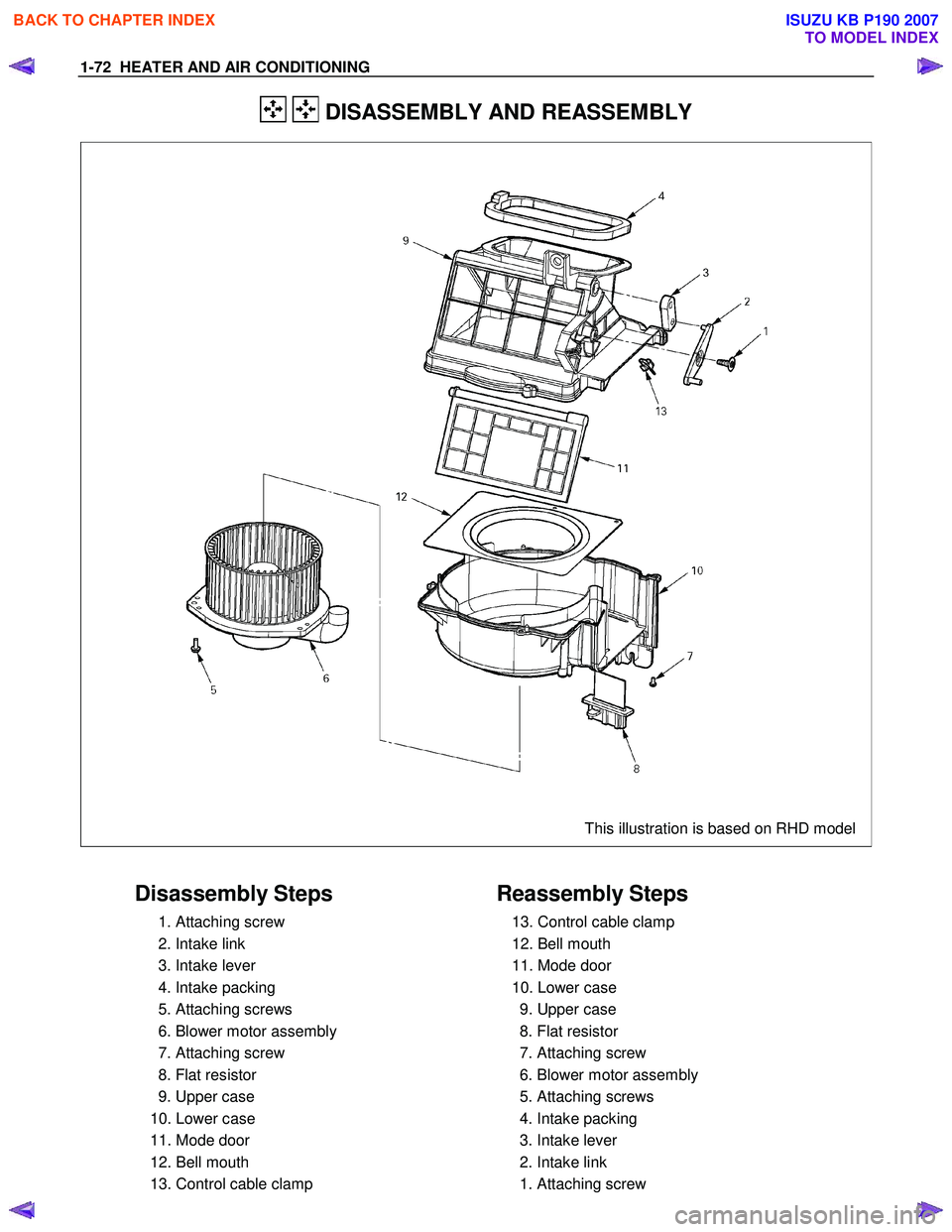
DISASSEMBLY AND REASSEMBLY
This illustration is based on RHD model
Disassembly Steps
1. Attaching screw
2. Intake link
3. Intake lever
4. Intake packing
5. Attaching screws
6. Blower motor assembly
7. Attaching screw
8. Flat resistor
9. Upper case
10. Lower case
11. Mode door
12. Bell mouth
13. Control cable clamp
Reassembly Steps
13. Control cable clamp
12. Bell mouth
11. Mode door
10. Lower case
9. Upper case
8. Flat resistor
7. Attaching screw
6. Blower motor assembly
5. Attaching screws
4. Intake packing
3. Intake lever
2. Intake link
1. Attaching screw
BACK TO CHAPTER INDEX
TO MODEL INDEX
ISUZU KB P190 2007
Page 115 of 6020
HEATER AND AIR CONDITIONING 1-81
INSPECTION AND REPAIR
840R300005-X
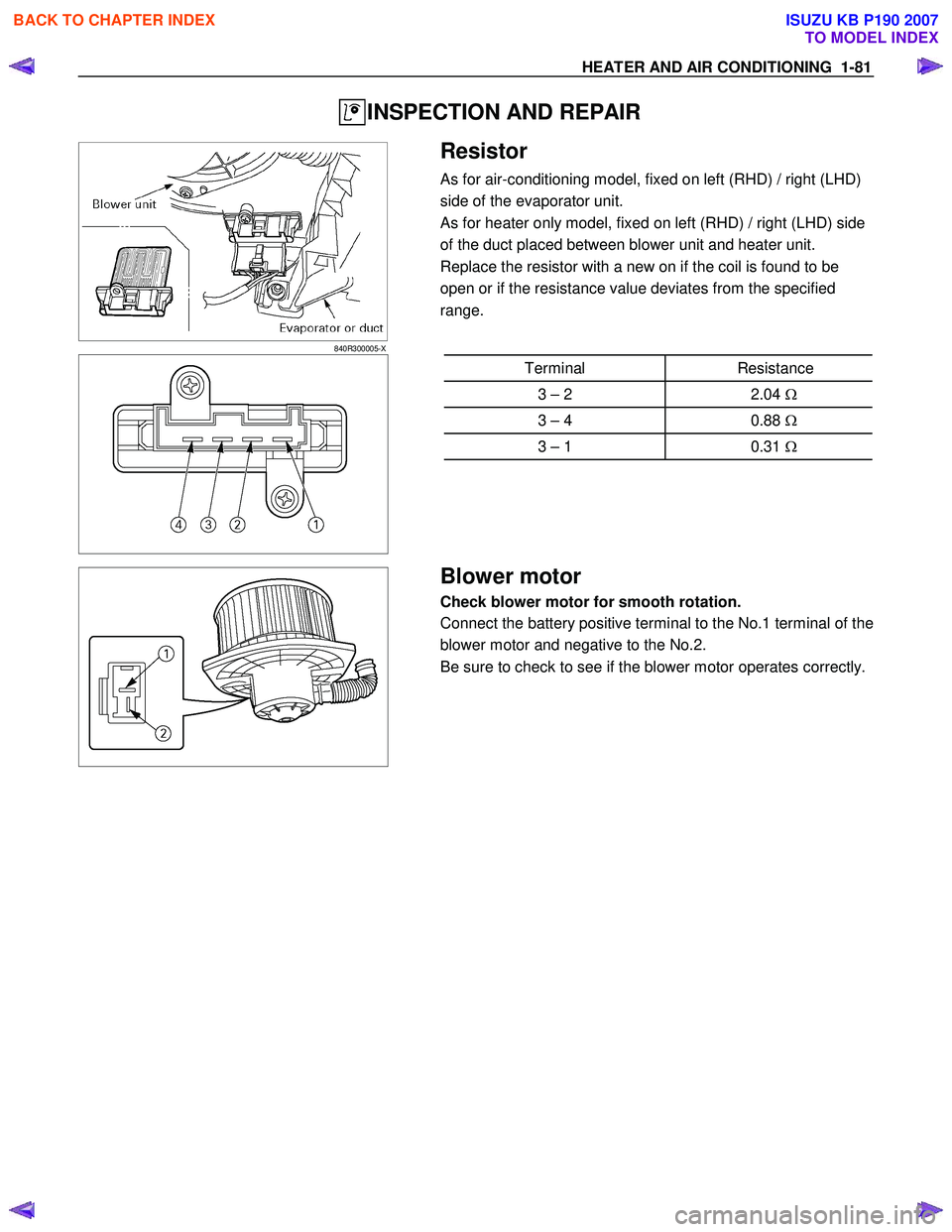
Resistor
As for air-conditioning model, fixed on left (RHD) / right (LHD)
side of the evaporator unit.
As for heater only model, fixed on left (RHD) / right (LHD) side
of the duct placed between blower unit and heater unit.
Replace the resistor with a new on if the coil is found to be
open or if the resistance value deviates from the specified
range.
Terminal Resistance
3 – 2 2.04 Ω
3 – 4 0.88 Ω
3 – 1 0.31 Ω
Blower motor
Check blower motor for smooth rotation.
Connect the battery positive terminal to the No.1 terminal of the
blower motor and negative to the No.2.
Be sure to check to see if the blower motor operates correctly.
BACK TO CHAPTER INDEX
TO MODEL INDEX
ISUZU KB P190 2007
Page 119 of 6020
HEATER AND AIR CONDITIONING 1-85
TROUBLESHOOTING
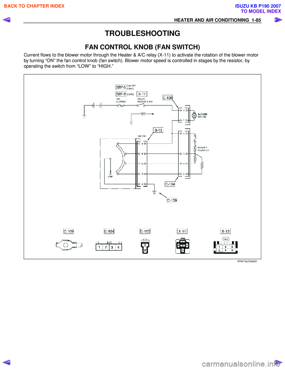
FAN CONTROL KNOB (FAN SWITCH)
Current flows to the blower motor through the Heater & A/C relay (X-11) to activate the rotation of the blower motor
by turning “ON” the fan control knob (fan switch). Blower motor speed is controlled in stages by the resistor, by
operating the switch from “LOW ” to “HIGH.”
RTW 710LF004201
BACK TO CHAPTER INDEX
TO MODEL INDEX
ISUZU KB P190 2007
Page 120 of 6020
1-86 HEATER AND AIR CONDITIONING
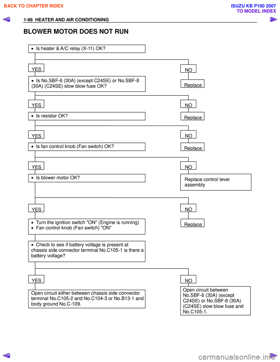
BLOWER MOTOR DOES NOT RUN
Replace
YES
• Is No.SBF-6 (30A) (except C24SE) or No.SBF-8
(30A) (C24SE) slow blow fuse OK?
• Is heater & A/C relay (X-11) OK?
YES
• Is resistor OK?
YES
• Is fan control knob (Fan switch) OK?
YES
YES
• Check to see if battery voltage is present at
chassis side connector terminal No.C105-1 is there a
battery voltage?
• Turn the ignition switch "ON" (Engine is running)
• Fan control knob (Fan switch) "ON"
• Is blower motor OK?
YES
Open circuit either between chassis side connector
terminal No.C105-2 and No.C104-3 or No.B13-1 and
body ground No.C-109.
NO
Replace
NO
Replace
NO
NO
Replace control lever
assembly
Replace
NO
NO
Open circuit between
No.SBF-6 (30A) (except
C24SE) or No.SBF-8 (30A)
(C24SE) slow blow fuse and
No.C105-1.
BACK TO CHAPTER INDEX
TO MODEL INDEX
ISUZU KB P190 2007
Page 121 of 6020

HEATER AND AIR CONDITIONING 1-87
BLOWER MOTOR DOES NOT RUN IN CERTAIN POSITION
A 1: (Low)
Blower motor does not
B 2: (Medium Low) Position
run at
C 3: (Medium Hi)
D 4: (High)
* Checkin
g is performed only when in the malfunction
mode.
•
Is resistor OK?
YES
•
Is fan control knob (Fan switch) OK?
YES
Condition:
•
O
pen circuit between chassis side connector
terminal No. C104-2 and No. B13-3
B Condition :
•
O
pen circuit between chassis side connector
terminal No. C104-4 and No. B13-6
C Condition:
•
O
pen circuit between chassis side connector
terminal No. C104-1 and No. B13-5
D Condition:
•
O
pen circuit between chassis side connector
terminal No. C105-2 and No. B13-4
Replace
NO
NO
Replace control leverassembly A
BACK TO CHAPTER INDEX
TO MODEL INDEX
ISUZU KB P190 2007