ignition ISUZU TF SERIES 2004 Repair Manual
[x] Cancel search | Manufacturer: ISUZU, Model Year: 2004, Model line: TF SERIES, Model: ISUZU TF SERIES 2004Pages: 4264, PDF Size: 72.63 MB
Page 127 of 4264

RESTRAINT CONTROL 9A1-57
DTC Will Clear When
The malfunction is no longer occurring and the ignition
is turned “OFF”.
DTC Chart Test Description
Number(s) below refer to step number(s) on the
diagnostic chart:
2.
This test determines whether the SRS control unit is
malfunctioning
3.
This test isolates the malfunction to one side of the
pretensioner assembly yellow connector at the base
of the driver seat.
4.
This test determines whether the malfunction is in
“Driver Pretensioner High” circuit.
5.
This test determines whether the malfunction is in
“Driver Pretensioner Low” circuit.
6.
This test determines whether the malfunction is in
“Driver Pretensioner High” circuit.
7.
This test determines whether the malfunction is in
“Driver Pretensioner Low” circuit.
8.
This test determines whether the malfunction is in
the driver pretensioner assembly.
Diagnostic Aids
An intermittent condition is likely to be caused by a short
to ground/+B in the driver pretensioner circuit. Inspect
circuits “Driver Pretensioner High” and “Driver
Pretensioner Low” carefully for cutting or chafing.
DTC B0066 (Flash Code 66) Driver Pretensioner Squib Circuit Voltage Range/Performance
Step Action Yes No
1 Was the “SRS Diagnostic System Check” performed? Go to Step 2 Go to the “SRS
Diagnostic System
Check”
2
1. When measurements are requested in this chart use 5-8840-
0285-0 DVM with correct terminal adapter from 5-8840-
0385-0.
2. Ignition switch “OFF.”
3. Ignition switch “ON.”
4. Check the driver pretensioner squib circuit for short to
voltage, short to ground and open.
Was a problem found? Verify repair Go to Step 3
3
1. Ignition switch “OFF.”
2. Disconnect pretensioner yellow connector located at base of
the driver seat. leave passenger pretensioner assembly
connected.
3. Connect SRS driver / passenger load tool 5-8840-2421-0 and
appropriate adapter to pretensioner harness connector.
4. ignition switch “ON.”
Is DTC B0066 current? Go to Step 4 Go to Step 8
4
1. Ignition switch “OFF.”
2. Disconnect SRS control unit.
3. Disconnect SRS driver / passenger load tool.
4. Measure resistance on SRS control unit harness connector
“42” to terminal “40” (ground).
Does 5-8840-0285-0 display “OL” (infinite)? Go to Step 5 Replace SRS
harness or repair
chassis harness.
Go to Step 9
Page 128 of 4264

9A1-58 RESTRAINT CONTROL SYSTEM
Step Action Yes No
5 Measure resistance on SRS control unit harness connector from
terminal “41” to terminal “40” (ground).
Does 5-8840-0285-0 display “OL” (infinite)? Go to Step 6
Replace SRS
harness.
Go to Step 9
6 Measure resistance on SRS control unit harness connector from
terminal “42” to terminal “35” (ignition).
Does 5-8840-0285-0 display “OL” (infinite)? Go to Step 7
Replace SRS
harness or repair
chassis harness.
Go to Step 9
7 Measure resistance on SRS control unit harness connector from
terminal “41” to terminal “35” (ignition).
Does 5-8840-0285-0 display “OL” (infinite)? Go to Chart A
Replace SRS
harness or repair
chassis harness.
Go to Step 9
8
1. Ignition switch “OFF.”
2. Disconnect SRS driver / passenger load tool 5-8840-2421-0
from pretensioner assembly harness connector.
3. Connect SRS driver / passenger load tool 5-8840-2421-0 and
appropriate adapter to driver pretensioner assembly harness
connector.
4. Reconnect pretensioner harness connector as the base of the
driver seat.
5. Ignition switch “ON.”
Is DTC B0066 current? Go to Step 9
Ignition switch
“OFF.”
Replace driver
pretensioner
assembly.
Go to Step 9
9
1. Reconnect all components ensure all component are properly
mounted.
2. Clear diagnostic trouble codes.
Was this step finished? Go to the “SRS
Diagnostic System
Check” Go to Step 9
Page 129 of 4264

RESTRAINT CONTROL 9A1-59
DTC B0670 (Flash Code 63) Airbag Telltale Circuit Malfunction
RTW49JLF000101
Circuit Description
When the ignition switch is turned “ON”, battery voltage
is applied to the “AIR BAG” warning lamp and to the
“Ignition 1” input terminal “35”. The SRS control unit
responds by flashing the “AIR BAG” warning lamp
seven times. The SRS control unit monitors the lamp
driver output by comparing the output state at “SRS
Warning Lamp” terminal “39” to the microprocesso
r
commanded state. When “Ignition 1” is in the specified
value, and the output state does not match the
commanded state of the lamp driver for 500
milliseconds, DTC B0670 is set.
DTC Will Set When
“Ignition 1” voltage is in the specified value and the
output state at the “SRS Warning Lamp” terminal does
not match the commanded state of the lamp driver for
500 milliseconds. This test is run every 100
milliseconds during “Continuous Monitoring” tests and
once per each ignition cycle at the beginning.
Action Taken
SRS control unit attempts to turn “ON” the “AIR BAG”
warning lamp and sets a diagnostic trouble code.
DTC Will Clear When
The ignition switch is turned “OFF.”
Page 130 of 4264

9A1-60 RESTRAINT CONTROL SYSTEM
DTC Chart Test Description
Refer to Charts B and C to diagnose warning lamp
circuit malfunctions.
DTC B0670 (Flash Code 63) Airbag Telltale Circuit Malfunction
Step Action Yes No
1 Was the “SRS Diagnostic System Check” performed? Go to Step 2 Go to the “SRS
Diagnostic System
Check”
2
1. Malfunctions within the “AIR BAG” warning lamp circuitry will
set this diagnostic trouble code.
2. These malfunctions are addressed in the “SRS Diagnostic
System Check” via Chart B and Chart C.
3. Failure to properly perform the “SRS Diagnostic System
Check” may result in misdiagnosis.
4. Ignition switch “ON.”
5. Clear SRS diagnostic trouble codes.
Is DTC B0670 set? Ignition switch
“OFF.”
Go to Chart A Repeat the “SRS
Diagnostic System
Check”
Page 131 of 4264

RESTRAINT CONTROL 9A1-61
DTC B1000 (Flash Code 72) SDM Internal Fault (SDM=SRS control unit)
RTW49JLF000101
Circuit Description
DTC B1000 is an indication of a potential internal SRS
control unit malfunction and will set if any of the
following conditions are detected:
1) Microprocessor energy reverse time failure.
2) EEPROM read / write failure.
3) ROM check sum.
4) Calibration check sum fault.
5) Inflators reserve voltage low.
6) Inflators electronic sensor active signal not detected
during commanded deployment.
7) QSDD (High-side/Low-side) FET failure.
8) Frontal accelerometer failure.
9) Phase lock loop lost lock.
10) QSDD communication fault.
DTC Will Set When
Any of the above indicated malfunctions are detected by
the SRS control unit. The malfunctions described
above are tested mainly during “Continuous Monitoring”
and some ones run each ignition cycle.
Action Taken
SRS control unit turns “ON” the “AIR BAG” warning
lamp and sets a diagnostic trouble code.
DTC Will Clear When
SRS control unit is replaced.
Page 132 of 4264

9A1-62 RESTRAINT CONTROL SYSTEM
DTC B1000 (Flash Code 72) SDM Internal Fault (SDM=SRS control unit)
WARNING: DURING SERVICE PROCEDURES. BE VERY CAREFUL WHEN HANDLING A SRS CONTROL
UNIT. NEVER STRIKE OR JAR THE SRS CONTROL UNIT. NEVER POWER UP THE SRS WHEN THE SRS
CONTROL UNIT IS NOT RIGIDLY ATTACHED TO THE VEHICLE. ALL SRS CONTROL UNIT AND MOUNTING
BRACKET FASTENERS MUST BE CAREFULLY TORQUED AND THE ARROW MUST BE POINTING TOWARD
THE FRONT OF THE VEHICLE TO ENSURE PROPER OPERATION OF THE SRS. THE SRS CONTROL UNIT
COULD BE ACTIVATED WHEN POWERED WHILE NOT RIGIDLY ATTACHED TO THE VEHICLE WHICH
COULD CAUSE DEPLOYMENT AND RESULT IN PERSONAL INJURY.
CAUTION: If DTC B1000 can not clear by Tech2, it is necessary to replace the SRS control unit.
Step Action Yes No
1 Was the “SRS Diagnostic System Check” performed? Ignition switch
“OFF.”
Replace SRS
control unit.
Repeat the “SRS
Diagnostic System
Check” Go to the “SRS
Diagnostic System
Check”
Page 329 of 4264

BRAKE CONTROL SYSTEM 5A-13
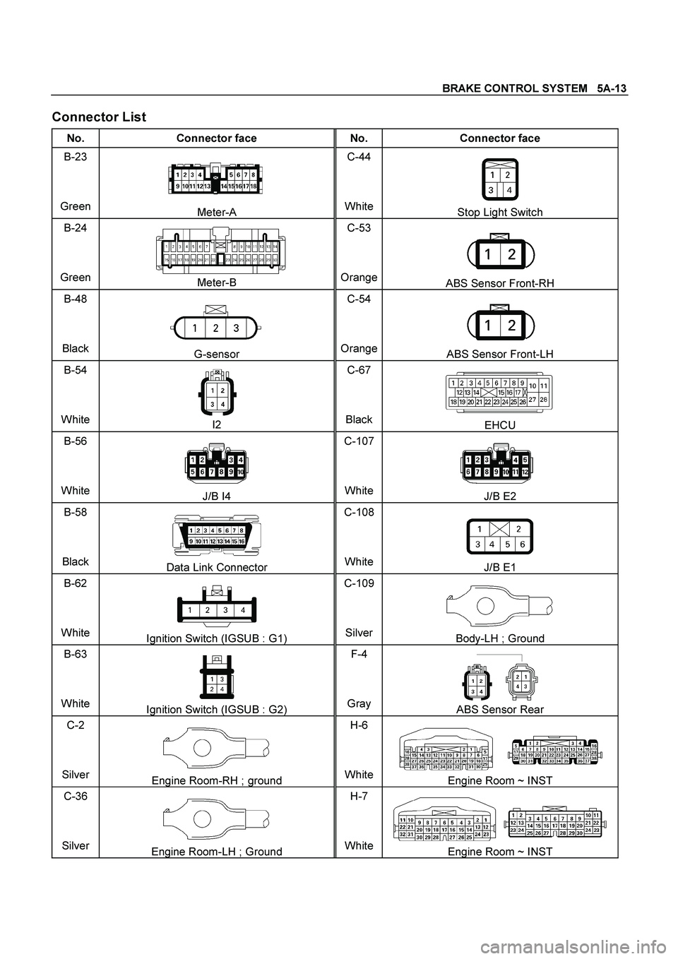
Connector List
No. Connector face No. Connector face
B-23
Green
Meter-A C-44
WhiteStop Light Switch
B-24
Green
Meter-B C-53
OrangeABS Sensor Front-RH
B-48
Black
G-sensor C-54
OrangeABS Sensor Front-LH
B-54
White
I2 C-67
BlackEHCU
B-56
White
J/B I4 C-107
WhiteJ/B E2
B-58
Black
Data Link Connector C-108
WhiteJ/B E1
B-62
White
Ignition Switch (IGSUB : G1) C-109
SilverBody-LH ; Ground
B-63
White
Ignition Switch (IGSUB : G2) F-4
Gray ABS Sensor Rear
C-2
Silver
Engine Room-RH ; ground H-6
WhiteEngine Room ~ INST
C-36
Silver
Engine Room-LH ; Ground H-7
WhiteEngine Room ~ INST
Page 335 of 4264

BRAKE CONTROL SYSTEM 5A-19
System Components
Electronic Hydraulic Control Unit (EHCU), four Wheel
Speed Sensors, two Warning Lamps, and G-sensor.
Electronic Hydraulic Control Unit (EHCU)
The EHCU consists of ABS control circuits, fault
detector, and a fail-safe. It drives the EHCU according
to the signal from each sensor, cancelling ABS to return
to normal braking when a malfunction has occurred in
the ABS.
The EHCU has a self-diagnosing function which can
indicate faulty circuits during diagnosis.
The EHCU is mounted on the engine compartment rear
left side. It consists of a motor, solenoid valves fail safe
relay.
Solenoid Valves: Reduces or holds the caliper fluid
pressure for each front brake or both rear brakes
according to the signal sent from the EHCU.
Buffer chamber: Temporarily holds the brake fluid that
returns from the front and rear brake so that pressure
of front brake can be reduced smoothly.
Motor: Drives the pump according to the signal from
EHCU.
Fail safe Relay: When failure occurs in ABS.
The power supply to solenoid Valve is cut.
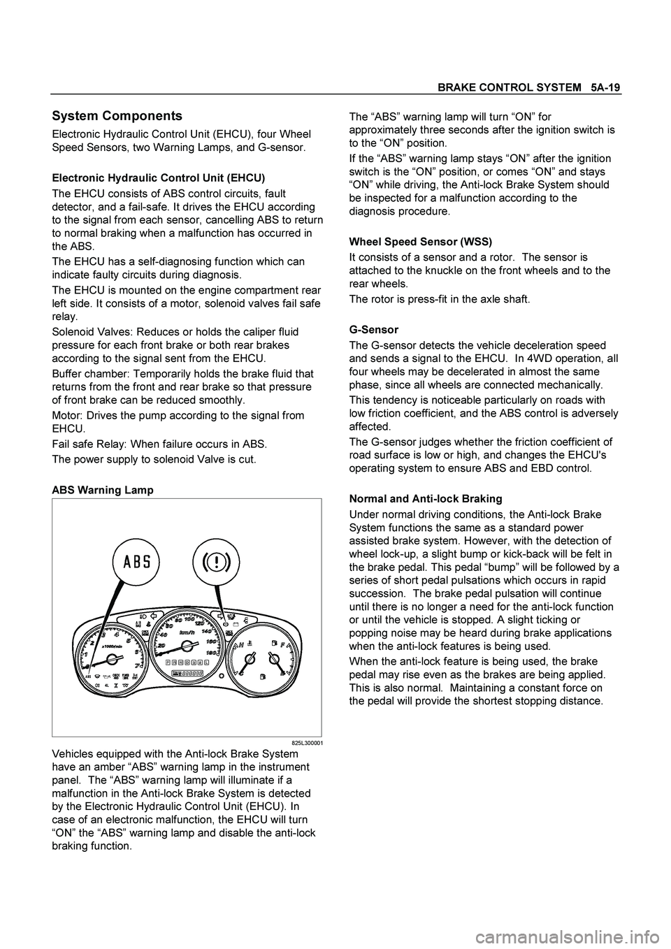
ABS Warning Lamp
825L300001
Vehicles equipped with the Anti-lock Brake System
have an amber “ABS” warning lamp in the instrument
panel. The “ABS” warning lamp will illuminate if a
malfunction in the Anti-lock Brake System is detected
by the Electronic Hydraulic Control Unit (EHCU). In
case of an electronic malfunction, the EHCU will turn
“ON” the “ABS” warning lamp and disable the anti-lock
braking function.
The “ABS” warning lamp will turn “ON” for
approximately three seconds after the ignition switch is
to the “ON” position.
If the “ABS” warning lamp stays “ON” after the ignition
switch is the “ON” position, or comes “ON” and stays
“ON” while driving, the Anti-lock Brake System should
be inspected for a malfunction according to the
diagnosis procedure.
Wheel Speed Sensor (WSS)
It consists of a sensor and a rotor. The sensor is
attached to the knuckle on the front wheels and to the
rear wheels.
The rotor is press-fit in the axle shaft.
G-Sensor
The G-sensor detects the vehicle deceleration speed
and sends a signal to the EHCU. In 4WD operation, all
four wheels may be decelerated in almost the same
phase, since all wheels are connected mechanically.
This tendency is noticeable particularly on roads with
low friction coefficient, and the ABS control is adversely
affected.
The G-sensor judges whether the friction coefficient of
road surface is low or high, and changes the EHCU's
operating system to ensure ABS and EBD control.
Normal and Anti-lock Braking
Under normal driving conditions, the Anti-lock Brake
System functions the same as a standard power
assisted brake system. However, with the detection of
wheel lock-up, a slight bump or kick-back will be felt in
the brake pedal. This pedal “bump” will be followed by a
series of short pedal pulsations which occurs in rapid
succession. The brake pedal pulsation will continue
until there is no longer a need for the anti-lock function
or until the vehicle is stopped. A slight ticking or
popping noise may be heard during brake applications
when the anti-lock features is being used.
When the anti-lock feature is being used, the brake
pedal may rise even as the brakes are being applied.
This is also normal. Maintaining a constant force on
the pedal will provide the shortest stopping distance.
Page 337 of 4264

BRAKE CONTROL SYSTEM 5A-21
Computer System Service Precautions
The Anti-lock Brake System and Electronic Brake-force
Distribution interfaces directly with the Electronic
Hydraulic Control Unit (EHCU) which is a control
computer that is similar in some regards to the Engine
Control Module. These modules are designed to
withstand normal current draws associated with vehicle
operation. However, care must be taken to avoid
overloading any of the EHCU circuits. In testing for
opens or shorts, do not ground or apply voltage to any
of the circuits unless instructed to do so by the
appropriate diagnostic procedure. These circuits should
only be tested with a high impedance multimeter
5-8840-0366-0 or special tools as described in this
section. Power should never be removed or applied to
any control module with the ignition in the “ON”
position.
Before removing or connecting battery cables, fuses or
connectors, always turn the ignition switch to the “OFF”
position.
General Service Precautions
The following are general precautions which should be
observed when servicing and diagnosing the Anti-lock
Brake System and/or other vehicle systems. Failure to
observe these precautions may result in Anti-lock Brake
System and Electronic Brake-force Distribution
damage.
If welding work is to be performed on the vehicle
using an electric arc welder, the EHCU and valve
block connectors should be disconnected before
the welding operation begins.
The EHCU and valve block connectors should
never be connected or disconnected with the
ignition “ON”.
Note:
If only rear wheels are rotated using jacks or drum
tester, the system will diagnose a speed sensor
malfunction and the “ABS and Brake” warning lamp
will illuminate. But actually no trouble exists. When
the DTC is not detected and the ABS and BRAKE
warning lamp is on, “How to erase code” is
performed and a ABS and BRAKE warning lamp
are off.
If the battery has been discharged
The engine may stall if the battery has been completely
discharged and the engine is started via jumper cables.
This is because the Anti-lock Brake System (ABS) and
Electronic Brake-force Distribution (EBD) System
requires a large quantity of electricity. In this case, wait
until the battery is recharged, or set the ABS and EBD
to a non-operative state by removing the fuse for the
ABS. After the battery has been recharged, stop the
engine and install the ABS fuse. Start the engine again,
and confirm that the ABS warning Lamp does not light.
Note on Intermittents
As with virtually any electronic system, it is difficult to
identify an intermittent failure. In such a case
duplicating the system malfunction during a test drive or
a good description of vehicle behavior from the
customer may be helpful in locating a “most likely”
failed component or circuit. The symptom diagnosis
chart may also be useful in isolating the failure. Most
intermittent problems are caused by faulty electrical
connections or wiring. When an intermittent failure is
encountered, check suspect circuits for:
Suspected harness damage.
Poor mating of connector halves or terminals not
fully seated in the connector body (backed out).
Improperly formed or damaged terminals.
Test Driving ABS Complaint Vehicles
In case that there has been an abnormality in the
lighting pattern of “ABS” warning lamp, the fault can be
located in accordance with the “DIAGNOSIS BY “ABS”
WARNING LAMP ILLUMINATION PATTERN”. In case
of such trouble as can be detected by the driver as a
vehicle symptom, however, it is necessary to give a test
drive following the test procedure mentioned below,
thereby reproducing the symptom for trouble diagnosis
on a symptom basis:
1.
Start the engine and make sure that the “ABS” W/L
goes OFF. If the W/L remains ON, it means that
the Diagnostic Trouble Code (DTC) is stored.
Therefore, read the code and locate the fault.
Note: The DTC cannot be cleared if the vehicle speed
does not exceed about 6km/h (4mph) at DTC, even
though the repair operation is completed.
2. Start the vehicle and accelerate to about 30 km/h
(19 mph) or more.
3. Slowly brake and stop the vehicle completely.
4. Then restart the vehicle and accelerate to about 40
km/h (25 mph) or more.
5. Brake at a time so as to actuate the ABS and stop
the vehicle.
6. Be cautious of abnormality during the test. If the
W/L is actuated while driving, read the DTC and
locate the fault.
7. If the abnormality is not reproduced by the test,
make best efforts to reproduce the situation
reported by the customer.
8. If the abnormality has been detected, repair in
accordance with the “SYMPTOM DIAGNOSIS” .
Note:
Be sure to give a test drive on a wide, even road
with a small traffic.
If an abnormality is detected, be sure to suspend
the test and start trouble diagnosis at once.
Page 338 of 4264

5A-22 BRAKE CONTROL SYSTEM
“ABS” Warning Lamp
When ABS and trouble occurs to actuate “ABS”
warning lamp, the trouble code corresponding to the
trouble is stored in the EHCU. Only ordinary brake is
available with ABS being unactuated. Even when
“ABS” warning lamp is actuated, if the starter switch is
set ON after setting it OFF once, the EHCU checks up
on the entire system and, if there is no abnormality,
judges ABS to work currently and the warning lamp is lit
normally even though the trouble code is stored.
NOTE: Illumination of the “ABS” warning lamp indicates
that anti-lock braking is no longer available. Power
assisted braking without anti-lock control is still
available.
Normal Operation
“ABS ” Warning Lamp
When the ignition is first moved from “OFF” to “RUN”,
the amber “ABS” warning lamp will turn “ON”. The
“ABS” warning lamp will turn “ON” during engine
starting and will usually stay “ON” for approximately
three seconds after the ignition switch is returned to the
“ON” position. The warning lamp should remain “OFF”
at all other times.
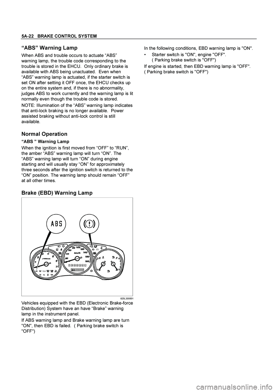
Brake (EBD) Warning Lamp
825L300001
Vehicles equipped with the EBD (Electronic Brake-force
Distribution) System have an have “Brake” warning
lamp in the instrument panel.
If ABS warning lamp and Brake warning lamp are turn
"ON", then EBD is failed. ( Parking brake switch is
"OFF")
In the following conditions, EBD warning lamp is "ON".
Starter switch is "ON", engine "OFF".
( Parking brake switch is "OFF")
If engine is started, then EBD warning lamp is "OFF".
( Parking brake switch is "OFF")