key ISUZU TROOPER 1995 Workshop Manual
[x] Cancel search | Manufacturer: ISUZU, Model Year: 1995, Model line: TROOPER, Model: ISUZU TROOPER 1995Pages: 1928
Page 22 of 1928
OB-6 MAINTENANCE AND LUBRICATION
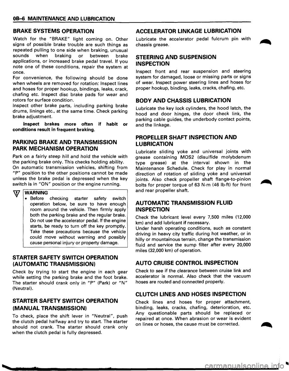
BRAKE SYSTEMS OPERATION
Watch for the "BRAKE" light coming on. Other
signs of possible brake trouble are such things as
repeated pulling to one side when braking, unusual
sounds
when braking or between brake
applications,
or increased brake pedal travel. If you
note one of these conditions, repair the system at
once.
For convenience, the
following should be done
when wheels are removed for rotation: Inspect lines
and hoses
for proper hookup, bindings, leaks, crack,
chafing etc.
Inspect disc brake pads for wear and
rotors
for surface condition.
Inspect other brake parts, including parking brake
drums, linings etc., at the same time. Check parking
brake adjustment.
Inspect brakes more often if habit or
conditions
result in frequent braking.
PARKING BRAKE AND TRANSMISSION
PARK MECHANISM OPERATION
Park on a fairly steep hill and hold the vehicle with
the parking brake only. This checks holding ability.
On
automatic transmission vehicles, shifting from
"P" position to the other positions cannot be made
unless
the brake pedal is depressed when the key
switch is in
"ON" position or the engine running.
WARNING
•
Before checking starter safety switch
operation below,
be sure to have enough
room around the
vehicle. Then firmly apply
both the parking brake and the regular brake.
Do not
use the accelerator pedal. If the engine
starts, be ready
to turn off the key promptly.
Take these precautions because the vehicle
could move
without warning and possibly
cause personal injury
or property damage.
STARTER SAFETY SWITCH OPERATION
(AUTOMATIC TRANSMISSION)
Check by trying to start the engine in each gear
while setting the parking brake and the foot brake.
The starter
should crank only in "P" (Park) or "N"
(Neutral).
STARTER SAFETY SWITCH OPERATION
(MANUAL TRANSMISSION)
To check, place the shift lever in "Neutral", push
the clutch pedal halfway and try to start. The starter
should not crank. The starter should crank only
when the clutch pedal is fully depressed.
ACCELERATOR LINKAGE LUBRICATION
Lubricate the accelerator pedal fulcrum pin with
chassis grease.
STEERING AND SUSPENSION
INSPECTION
Inspect front and rear suspension and steering
system
for damaged, loose or missing parts or signs
of wear. Inspect power steering lines and hoses for
proper hookup, binding, leaks, cracks, chafing, etc.
BODY AND CHASSIS LUBRICATION
Lubricate the key lock cylinders, the hood latch, the
hood and door hinges, the door check link, the
parking cable guides,
the underbody contact points,
and the linkage.
PROPELLER SHAFT INSPECTION AND
LUBRICATION
Lubricate sliding yoke and universal joints with
grease containing MOS2 (disulfide molybdenum
type grease) at the interval shown in the
Maintenance Schedule. Check for play in normal
direction of rotation of sliding yoke and universal
joints. Also check
propeller shaft flange-to-pinion
bolts for proper torque of 63 N·m (46 lb·ft) for front
and rear propeller shaft.
AUTOMATIC TRANSMISSION FLUID
INSPECTION
Check the lubricant level every 7,500 miles (12,000
km) and add lubricant
if necessary.
Under harsh operating conditions, such as constant
driving in heavy city traffic during
hot weather, or in
hilly or mountainous terrain, change the transmission
fluid and service the
sump filter after every 20,000
miles (32,000 km) of operation.
AUTO CRUISE CONTROL INSPECTION
Check to see if the clearance between cruise link and
accelerator is normal. Also check that the vacuum
hoses are routed and connected properly.
CLUTCH LINES AND HOSES INSPECTION
Check lines and hoses for proper attachment,
binding, leaks, cracks, chafing, deterioration, etc.
Any questionable parts should be replaced or
repaired at once. When abrasion or wear is evident
on lines or hoses, the cause must be corrected.
..
Page 24 of 1928
OB-8 MAINTENANCE AND LUBRICATION
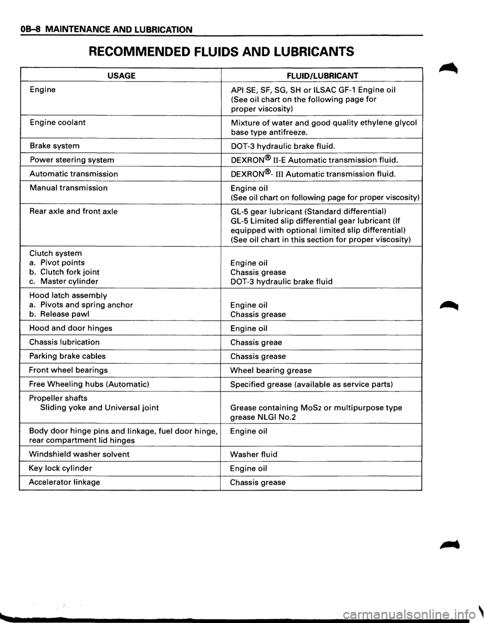
RECOMMENDED FLUIDS AND LUBRICANTS
USAGE FLUID/LUBRICANT
Engine API SE, SF, SG, SH or ILSAC GF-1 Engine oil
(See oil
chart on the following page for
proper viscosity)
Engine
coolant Mixture of water and good quality ethylene glycol
base type antifreeze.
Brake system
DOT-3 hydraulic brake fluid.
Power steering system
DEXRON® 11-E Automatic transmission fluid.
Automatic transmission DEXRON®-III Automatic transmission fluid.
Manual transmission
Engine oil
(See oil
chart on following page for proper viscosity)
Rear
axle and front axle GL-5 gear lubricant (Standard differential)
GL-5 Limited slip differential gear lubricant (If
equipped with optional limited slip differential)
(See oil
chart in this section for proper viscosity)
Clutch system
a. Pivot points Engine oil
b. Clutch fork joint Chassis grease
c. Master cylinder DOT-3 hydraulic brake fluid
Hood latch assembly
a. Pivots and spring anchor
Engine oil
b. Release pawl Chassis grease
Hood and
door hinges
Engine oil
Chassis lubrication Chassis greae
Parking brake
cables Chassis grease
Front wheel bearings Wheel bearing grease
Free
Wheeling hubs (Automatic) Specified grease (available as service parts)
Propeller shafts
Sliding yoke and Universal joint Grease containing MoS2 or multipurpose type
grease NLGI No.2
Body
door hinge pins and linkage, fuel door hinge,
Engine oil
rear compartment lid hinges
Windshield washer solvent Washer fluid
Key lock cylinder Engine oil
Accelerator linkage
Chassis grease
Page 127 of 1928
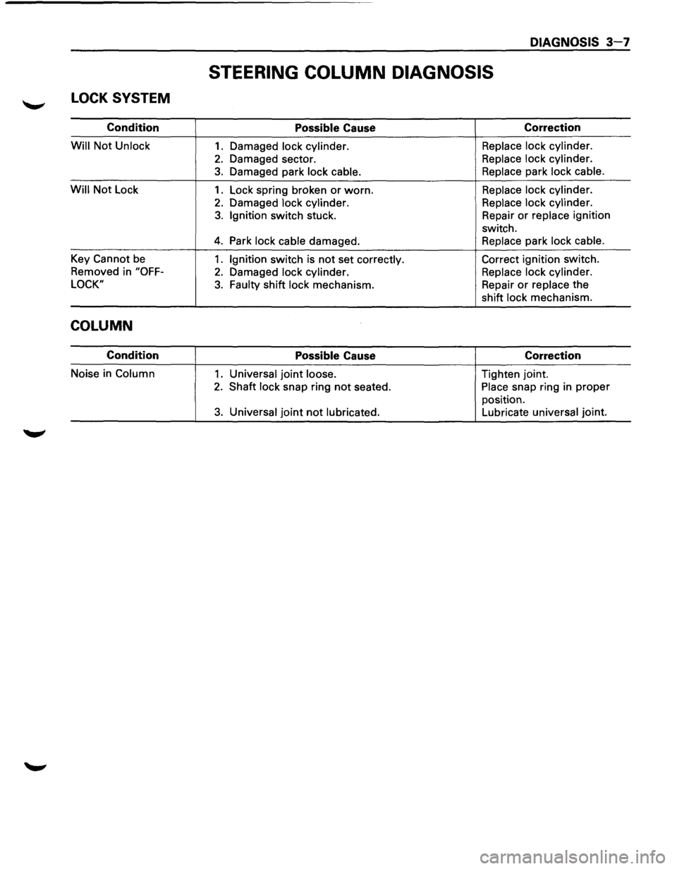
LOCK SYSTEM
Condition
Will Not Unlock
Will Not Lock
Key
Cannot be
Removed in "OFF-
LOCK"
COLUMN
Condition
Noise in Column
DIAGNOSIS 3-7
STEERING COLUMN DIAGNOSIS
Possible Cause
1. Damaged lock cylinder.
2. Damaged sector.
3. Damaged park lock cable.
1. Lock spring broken or worn.
2. Damaged lock cylinder.
3. Ignition switch stuck.
4. Park lock cable damaged.
1. Ignition switch is not set correctly.
2. Damaged lock cylinder.
3. Faulty shift lock mechanism.
Possible Cause
1. Universal joint loose.
2. Shaft lock snap ring not seated.
3. Universal joint not lubricated.
Correction
Replace lock cylinder.
Replace lock cylinder.
Replace park lock cable.
Replace lock cylinder.
Replace lock cylinder.
Repair
or replace ignition
switch.
Replace park lock cable.
Correct ignition switch.
Replace lock cylinder.
Repair
or replace the
shift lock mechanism.
Correction
Tighten joint.
Place snap ring in proper
position.
Lubricate universal joint.
Page 311 of 1928
7.
Fig. 4C-90
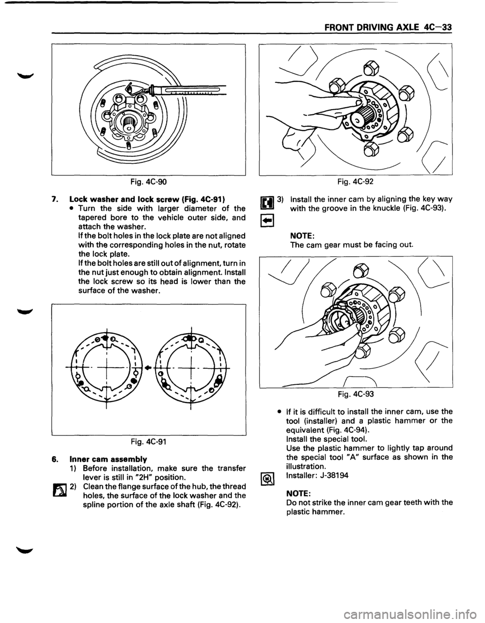
Lock washer and lock screw (Fig. 4C-91}
• Turn the side with larger diameter of the
tapered bore
to the vehicle outer side, and
attach the washer.
If the bolt holes in the lock plate are not aligned
with the corresponding holes in the nut, rotate
the
lock plate.
If
the bolt holes are still out of alignment, turn in
the
nut just enough to obtain alignment. Install
the lock screw so its head is lower than the
surface
of the washer .
•
Fig. 4C-91
6. Inner cam assembly
1) Before installation, make sure the transfer
lever is still in "2H" position.
1!1::1 2) Clean the flange surface of the hub, the thread
Lil holes, the surface of the lock washer and the
spline portion of the axle shaft (Fig. 4C-92).
FRONT DRIVING AXLE 4C-33
Fig. 4C-92
Install the inner cam by aligning the key way
with the groove in the knuckle (Fig. 4C-93).
NOTE:
The cam gear must be facing out.
Fig. 4C-93
• If it is difficult to install the inner cam, use the
tool (installer) and a plastic hammer or the
equivalent (Fig. 4C-94).
Install the special tool.
Use the plastic hammer to lightly tap around
the
special tool "A" surface as shown in the
illustration.
Installer:
J-38194
NOTE:
Do not strike the inner cam gear teeth with the
plastic hammer.
Page 329 of 1928
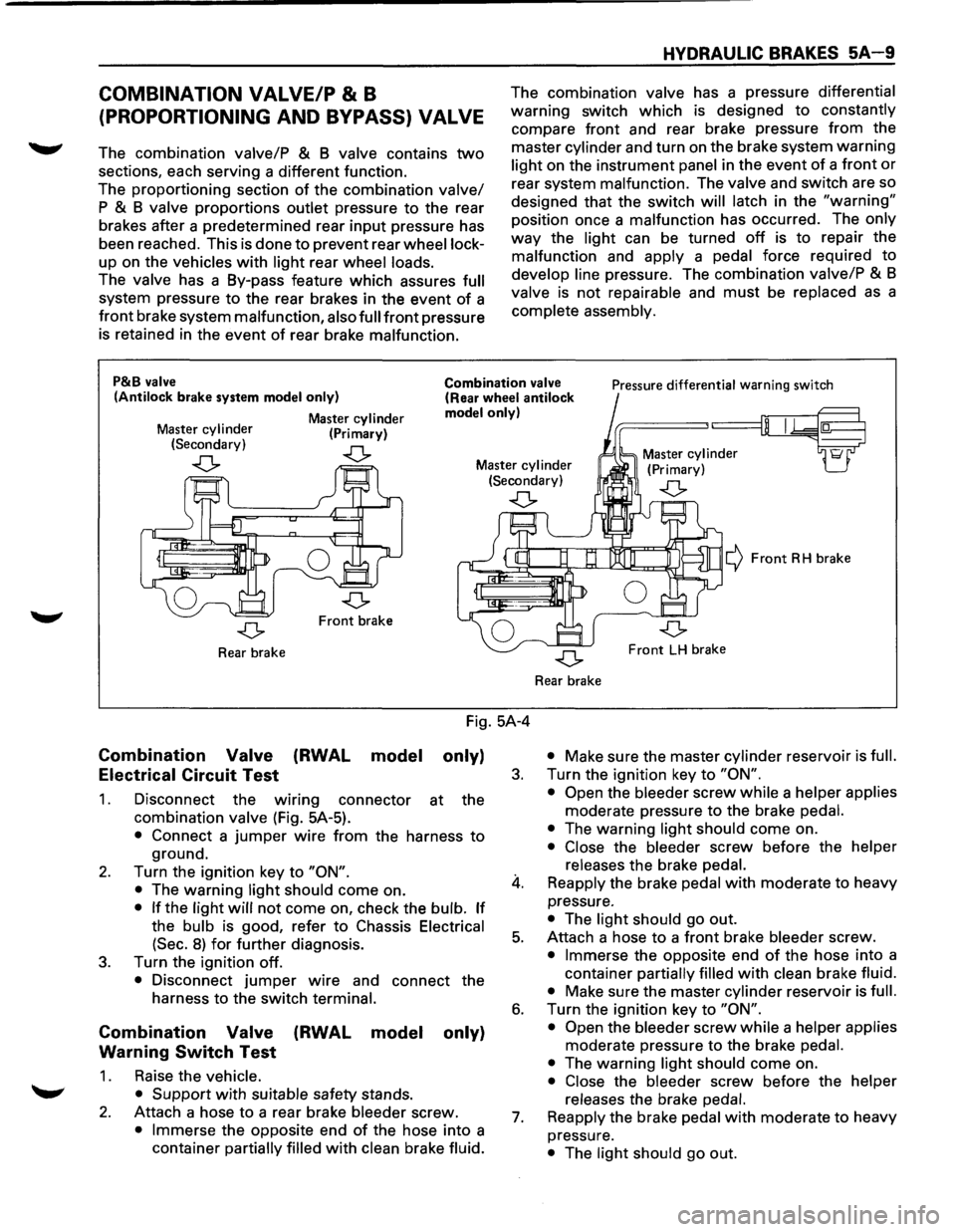
COMBINATION VALVE/P & B
(PROPORTIONING AND BYPASS) VALVE
The combination valve/P & B valve contains two
sections, each serving a different function.
The proportioning section
of the combination valve/
P & B valve proportions outlet pressure to the rear
brakes after a predetermined rear
input pressure has
been reached. This is done to prevent rear
wheel lock
up on the vehicles with light rear wheel loads.
The valve has a By-pass feature which assures full
system pressure to the rear brakes in the event of a
front brake system malfunction, also full front pressure
is retained in the event
of rear brake malfunction.
HYDRAULIC BRAKES 5A 9
The combination valve has a pressure differential
warning switch which is designed to constantly
compare front and rear brake pressure
from the
master
cylinder and turn on the brake system warning
light on the instrument panel in the event of a front or
rear system malfunction. The valve and switch are so
designed that the switch
will latch in the "warning"
position once a malfunction has occurred. The only
way the light can be turned off is to repair the
malfunction and
apply a pedal force required to
develop line pressure. The combination valve/P & B
valve is not repairable and must be replaced as a
complete assembly.
P&B valve
(Antilock brake system model only)
Master cylinder (Primary)
Combination valve (Rear wheel antilock model only)
Pressure differential warning switch
Master
cylinder (Secondary)
..(> ..(> Master cylinder (Secondary) Master
cylinder
(Primary)
..(> ..(>
Front brake
Rear brake
Combination Valve
Electrical Circuit Test (RWAL
model
Fig. 5A-4
only)
1.
2.
3.
Disconnect the wmng connector at the
combination
valve (Fig. 5A-5).
• Connect a jumper wire from the harness to
ground.
Turn the ignition key to
"ON".
•
The warning light should come on.
• If the light will not come on, check the bulb. If
the bulb is good, refer to Chassis Electrical
(Sec.
8) for further diagnosis.
Turn the ignition off.
• Disconnect jumper wire and connect the
harness to the switch
terminal.
Combination Valve (RWAL model only)
Warning
Switch Test
1. Raise the vehicle.
• Support
with suitable safety stands.
2. Attach a hose to a rear brake bleeder screw.
• Immerse the opposite end of the hose into a
container
partially filled with clean brake fluid.
3.
4.
5.
6.
7.
¢ Front RH brake
Front LH brake
Rear brake
• Make sure the master cylinder reservoir is full.
Turn the ignition key to "ON".
• Open
the bleeder screw while a helper applies
moderate pressure to the brake pedal.
•
The warning light should come on.
• Close the bleeder screw before the helper
releases
the brake pedal.
Reapply the brake pedal with moderate to heavy
pressure.
• The light should go out.
Attach a hose
to a front brake bleeder screw.
• Immerse the opposite end of the hose into a
container
partially filled with clean brake fluid.
• Make sure the master cylinder reservoir is full.
Turn the ignition key to "ON".
• Open
the bleeder screw while a helper applies
moderate pressure to the brake pedal.
•
The warning light should come on.
• Close the bleeder screw before the helper
releases
the brake pedal.
Reapply
the brake pedal with moderate to heavy
pressure.
• The light should go out.
Page 330 of 1928
5A-1 0 HYDRAULIC BRAKES
8. Turn the ignition key off.
• If the warning light does not come on during
steps 3 and
6, but does light when a jumper is
connected to ground, the warning switch
portion
of the valve is faulty. Do not
disassemble any portion of the valve. It must
be replaced.
9. Remove the safety stands.
• Lower the vehicle.
• Check and fill the master cylinder to the proper
level.
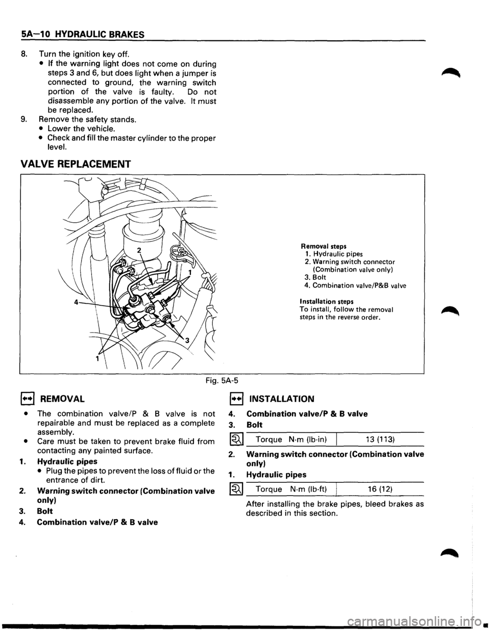
VALVE REPLACEMENT
Removal steps 1. Hydraulic pipes
2. Warning switch
connector (Combination valve only)
3. Bolt
4. Combination valve/P&B valve
Installation
steps
To install, follow the removal steps in the reverse order.
Fig. 5A-5
1••1 REMOVAL
• The combination valve/P & 8 valve is not
repairable and must be replaced as a complete
assembly.
• Care must be taken to prevent brake fluid from
contacting any painted surface.
1. Hydraulic pipes
• Plug the pipes to prevent the loss of fluid or the
entrance
of dirt.
2. Warning switch connector (Combination valve
only)
3. Bolt
4. Combination valve/P & B valve
1••1 INSTALLATION
4.
3. Combination valve/P & B valve
Bolt
I~I_T_o_r_qu_e_N_·_m_(lb_·_in_) ___,_ ___ 1_3_(_1_13_) __ _
2. Warning switch connector (Combination valve
only)
1. Hydraulic pipes
~~~ Torque N·m (lb·ft) 16 (12)
After installing the brake pipes, bleed brakes as
described in this section.
•
Page 375 of 1928
REAR WHEEL ANTILOCK BRAKE SYSTEM 5A3-7
REAR WHEEL ANTILOCK (RWAL) SYSTEM DIAGNOSTICS
DIAGNOSIS PROCEDURE
The RWAL system contains 13 diagnostic trouble
codes
for system troubleshooting. With the ignition
key turned
ON, momentarily grounding the RWAL
diagnostic lead
with the "Rr ABS" light on will cause the
light
to flash out a diagnostic trouble code if a failure
has been detected and is in memory.
Some RWAL
diagnostic trouble codes require a road test in order
to
be set into the EBCM memory.
RWAL diagnostic trouble codes are cleared from
the
EBCM memory every time the ignition key is
turned off. If a diagnostic trouble code is not present, a
test drive
must be performed to reproduce the failure
and reset the code into
memory:
TEST DRIVING
1. Conduct a visual check of the following items to
see if any abnormalities exist:
(a) Service brake mechanism/hydraulic system
(See BRAKE SERVICING SECTION).
(b) Fuses #2, #7, #14 and main fuse
(c) RWAL-related connector (check for loose pins
and rust)
(d) EBCM and valve ground (check for looseness
and rust)
NOTE:
Check
(c) and (d) should be done with ignition key
turned
OFF.
If any abnormality is found, perform repairs as
required.
2. Turn the ignition switch ON. As a self-check, the
"Rr ABS" light should come on for approximately
2 seconds, then go
off and remain off.
If the "Rr ABS" light remains on or comes back
on, check
for diagnostic trouble codes by
momentarily grounding the RWAL diagnostic
lead
with the "Rr ABS" light on. -
If the "Rr
ABS" light self-check operates
properly, continue
with the test drive below.
3. Test driving vehicle:
(a) Start the engine and begin driving the vehicle.
(b) Accelerate to 40 mph.
(c) At least once, brake to a full stop using enough
brake pedal force
to activate the RWAL
system.
(d) Accelerate to 60 mph and continue to run at
this speed
for 5 minutes.
4. If a diagnostic trouble code is obtained.
inspect in accordance
with the appropriate
"FLASHOUT DIAGNOSTIC TROUBLE CODES
CHART".
If
no diagnostic trouble code is found, and the
"Rr ABS" and "BRAKE" light comes on, or if
any abnormal operation occurs during the
test drive, inspect in accordance
with CHART
C, "Rr ABS AND BRAKE LIGHTS ON".
5. If the "Rr ABS" or "BRAKE" light does not come
during the test drive, ask the customer under
what conditions the light came on. Then try to
duplicate the complaint condition
as closely as
possible.
If no problem is found, check all underhood
connections that supply power
to the RWAL and
ignition fuses, inspect
all RWAL harness
connectors, and inspect the
EBCM and anti-lock
valve ground connections.
Do not assume that the
EBCM is bad because the
"Rr ABS" or "BRAKE" lights are on. In most cases,
it is telling you it has found a problem elsewhere.
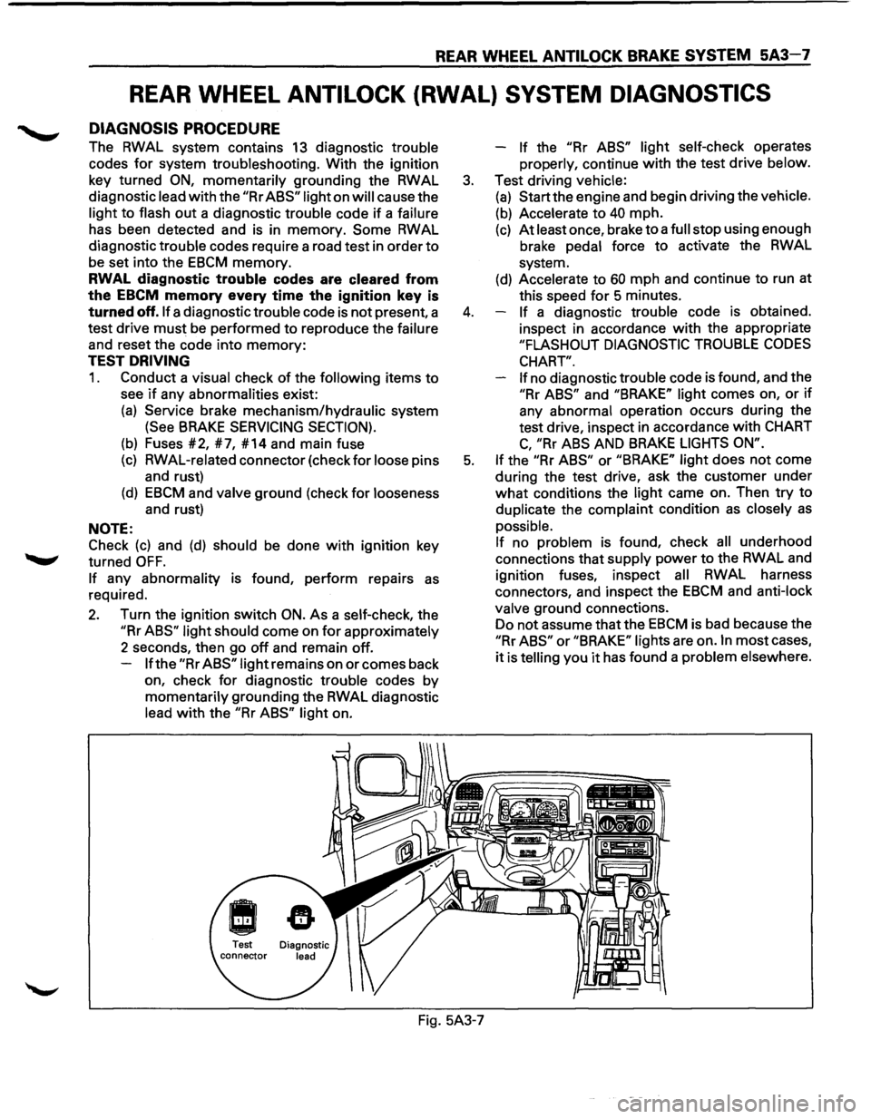
Fig. 5A3-7
Page 380 of 1928
5A3~12 REAR WHEEL ANTILOCK BRAKE SYSTEM
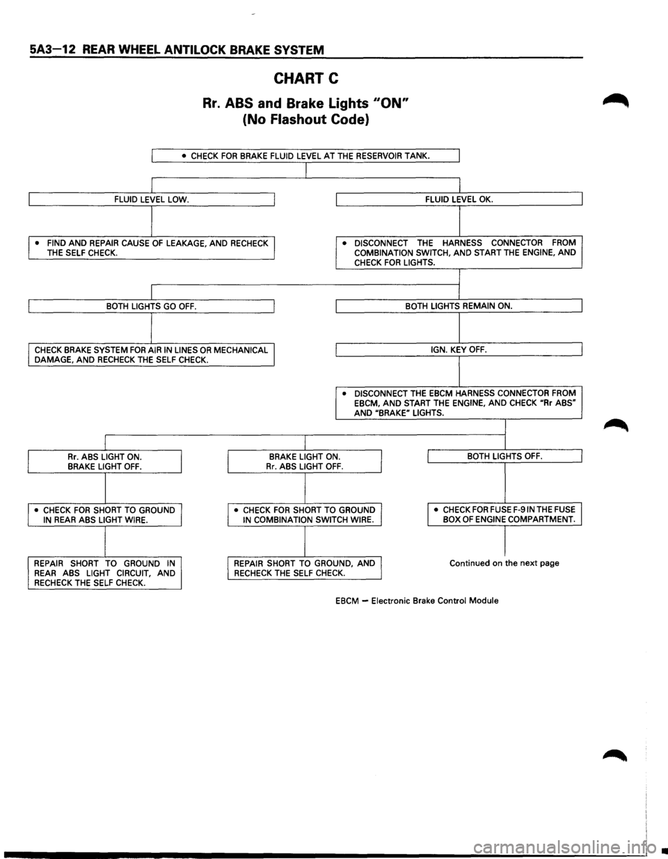
CHART C
Rr. ABS and Brake Lights 110N"
(No Flashout Code}
I • CHECK FOR BRAKE FLUID LEVEL AT THE RESERVOIR TANK.
I
I FLUID LEVEL LOW. I FLUID LEVEL OK.
I
• FIND AND REPAIR CAUSE OF LEAKAGE, AND RECHECK I • DISCONNECT THE HARNESS CONNECTOR FROM THE
SELF CHECK. COMBINATION SWITCH, AND START THE ENGINE, AND CHECK FOR LIGHTS.
I BOTH LIGHTS GO OFF. I BOTH LIGHTS REMAIN ON.
I
CHECK BRAKE SYSTEM FOR AIR IN LINES OR MECHANICAL I IGN. KEY OFF. DAMAGE, AND RECHECK THE SELF CHECK.
• DISCONNECT THE EBCM HARNESS CONNECTOR FROM EBCM, AND START THE ENGINE, AND CHECK uRr ABS" AND UBRAKE" LIGHTS.
I Rr. ABS LIGHT ON.
I
BRAKE LIGHT ON.
I I BOTH LIGHTS OFF. BRAKE LIGHT OFF. Rr. ABS LIGHT OFF.
I • CHECK FOR SHORT TO GROUND I • CHECK FOR SHORT TO GROUND I I
• CHECK FOR FUSE F-91N THE FUSE IN REAR ABS LIGHT WIRE. IN COMBINATION SWITCH WIRE. BOX OF ENGINE COMPARTMENT.
I I REPAIR
SHORT TO GROUND IN I REPAIR SHORT TO GROUND, AND J Continued on the next page REAR ABS LIGHT CIRCUIT, AND RECHECK THE SELF
CHECK.
RECHECK THE SELF CHECK.
EBCM -
Electronic Brake Control Module
•
Page 381 of 1928
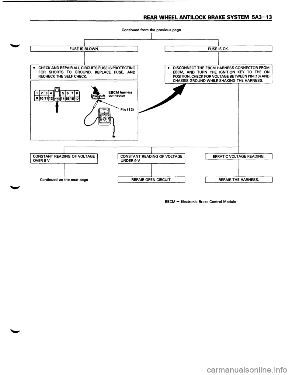
REAR WHEEL ANTILOCK BRAKE SYSTEM 5A3-13
Continued from the previous page
• CHECK AND REPAIR ALL CIRCUITS FUSE IS PROTECTING FOR SHORTS TO GROUND. REPLACE FUSE, AND RECHECK THE SELF CHECK. •
DISCONNECT
THE EBCM HARNESS CONNECTOR FROM
EBCM, AND TURN THE IGNITION KEY TO THE ON POSITION, CHECK FOR VOLTAGE BETWEEN PIN (13) AND CHASSIS GROUND WHILE SHAKING THE HARNESS.
CONSTANT READING OF VOLTAGE OVER 9V CONSTANT READING OF VOLTAGE UNDER9V
Continued on the next page
EBCM -
Electronic Brake Control Module
Page 383 of 1928
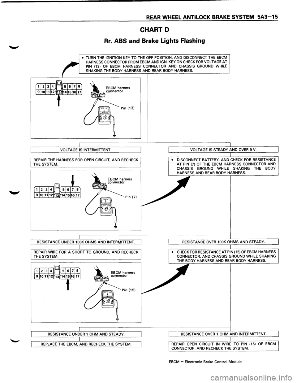
REAR WHEEL ANTILOCK BRAKE SYSTEM 5A3-15
CHART D
Rr. ABS and Brake Lights Flashing
• TURN THE IGNITION KEY TO THE OFF POSITION, AND DISCONNECT THE EBCM HARNESS CONNECTOR FROM EBCM AND IGN. KEY ON CHECK FOR VOLTAGE AT PIN {13) OF EBCM HARNESS CONNECTOR AND CHASSIS GROUND WHILE
SHAKING THE BODY HARNESS AND REAR BODY HARNESS.
REPAIR THE HARNESS FOR OPEN CIRCUIT, AND RECHECK • DISCONNECT BATTERY, AND CHECK FOR RESISTANCE AT PIN {7) OF THE EBCM HARNESS CONNECTOR AND CHASSIS GROUND WHILE SHAKING THE BODY
HARNESS AND REAR BODY HARNESS.
THE SYSTEM.
•
CHECK FOR RESISTANCE AT PIN {15) OF EBCM HARNESS
CONNECTOR, AND CHASSIS GROUND WHILE SHAKING THE BODY HARNESS AND REAR BODY HARNESS.
REPAIR OPEN CIRCUIT
IN WIRE TO PIN {15) CONNECTOR, AND RECHECK THE SYSTEM.
EBCM = Electronic Brake Control Module