key ISUZU TROOPER 1995 Workshop Manual
[x] Cancel search | Manufacturer: ISUZU, Model Year: 1995, Model line: TROOPER, Model: ISUZU TROOPER 1995Pages: 1928
Page 1760 of 1928
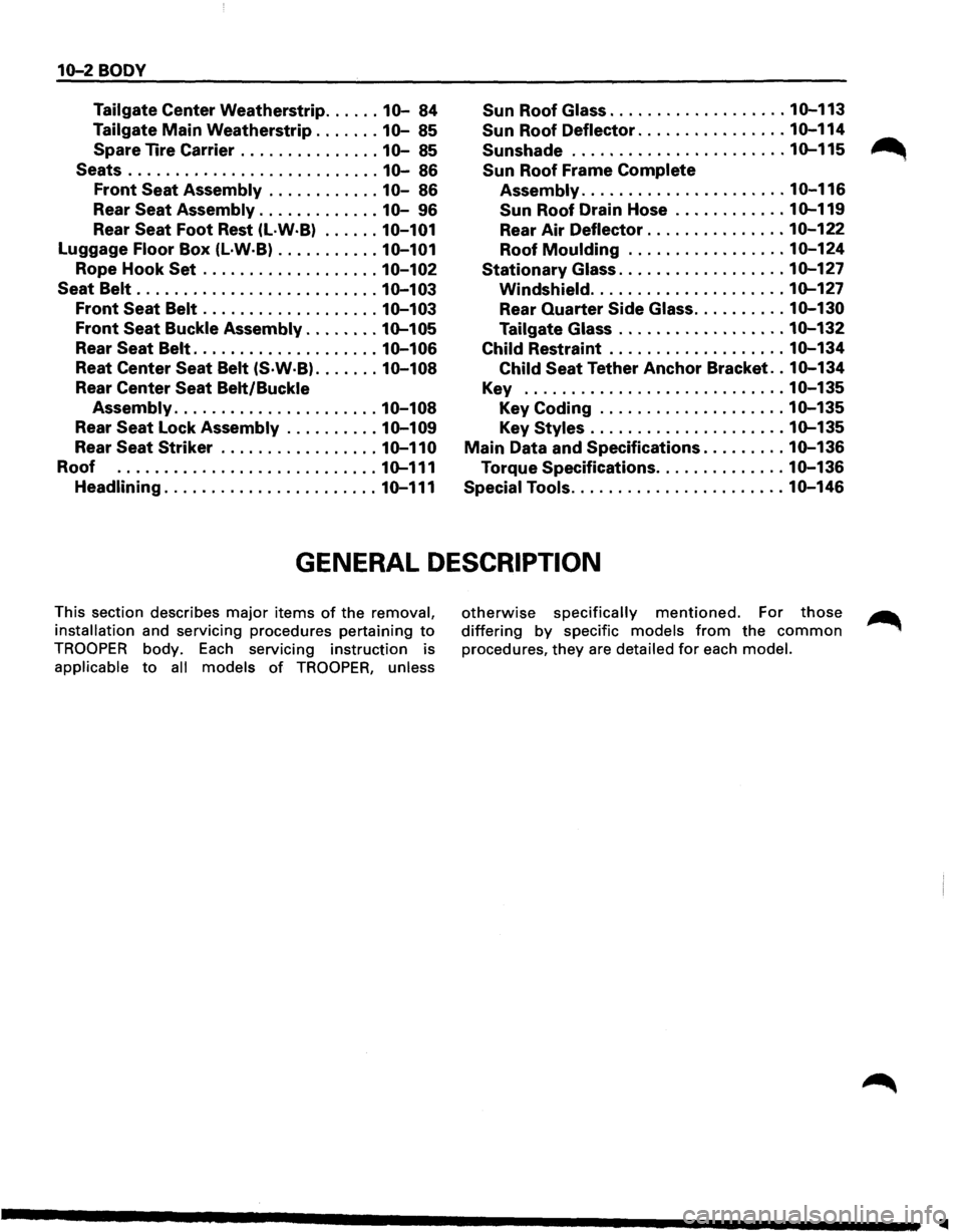
10-2 BODY
Tailgate Center Weatherstrip ...... 10-84 Sun Roof Glass ................... 10-113
Tailgate Main Weatherstrip ....... 10-85
Spare Tire Carrier
............... 10-85
Sun Roof Deflector ................ 10-114
Sunshade ....................... 10-115 ~
Seats ........................... 10-86 Sun Roof Frame Complete
Front Seat Assembly ............ 10-86 Assembly ...................... 10-116
Rear Seat Assembly ............. 10-96 Sun Roof Drain Hose ............ 10-119
Rear Seat Foot Rest (L·W·B) ...... 10-101 Rear Air Deflector ............... 10-122
Luggage Floor Box (L·W·B) ........... 10-101 Roof Moulding ................. 10-124
Rope Hook Set ................... 10-102 Stationary Glass .................. 10-127
Seat
Belt .......................... 10-103 Windshield ..................... 10-127
Front Seat Belt ................... 10-103 Rear Quarter Side Glass .......... 10-130
Front Seat Buckle Assembly ........ 10-105 Tailgate Glass .................. 10-132
Rear Seat Belt .................... 10-106 Child Restraint ................... 10-134
Reat Center Seat Belt (S·W·B) ....... 10-108 Child Seat Tether Anchor Bracket .. 10-134
Rear Center Seat Belt/Buckle Key ............................ 10-135
Assembly ...................... 10-108 Key
Coding .................... 10-135
Rear Seat Lock Assembly .......... 10-109 Key Styles ..................... 10-135
Rear Seat Striker ................. 10-110 Main Data and Specifications ......... 10-136
Roof ............................ 10-111 Torque Specifications .............. 10-136
Headlining ....................... 10-111 Special Tools ....................... 10-146
GENERAL DESCRIPTION
This section describes major items of the removal,
installation
and servicing procedures pertaining to
TROOPER body. Each servicing instruction is
applicable to all models of TROOPER, unless
otherwise specifically mentioned. For those
differing by specific models from the common
procedures, they are detailed for each model.
..
Page 1805 of 1928
BODY 16-47
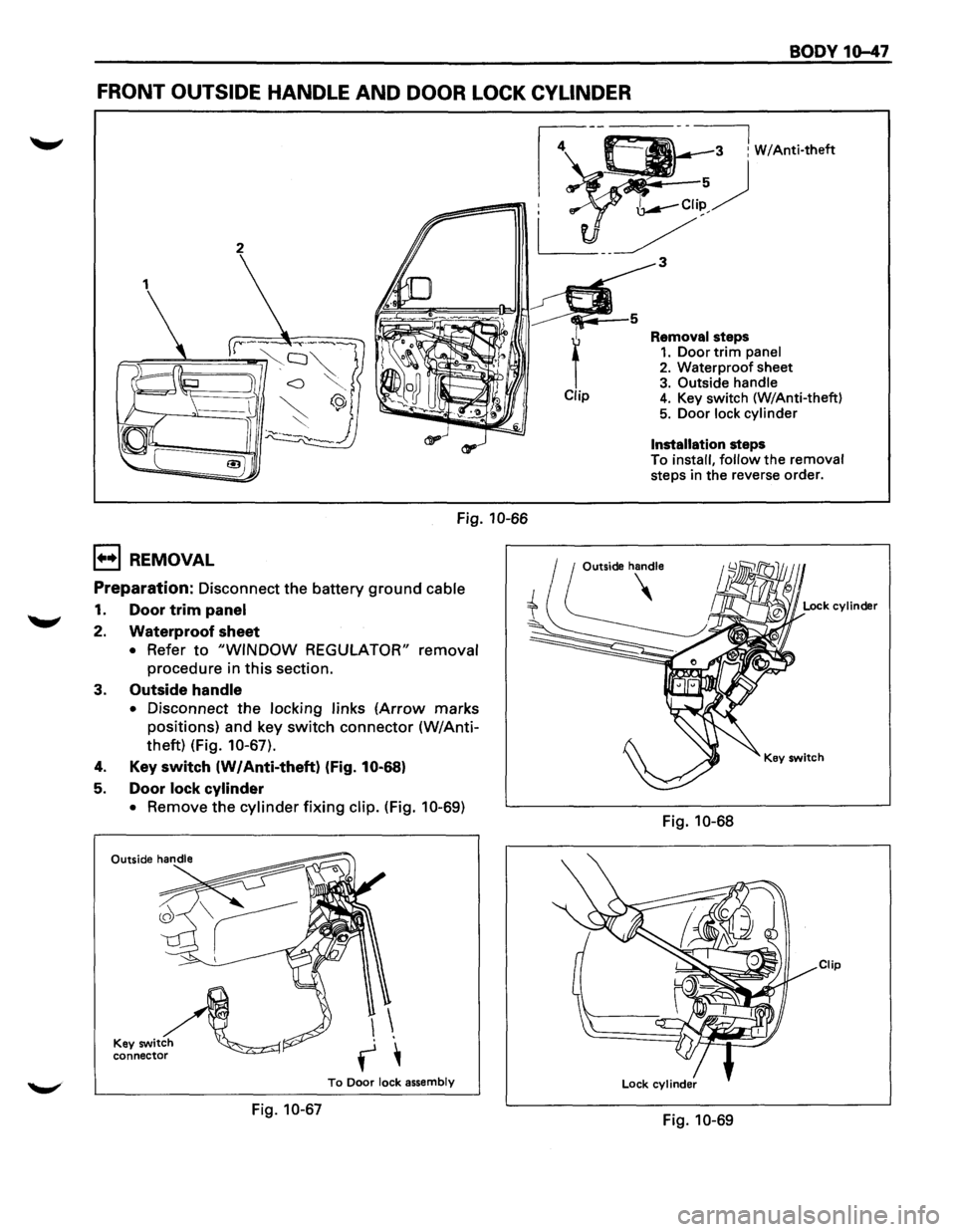
FRONT OUTSIDE HANDLE AND DOOR LOCK CYLINDER
Fig. 10-66
1+•1 REMOVAL
Preparation: Disconnect the battery ground cable
1. Door trim panel
2. Waterproof sheet
• Refer to "WINDOW REGULATOR" removal
procedure in this section.
3. Outside handle
• Disconnect the locking links (Arrow marks
positions) and key
switch connector (W/Anti
theft) (Fig. 10-67).
4. Key switch (W/Anti-theft) (fig. 10-68)
5. Door lock cylinder
• Remove the cylinder fixing clip. (Fig. 10-69)
K~~'~ connector
To Door lock assembly
Fig. 10-67
Installation steps
To install, follow the removal steps in the reverse order.
Outside handle
Fig. 10-68
Clip
Fig. 10-69
Page 1806 of 1928
10-48 BODY
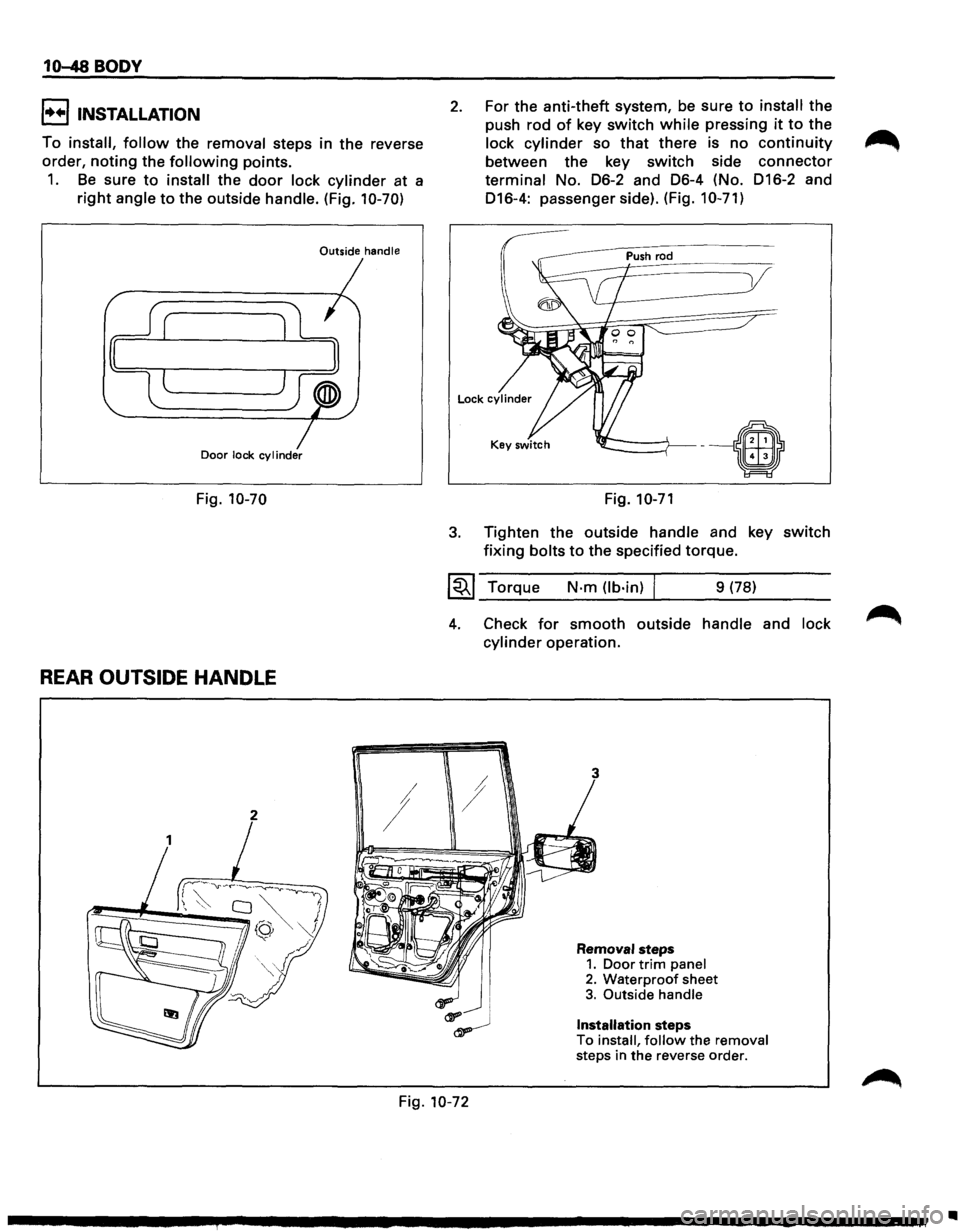
I••! INSTALLATION
To install, follow the removal steps in the reverse
order,
noting the following points.
1. Be sure to install the door lock cylinder at a
right angle to the outside handle. (Fig. 10-70)
Outside handle
Door lock cylinder
Fig. 10-70
REAR OUTSIDE HANDLE
2 I
2. For the anti-theft system, be sure to install the
push rod
of key switch while pressing it to the
lock cylinder so that there is no continuity
between the key switch side connector
terminal No. 06-2 and 06-4 (No. 016-2 and
016-4: passenger side). (Fig.
10-71)
3.
Fig. 10-71
Tighten the outside handle and key switch
fixing bolts to the specified torque.
~~~ Torque N·m (lb·in) j 9 (78)
4. Check for smooth outside handle and lock
cylinder operation.
!
Removal steps 1. Door trim panel 2. Waterproof sheet 3. Outside handle
Installation steps To install, follow the removal
steps in the reverse order.
Fig. 10-72
•
Page 1838 of 1928
10-80 BODY
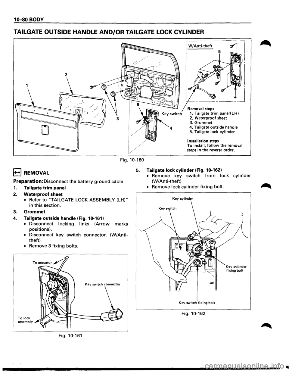
TAILGATE OUTSIDE HANDLE AND/OR TAILGATE LOCK CYLINDER
1
Fig. 10-160
I W/A~ti-theft
I
Removal steps
1. Tailgate trim panei(LH)
2. Waterproof sheet
3. Grommet
4.
Tailgate outside handle 5. Tailgate lock cylinder
Installation steps
To install, follow the removal
steps in the reverse order.
1••1 REMOVAL 5. Tailgate lock cylinder (fig. 10-162)
Preparation: Disconnect the battery ground cable
1. Tailgate trim panel
2. Waterproof sheet
• Refer to "TAILGATE LOCK ASSEMBLY (LH)"
in
this section.
3. Grommet
4. Tailgate outside handle (Fig. 10-161)
•
Disconnect locking links (Arrow marks
positions).
• Disconnect key switch connector. (W/Anti
theft)
• Remove 3 fixing bolts.
To lock assembly
Fig. 10-161
• Remove key switch from lock cylinder
(W/Anti-theft)
• Remove lock cylinder fixing bolt.
Key cylinder
Key switch fixing bolt
Fig. 10-162
Key cylinder fixing bolt
..
Page 1839 of 1928
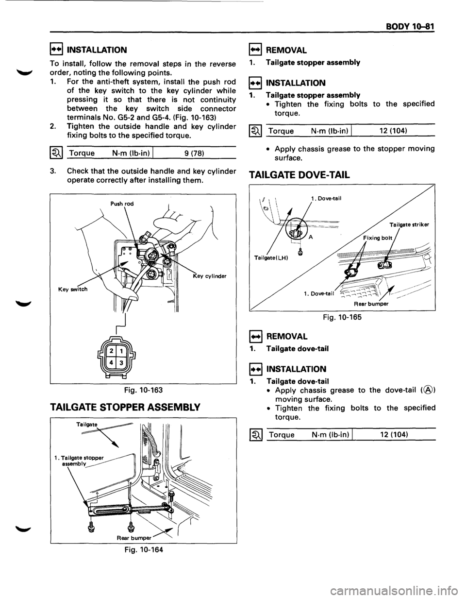
I••IINSTALLATION
To install, follow the removal steps in the reverse
order,
noting the following points.
1. For the anti-theft system, install the push rod
of the key switch to the key cylinder while
pressing it so that there is not continuity
between the key switch side connector
terminals No. GS-2 and GS-4. (Fig. 10-163)
2. Tighten the outside handle and key cylinder
fixing bolts to the specified torque.
~~~ Torque N·m (lb·in) I 9 (78)
B REMOVAL
1. Tailgate stopper assembly
I••! INSTALLATION
1. Tailgate stopper assembly
• Tighten the fixing bolts
torque.
~~~ Torque N·m (lb·in) I
BODY 10-81
to the specified
12 (104)
•
Apply chassis grease to the stopper moving
surface.
3. Check that the outside handle and key cylinder TAILGATE DOVE-TAIL
operate correctly after installing them.
Fig.
10-163
TAILGATE STOPPER ASSEMBLY
T~
Fig. 10-164
1. Dove-tail
Tailgate
striker
Tailgate( LH)
1. Dove-tail
Fig. 10-165
1••1 REMOVAL
1. Tailgate dove-tail
I••IINSTALLATION
1. Tailgate dove-tail
• Apply chassis grease to the dove-tail (@)
moving surface.
• Tighten the fixing bolts to the specified
torque.
~~~ Torque N·m Ob·in) I 12 (104)
Page 1893 of 1928
BODY 1Q-135
KEY
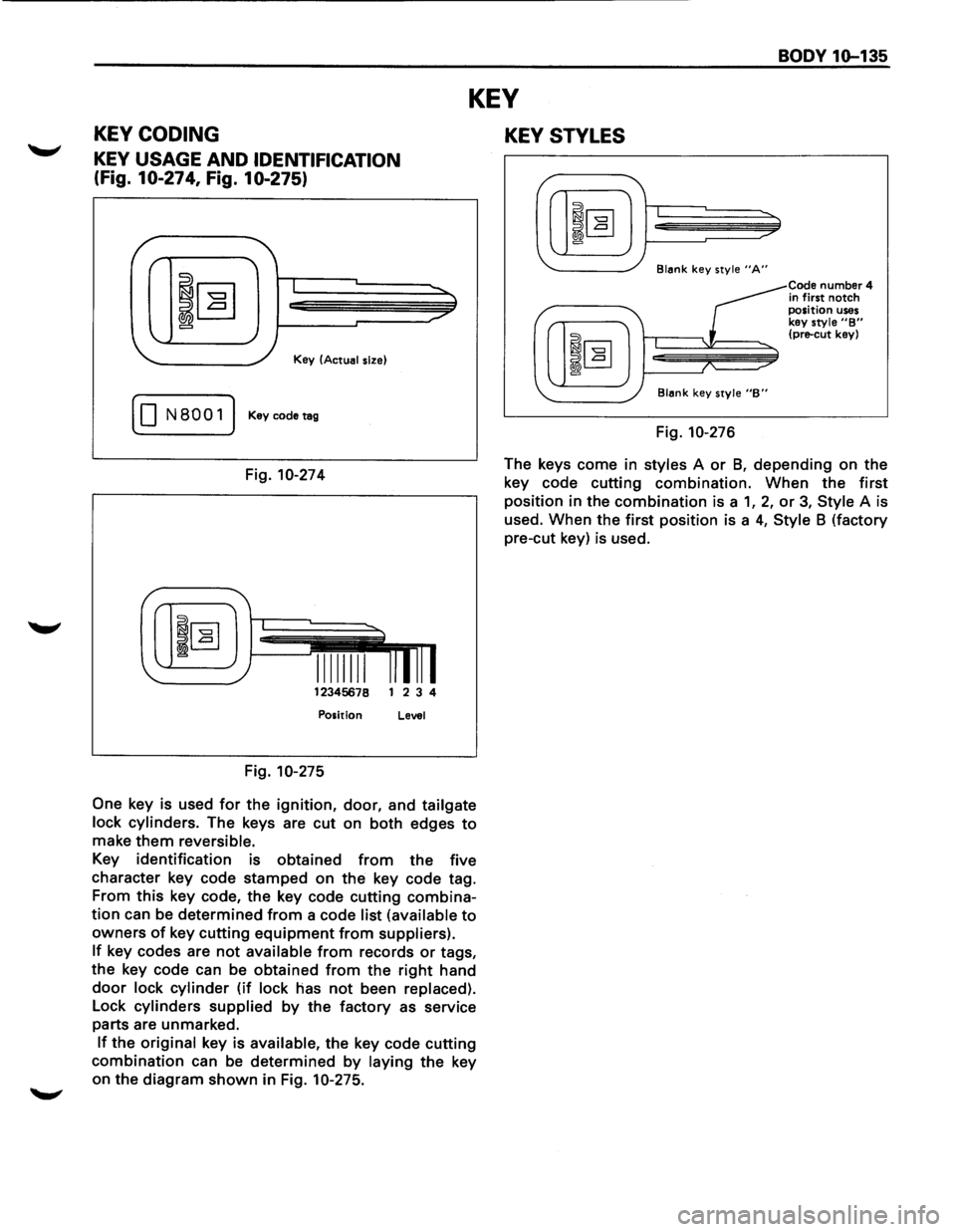
KEY CODING
KEY USAGE AND IDENTIFICATION
(Fig. 10-274, Fig. 10-275)
I
Key (Actual size)
( 0 N8001) Keycodetag
Fig. 10-274
12345678 1 2 3 4
Position Level
Fig. 10-275
One
key is used for the ignition, door, and tailgate
lock cylinders.
The keys are cut on both edges to
make them reversible.
Key identification is obtained from the five
character key code stamped on
the key code tag.
From
this key code, the key code cutting combina
tion can be determined from a code list (available to
owners of key cutting equipment from suppliers).
If key codes are not available from records or tags,
the key code can be obtained
from the right hand
door lock cylinder (if lock has not been replaced).
Lock cylinders supplied by the factory as service
parts are unmarked.
If the original key is available, the key code cutting
combination can be determined by laying the key
on the diagram
shown in Fig. 10-275.
KEY STYLES
Blank key style "A"
Blank key style "B"
Fig. 10-276
Code number 4
in first notch position uses key style "B" (pre-cut key)
The keys come in styles A or 8, depending on the
key code cutting combination. When the
first
position in the combination is a 1, 2, or 3, Style A is
used. When the
first position is a 4, Style 8 (factory
pre-cut key) is used.