ignition ISUZU TROOPER 1995 Owners Manual
[x] Cancel search | Manufacturer: ISUZU, Model Year: 1995, Model line: TROOPER, Model: ISUZU TROOPER 1995Pages: 1928
Page 690 of 1928
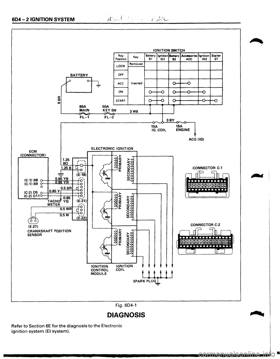
604-2 IGNITION SYSTEM
IGNITION SWITCH
Key
Key Battery
Ignition Battery Acc111ories Ignition
Starter Position 81 IG1 82 ACC IG2 ST
LOCK Removed
BATTERY OFF
/'1 ~ o-
~ Inserted ...... {) ACC ..., -
ON ...... ..... ...... ...... ...... ~ -.....
a: ...... -lXI START Q II) '-' '-' ...., ,_,
BOA 50 A
I 1 MAIN K~YSW 3WB
FL-1 FL-2 3BY -15A 15A IG.COIL ENGINE
ACG (IG)
ELECTRONIC
IGNITION ECM (CONNECTOR) > 1.25 r--""
~~ ~~ BO o""' I
~
1.25 B rrvl -~~ ' f"--~ CONNECTOR C-1
_l_ .... __ .J ~~ c1 mp Shr (E-18)
(C-1) B8 0.85 VB ,, ... , ~~ R!'i YR I I Cl.lo
I !ita lui (C-1) 89 I 0 0.5 BR d 0: IBIBIIIINIBI111Io
(C-2) 05 0.85Y "'I I I > ---(C-2) 011 I
I
)+ 0.85 '-'I a:
~~ ,_, <( TACHO YG (E-21)
~
;;!] METER ,:. .... , a: ~~ 0.5WR q 0! 0... ~~
0.5W I ~$ ... _, ~0 c ( (E-22)
(E-27) CONNECTOR C-2
CRANKSHAFT POSITION .::::> rL
r;::::l enD. .-SENSOR I~ ~~
~ ~ ~~ rt~·· IC4 IT>TiiTiil
f §~
~g l CIJ 0::
·~'l
IGNITION IGNITION CONTROL
COIL MODULE tii1it SPARK PLU
DIAGNOSIS
Refer to Section 6E for the diagnosis to the Electronic
ignition system (EI system).
•
Page 691 of 1928
![ISUZU TROOPER 1995 Owners Manual IGNITION SYSTEM 604 - 3
ON-VEHICLE SERVICE
SPARK PLUG WIRES
EJ REMOVAL
Preparation
• Disconnect battery ground cable.
1. Spark plug wires (Fig. 604-2)
Fig. 6D4-2
(1!] INSPECTION AND REPAIR](/img/61/57183/w960_57183-690.png "ISUZU TROOPER 1995 Owners Manual IGNITION SYSTEM 604 - 3
ON-VEHICLE SERVICE
SPARK PLUG WIRES
EJ REMOVAL
Preparation
• Disconnect battery ground cable.
1. Spark plug wires (Fig. 604-2)
Fig. 6D4-2
(1!] INSPECTION AND REPAIR")
IGNITION SYSTEM 604 - 3
ON-VEHICLE SERVICE
SPARK PLUG WIRES
EJ REMOVAL
Preparation
• Disconnect battery ground cable.
1. Spark plug wires (Fig. 604-2)
Fig. 6D4-2
(1!] INSPECTION AND REPAIR
Check the high tension cable for insulation. Check
terminals for corrosion or damage, and replace as
necessary.
Measuring resistance of spark plug wires (kQ)
Spare plug wires SOHC DOHC
No.1 cable 6.4-14.9 6.2-14.2
No.2 cable 5.7-13.1 7.2-16.7
No.3 cable 6.2-14.4 6.5-14.9
No.4 cable 5.8-13.3 6.8-15.8
No.5 cable 6.4-14.9 6.9-16.0
No.6 cable 6.9-16.0 6.3-14.5
Measure resistance
of spark plug wires, and replace
the cable if its value exceeds the standard. (Fig. 6D4-
3)
Fig. 6D4-3
B INSTALLATION
1. Spark plug wires
• Connect ignition coils and spark plugs with
spark plug wires respectively. Match each
number (cylinder No.) marked on the ignition
coil with that on spark plug wire, and connect
each spark
plug for the cylinder. (Fig. 6D4-4)
LH bank
y Front
#4-
#1--
1®®®1
RH Bank
Connecting Position of Spark plug wire
Fig. 6D4-4
• Connect battery ground cable.
"f CAUTION
Do not cross, twist or pull the spark plug wires.
SPARK PLUG
EJ REMOVAL
1. Spare plug wires
2. Spark plugs (Fig. 604-5)
Page 692 of 1928
604-4 IGNITION SYSTEM
Fig. 604A-5
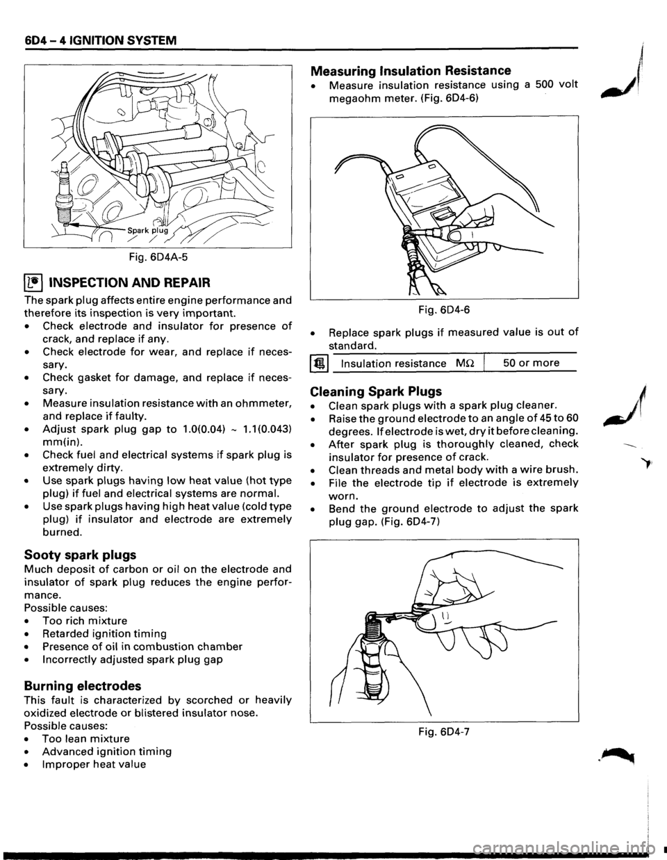
~ INSPECTION AND REPAIR
The spark plug affects entire engine performance and
therefore its inspection is very important.
• Check electrode and insulator for presence of
crack, and replace if any.
• Check electrode for wear, and replace if neces
sary.
• Check gasket for damage, and replace if neces
sary.
• Measure insulation resistance with an ohmmeter,
and replace if faulty.
• Adjust spark plug gap to 1.0(0.04) -1.1 (0.043)
mm(in).
• Check fuel and electrical systems if spark plug is
extremely dirty.
• Use spark plugs having low heat value (hot type
plug) if fuel and electrical systems are normal.
• Use spark plugs having high heat value (cold type
plug) if insulator and electrode are extremely
burned.
Sooty spark plugs
Much deposit of carbon or oil on the electrode and
insulator of spark plug reduces the engine perfor
mance.
Possible causes:
• Too rich mixture
• Retarded ignition timing
• Presence of oil in combustion chamber
• Incorrectly adjusted spark plug gap
Burning electrodes
This fault is characterized by scorched or heavily
oxidized electrode or blistered insulator nose.
Possible causes:
• Too lean mixture
• Advanced ignition timing
• Improper heat value
Measuring Insulation Resistance
• Measure insulation resistance using a 500 volt
megaohm meter. (Fig. 604-6)
Fig.
604-6
• Replace spark plugs if measured value is out of
standard.
I @!.j Insulation resistance MQ 50 or more
Cleaning Spark Plugs
• Clean spark plugs with a spark plug cleaner.
• Raise the ground electrode to an angle of 45 to 60
degrees. If electrode is wet, dry it before cleaning.
• After spark plug is thoroughly cleaned, check
insulator for presence of crack.
• Clean threads and metal body with a wire brush.
• File the electrode tip if electrode is extremely
worn.
• Bend the ground electrode to adjust the spark
plug gap. (Fig. 604-7)
Fig. 604-7
•
Page 693 of 1928
[!!) INSTALLATION
2. Spark plugs
• Tighten spark plugs to the specified torque.
1. Spark plug wires
• Connect high tension cables to correct termi
nals respectively.
~~~ Torque N·m (lb·ft) I
ELECTRONIC IGNITION (EI)
ASSEMBLY
EJ REMOVAL
Preparation
• Disconnect battery ground cable
1. Spark plug wires
2. Wiring connectors
18 (13)
• Disconnect connectors on Engine Control
Module (ECM), power supply and crank angle
sensor.
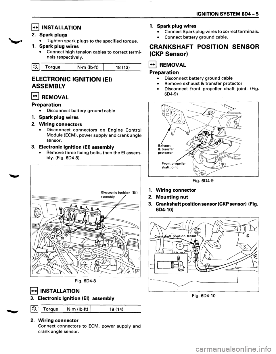
3. Electronic Ignition (EI) assembly
• Remove three fixing bolts, then the El assem
bly. (Fig. 6D4-8)
Fig. 6D4-8
E]INSTALLATION
Electronic Ignition (Ell assembly
3. Electronic Ignition (EI) assembly
~~~ Torque N·m (lb·ftl I 19 (14)
2. Wiring connector
Connect connectors to ECM, power supply and
crank
angle sensor.
IGNITION SYSTEM 604-5
1. Spark plug wires
• Connect Spark plug wires to correct terminals.
• Connect battery ground cable.
CRANKSHAFT POSITION SENSOR
(CKP Sensor)
E) REMOVAL
Preparation
• Disconnect battery ground cable
•
Remove exhaust & transfer protector
• Disconnect front propeller shaft joint. (Fig.
6D4-9)
Fig. 6D4-9
1. Wiring connector
2. Mounting nut
3. Crankshaft position sensor (CKP sensor) (Fig.
604-10)
Fig. 6D4-10
Page 694 of 1928
604-6 IGNITION SYSTEM
B INSTALLATION
3. Crankshaft Position Sensor (CKP sensor)
• Install crankshaft position sensor into the cyl
inder block.
1~1 Before installation, apply small amount of en
gine oil to the 0-ring.
~~~ Torque N-m (lb-in) I 10 (87)
2. Mounting bolt
• Tighten the bolt to the specified torque.
~~~ Torque N-m (lb·ft) I 63 (46)
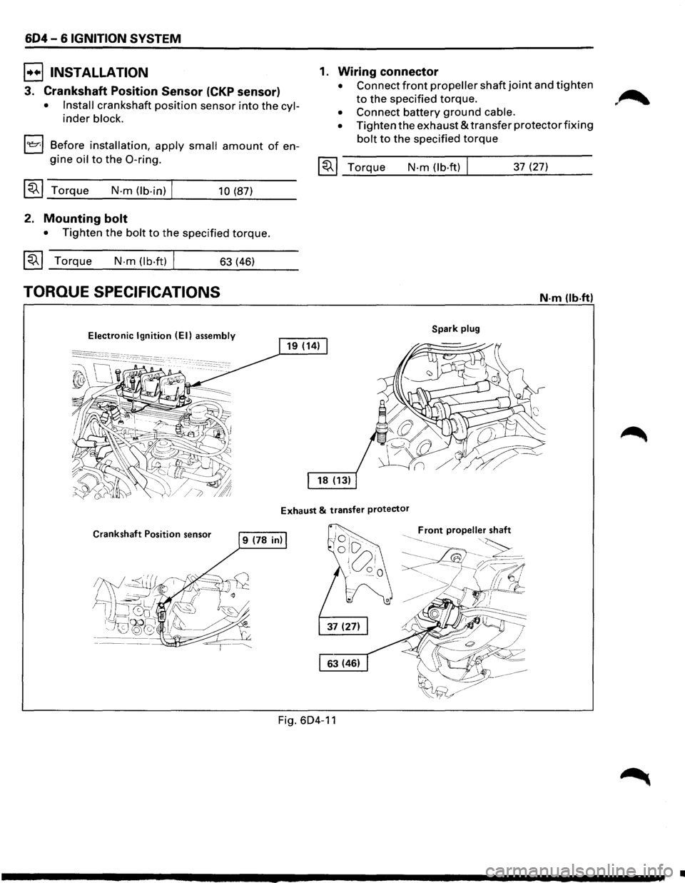
TORQUE SPECIFICATIONS
Electronic Ignition (EI) assembly
1. Wiring connector
• Connect front propeller shaft joint and tighten
to the specified torque.
• Connect battery ground cable.
•
Tighten the exhaust & transfer protector fixing
bolt to the specified torque
~~~ Torque N-m (lb·ft) 37 (27)
N·m (lb·ftl
Spark plug
Exhaust & transfer protector
Crankshaft Position sensor
Fig. 604-11
•
Page 695 of 1928
IGNITION SYSTEM 604-7
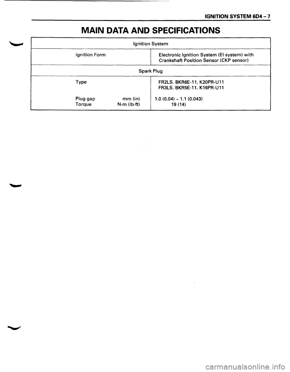
MAIN DATA AND SPECIFICATIONS
Ignition System
Ignition Form Electronic Ignition System (EI system) with
Crankshaft Position Sensor (CKP sensor)
Spark
Plug
Type FR2LS. BKRSE-11. K20PR-U 11
FR3LS. BKRSE-11. K 16PR-U 11
Plug gap mm (in) 1.0 (0.04) -1.1 (0.043)
Torque N·m Ob·ft) 19 (14)
Page 698 of 1928
6E2-2 DRIVEABILITY AND EMISSIONS
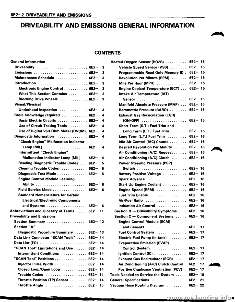
DRIVEABILITV AND EMISSIONS GENERAL INFORMATION
CONTENTS
General Information
Driveability ....................... .
Emissions
........................ .
Maintenance
Schedule .............. .
Introduction ...................... .
Electronic Engine
Control .......... .
What This Section Contains ........ .
Blocking Drive Wheels
Visual/Physical
Underhood Inspection
6E2-3
6E2-3
6E2-3
6E2-3
6E2-3
6E2-3
6E2-3
6E2-3
Basic
Knowledge required . . . . . . . . . . . . 6E2-4
Basic Electric Circuits . . . . . . . . . . . . . .
6E2-4
Use
of Circuit Testing Tools . . . . . . . . . 6E2-4
Use
of Digital Volt-Ohm Meter (DVOM). 6E2-4
Diagnostic
Information . . . . . . . . . . . . . . . 6E2-4
"Check Engine" Malfunction Indicator
Lamp (MIL) . . . . . . . . . . . . . . . . . . . . 6E2-4
Intermittent "Check Engine"
Malfunction Indicator Lamp (MIL) . . 6E2-4
Reading Diagnostic
Trouble Codes . . . 6E2-5
Clearing
Trouble Codes . . . . . . . . . . . . 6E2-5
Diagnostic Test
Mode .............. 6E2-5
Engine Control
Module Learning
Ability . . . . . . . . . . . . . . . . . . . . . . . . 6E2-6
Field
Service Mode . . . . . . . . . . . . . . . . 6E2-6
Standard Nomenclature
for Certain
Electrical/Electronic
Components
and Systems . . . . . . . . . . . . . . . . . . . 6E2-6
Abbreviations and Glossary of Terms ..... 6E2-11
Driveability and Emissions
Section Summary ................... 6E2-12
Section .,. A"
Diagnostic Procedure Summary ...... 6E2-13
Data Link Connector
"SCAN Tools" ..... 6E2-14
Data
List (FO) ...................... 6E2-14
"SCAN Tool" Limitations and Use ...... 6E2-14
Intermittent Conditions ............ 6E2-14
"SCAN Tool" Positions ............... 6E2-14
Injector Pulse Width ............... 6E2-14
Closed Loop/Open Loop . . . . . . . . . . . .
6E2-14
Trouble Codes ................... 6E2-14
Throttle Position (TP) Sensor . . . . . . . . 6E2-14
Throttle Angle . . . . . . . . . . . . . . . . . . . 6E2-15 Heated
Oxygen
Sensor (H02S)
Vehicle Speed Sensor (VSS) ....... .
Programmable Read Only Memory ID .
Revolution
Per Minute (RPM) ...... .
Mile Per Hour (MPH) ............. .
Engine
Coolant Temperature (ECT) .. .
Intake Air Temperature (IAT)
Sensor
...................... .
Manifold Absolute Pressure (MAP) .. .
Barometric Pressure (BARO) ....... .
Exhaust Gas Recirculation
(EGR)
(ON/OFF) .................... .
Short Term (S.T.) Fuel Trim and
Long Term
(LT.) Fuel Trim ...... .
Long Term
(LT.) Fuel Trim ........ .
Idle Air Control (lAC) Counts ....... .
Desired Revolution
Per Minute ..... .
Air Conditioning (A/C) Request ..... .
Air Conditioning (A/C) Clutch ...... .
Power Steering Pressure (PSP)
Switch ...................... .
Battery Positive Voltage .......... .
Spark Advance .................. .
Start Up Engine Coolant .......... .
Engine
Speed (RPM) ............. .
Fuel Trim Enable ................ .
Air/Fuel Ratio .................. .
Induction Air Control ............. .
Section B -Driveability Symptoms ... .
Section C -Component Systems .... .
Engine
Control Module (ECM)
and
Sensors .................. .
Fuel Control System ............. .
Electric
Fuel Pump (in-tank) ....... .
Evaporative Emission
(EVAP)
Control System ................ .
Ignition Control (IC) .............. .
Exhaust Gas Recirculator
(EGR) .... .
Air Conditioning (A/C) Clutch Control .
Positive Crankcase Ventilation (PCV) .
Tools Needed
to Service the System .... .
General Specifications
............... .
Vacuum Hose Routing Diagram
........ .
6E2-15
6E2-15
6E2-15
6E2-15
6E2-15
6E2-15
6E2-15
6E2-15
6E2-15
6E2-15
6E2-15
6E2-16
6E2-16
6E2-16
6E2-16
6E2-16
6E2-16
6E2-16
6E2-16
6E2-16
6E2-16
6E2-16
6E2-16
6E2-16
6E2-16
6E2-16
6E2-17
6E2-17
6E2-17
6E2-17
6E2-17
6E2-17
6E2-17
6E2-17
6E2-18
6E2-21
6E2-22
~
... ...
•
Page 699 of 1928
---
DRIVEABILITV AND EMISSIONS 6E2-3
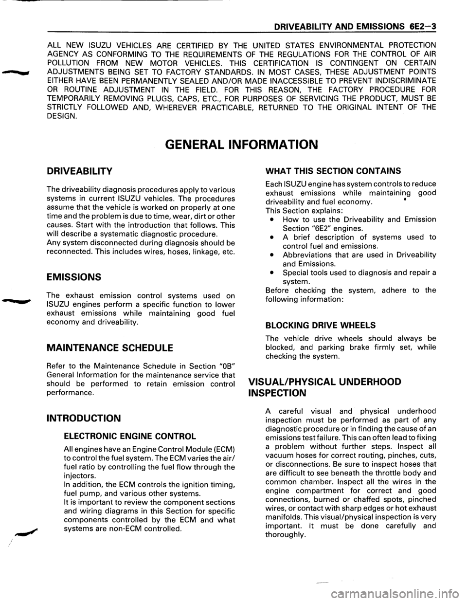
ALL NEW ISUZU VEHICLES ARE CERTIFIED BY THE UNITED STATES ENVIRONMENTAL PROTECTION
AGENCY AS CONFORMING TO THE REQUIREMENTS OF THE REGULATIONS FOR THE CONTROL OF AIR
POLLUTION FROM NEW MOTOR VEHICLES. THIS CERTIFICATION IS CONTINGENT ON CERTAIN
ADJUSTMENTS BEING SET TO FACTORY STANDARDS. IN MOST CASES, THESE ADJUSTMENT POINTS
EITHER HAVE BEEN PERMANENTLY SEALED AND/OR MADE INACCESSIBLE TO PREVENT INDISCRIMINATE
OR ROUTINE ADJUSTMENT IN THE FIELD. FOR THIS REASON, THE FACTORY PROCEDURE FOR
TEMPORARILY REMOVING PLUGS, CAPS, ETC., FOR PURPOSES OF SERVICING THE PRODUCT, MUST BE
STRICTLY FOLLOWED AND, WHEREVER PRACTICABLE, RETURNED TO THE ORIGINAL INTENT OF THE
DESIGN.
GENERAL INFORMATION
DRIVEABILITY
The driveability diagnosis procedures apply to various
systems in current
ISUZU vehicles. The procedures
assume
that the vehicle is worked on properly at one
time and the
problem is due to time, wear, dirt or other
causes.
Start with the introduction that follows. This
will describe a systematic diagnostic procedure.
Any system disconnected during diagnosis should be
reconnected. This
includes wires, hoses, linkage, etc.
EMISSIONS
The exhaust emission control systems used on
ISUZU engines perform a specific function to lower
exhaust emissions while maintaining good fuel
economy and driveability.
MAINTENANCE SCHEDULE
Refer to the Maintenance Schedule in Section "OB"
General Information for the maintenance service that
should be performed to retain emission control
performance.
INTRODUCTION
ELECTRONIC ENGINE CONTROL
All engines have an Engine Control Module (ECM)
to control the fuel system. The ECM varies the air/
fuel ratio by controlling the fuel flow through the
injectors.
In addition, the ECM controls the ignition timing,
fuel pump, and various other systems.
It is important to review the component sections
and
wiring diagrams in this Section for specific
components
controlled by the ECM and what
systems are non-ECM controlled.
WHAT THIS SECTION CONTAINS
Each ISUZU engine has system controls to reduce
exhaust emissions
while maintaining good
driveability and fuel economy. •
This Section explains:
•
How to use the Driveability and Emission
Section
"6E2" engines.
• A brief description of systems used to
control fuel and emissions.
• Abbreviations that are used in Driveability
and Emissions.
• Special tools used to diagnosis and repair a
system.
Before checking the
system, adhere to the
following information:
BLOCKING DRIVE WHEELS
The vehicle drive wheels should always be
blocked, and parking brake firmly set, while
checking the system.
VISUAL/PHYSICAL UNDERHOOD
INSPECTION
A careful visual and physical underhood
inspection must
be performed as part of any
diagnostic procedure
or in finding the cause of an
emissions test failure. This can often lead to fixing
a
problem without further steps. Inspect all
vacuum hoses for correct routing, pinches, cuts,
or disconnections. Be sure to inspect hoses that
are
difficult to see beneath the throttle body and
common chamber.
Inspect all the wires in the
engine
compartment for correct and good
connections, burned or chaffed spots, pinched
wires, or contact with sharp edges or hot exhaust
manifolds. This visual/physical inspection is very
important. It must be done carefully and
thoroughly.
Page 701 of 1928
......, .., LU
READING DIAGNOSTIC TROUBLE CODES
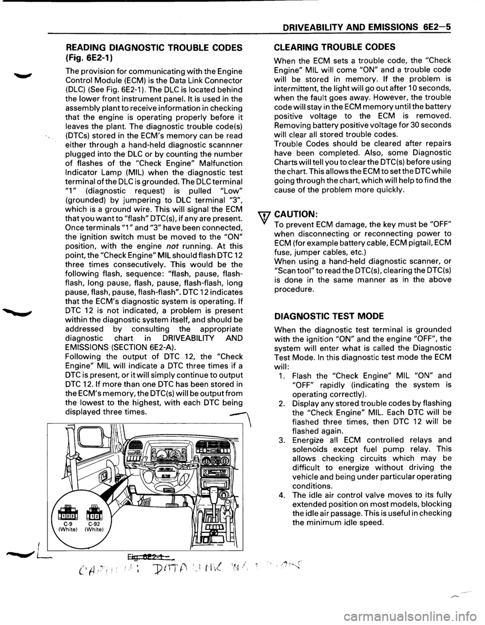
(Fig. 6E2-1)
The provision for communicating with the Engine
Control Module (ECM) is the Data Link Connector
(DLC) (See Fig. 6E2-1 ). The DLC is located behind
the
lower front instrument panel. It is used in the
assembly plant
to receive information in checking
that the engine is operating properly before it
leaves the plant. The diagnostic trouble code(s)
(DTCs) stored in the ECM's memory can be read
either through a hand-held diagnostic scannner
plugged into the
DLC or by counting the number
of flashes of the "Check Engine" Malfunction
Indicator Lamp (MIL) when the diagnostic test
terminal
ofthe DLC is grounded. The DLC terminal
"1" (diagnostic request) is pulled "Low"
(grounded) by jumpering to DLC terminal "3",
which is a ground wire. This will signal the ECM
that you want to "flash" DTC(s), if any are present.
Once terminals "1" and "3" have been connected,
the ignition switch
must be moved to the "ON"
position, with the engine not running. At this
point, the
"Check Engine" MIL should flash DTC 12
three times consecutively. This
would be the
following flash, sequence: "flash, pause, flash
flash,
long pause, flash, pause, flash-flash, long
pause, flash, pause, flash-flash". DTC 12 indicates
that the ECM's diagnostic system is operating.
If
DTC 12 is not indicated, a problem is present
within the diagnostic system itself, and should be
addressed
by consulting the appropriate
diagnostic chart in
DRIVEABILITY AND
EMISSIONS (SECTION 6E2-A).
Following the output of DTC 12, the "Check
Engine" MIL
will indicate a DTC three times if a
DTC is present, or it will simply continue to output
DTC 12. If more than one DTC has been stored in
the
ECM's memory, the DTC(s) will be outputfrom
the lowest to the highest, with each DTC being
displayed three times.
--
Eig tU!2-1-...
DRIVEABILITY AND EMISSIONS 6E2-5
CLEARING TROUBLE CODES
When the ECM sets a trouble code, the "Check
Engine" MIL
will come "ON" and a trouble code
will be stored in memory. If the problem is
intermittent, the light
will go out after 10 seconds,
when the fault goes away. However, the trouble
code
will stay in the ECM memory until the battery
positive voltage
to the ECM is removed.
Removing battery positive voltage
for 30 seconds
will clear all stored trouble codes.
Trouble
Codes should be cleared after repairs
have been completed. Also, some Diagnostic
Charts will tell you to clear the DTC(s) before using
the chart. This
allows the ECM tosetthe DTCwhile
going through the chart, which will help to find the
cause
of the problem more quickly.
wcAUTION:
• To prevent ECM damage, the key must be "OFF"
when disconnecting or reconnecting power to
ECM (for example battery cable, ECM pigtail, ECM
fuse, jumper cables, etc.)
When using a hand-held diagnostic scanner,
or
"Scan tool" to read the DTC(s), clearing the DTC(s)
is done in the same manner as in the above
procedure.
DIAGNOSTIC TEST MODE
When the diagnostic test terminal is grounded
with the ignition "ON" and the engine "OFF", the
system
will enter what is called the Diagnostic
Test Mode.
In this diagnostic test mode the ECM
will:
1. Flash the "Check Engine" MIL "ON" and
"OFF" rapidly (indicating the system is
operating correctly).
2. Display any stored trouble codes by flashing
the
"Check Engine" MIL. Each DTC will be
flashed three times, then
DTC 12 will be
flashed again.
3. Energize all ECM controlled relays and
solenoids except
fuel pump relay. This
allows checking circuits which may be
difficult to energize without driving the
vehicle and being under particular operating
conditions.
4. The idle air control valve moves to its fully
extended position on most models, blocking
the
idle air passage. This is useful in checking
the
minimum idle speed.
Page 703 of 1928
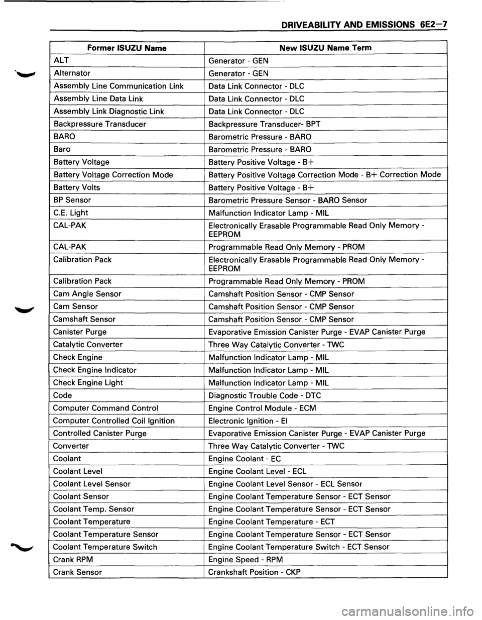
DRIVEABILITY AND EMISSIONS 6E2-7
Former ISUZU Name New ISUZU Name Term
ALT Generator -GEN
Alternator
Generator -GEN
Assembly Line Communication Link
Data Link Connector -DLC
Assembly Line Data Link
Data Link Connector -DLC
Assembly Link Diagnostic Link
Data Link Connector -DLC
Backpressure Transducer
Backpressure Transducer-BPT
BARO Barometric Pressure -BARO
Baro
Barometric Pressure -BARO
Battery Voltage
Battery Positive Voltage-B+
Battery Voltage Correction Mode Battery Positive Voltage Correction Mode -B+ Correction Mode
Battery Volts
Battery
Positive Voltage-B+
BP Sensor Barometric Pressure Sensor -BARO Sensor
C.E. Light
Malfunction Indicator Lamp -MIL
CAL-PAK Electronically
Erasable Programmable Read Only Memory -
EEPROM
CAL-PAK
Programmable Read Only Memory -PROM
Calibration Pack Electronically Erasable Programmable Read Only Memory -
EEPROM
Calibration Pack
Programmable Read Only Memory-PROM
Cam Angle Sensor Camshaft Position Sensor -CMP Sensor
Cam Sensor Camshaft Position Sensor -CMP Sensor
Camshaft Sensor Camshaft Position Sensor -CMP Sensor
Canister Purge Evaporative Emission Canister Purge-EVAP Canister Purge
Catalytic Converter
Three Way Catalytic Converter-TWC
Check Engine
Malfunction
Indicator Lamp -MIL
Check Engine Indicator Malfunction Indicator Lamp -MIL
Check Engine Light
Malfunction Indicator Lamp-MIL
Code Diagnostic Trouble Code -DTC
Computer Command Control Engine Control Module -ECM
Computer Controlled Coil Ignition Electronic Ignition -El
Controlled Canister Purge Evaporative Emission Canister Purge-EVAP Canister Purge
Converter Three Way Catalytic Converter -TWC
Coolant Engine Coolant -EC
Coolant Level
Engine Coolant Level -ECL
Coolant Level Sensor Engine Coolant Level Sensor -ECL Sensor
Coolant Sensor Engine Coolant Temperature Sensor -ECT Sensor
Coolant Temp. Sensor Engine Coolant Temperature Sensor-ECT Sensor
Coolant Temperature Engine Coolant Temperature -ECT
Coolant Temperature Sensor Engine Coolant Temperature Sensor-ECT Sensor
Coolant Temperature Switch Engine Coolant Temperature Switch -ECT Sensor
Crank RPM Engine Speed -RPM
Crank Sensor Crankshaft Position-CKP