ignition ISUZU TROOPER 1995 Repair Manual
[x] Cancel search | Manufacturer: ISUZU, Model Year: 1995, Model line: TROOPER, Model: ISUZU TROOPER 1995Pages: 1928
Page 502 of 1928
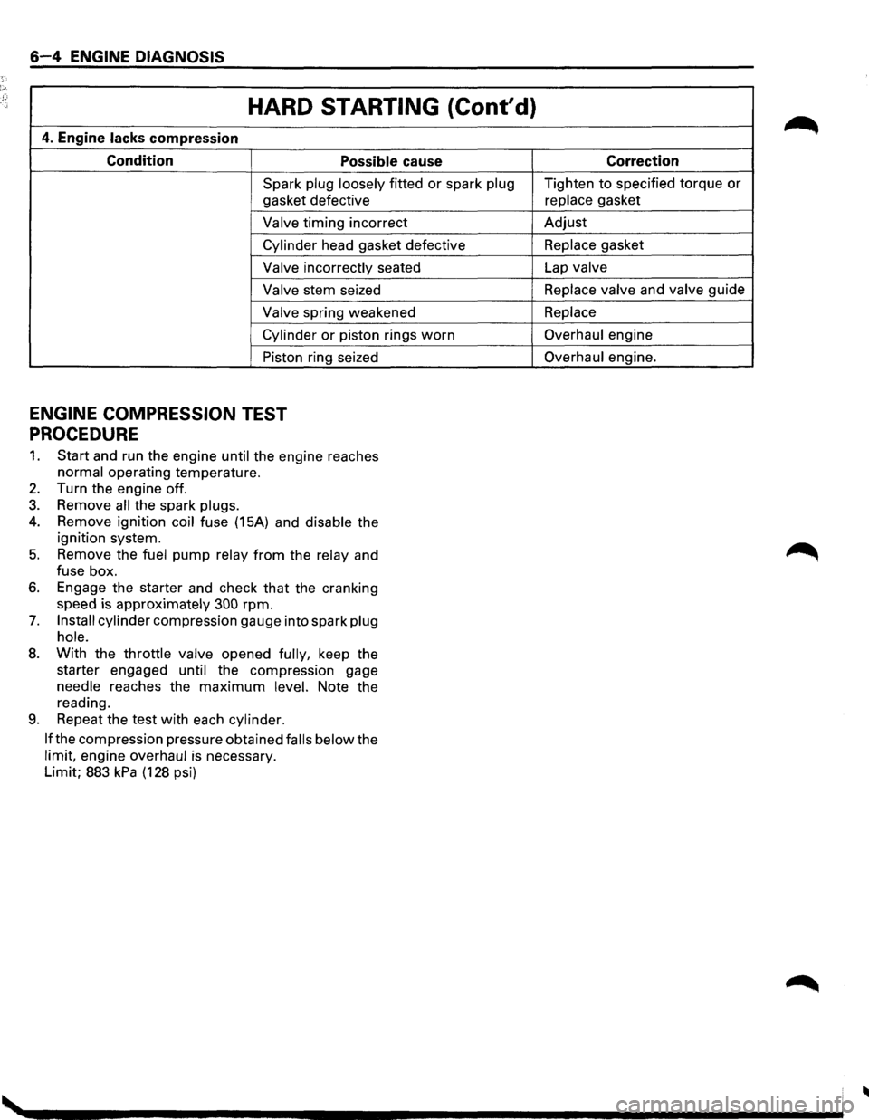
6-4 ENGINE DIAGNOSIS
HARD STARTING (Cont'd)
4. Engine lacks compression
Condition Possible cause
Spark plug loosely fitted or spark plug
gasket defective
Valve timing incorrect
Cylinder head gasket defective
Valve incorrectly seated
Valve stem seized
Valve spring weakened
Cylinder or piston rings worn
Piston ring seized
ENGINE COMPRESSION TEST
PROCEDURE
1. Start and run the engine until the engine reaches
normal operating temperature.
2. Turn the engine off.
3. Remove all the spark plugs.
4. Remove ignition coil fuse (15A) and disable the
ignition system.
5. Remove the fuel pump relay from the relay and
fuse box.
6. Engage the starter and check that the cranking
speed is approximately
300 rpm.
7. Install cylinder compression gauge into spark plug
hole.
8. With the throttle valve opened fully, keep the
starter engaged
until the compression gage
needle reaches the
maximum level. Note the
reading.
9. Repeat the test with each cylinder.
If
the compression pressure obtained falls below the
limit, engine overhaul is necessary.
Limit; 883
kPa (128 psi) Correction
Tighten
to specified torque or
replace gasket
Adjust
Replace gasket
Lap
valve
Replace valve
and valve guide
Replace
Overhaul engine
Overhaul engine.
Page 503 of 1928
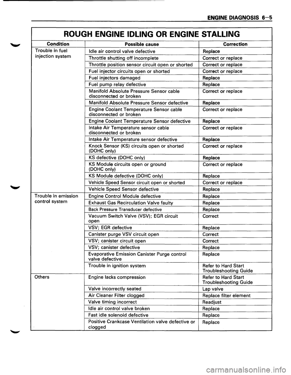
ENGINE DIAGNOSIS 6-5
ROUGH ENGINE IDLING OR ENGINE STALLING
Condition Possible cause Correction
Trouble in fuel
Idle air control valve defective Replace
injection system
Throttle shutting
off incomplete Correct or replace
Throttle position sensor circuit open
or shorted Correct or replace
Fuel injector circuits open or shorted Correct or replace
Fuel injectors damaged
Replace
Fuel pump relay defective Replace
Manifold Absolute Pressure Sensor
cable Correct or replace
disconnected
or broken
Manifold Absolute Pressure Sensor defective
Replace
Engine Coolant Temperature Sensor cable Correct
or replace
disconnected
or broken
Engine Coolant Temperature Sensor defective
Replace
Intake Air Temperature sensor cable Correct or replace
disconnected
or broken
Intake Air Temperature sensor defective
Replace
Knock Sensor
(KS) circuits open or shorted
Correct or replace
(DOHC only)
KS defective (DOHC only) Replace
KS Module circuits open or ground
Correct or replace
(DOHC only)
KS Module defective (DOHC only) Replace
Vehicle Speed Sensor circuit open or shorted
Correct or replace
Vehicle Speed Sensor defective
Replace
Trouble in emission
Engine Control Module defective
Replace
control system
Exhaust Gas Recirculation
Valve faulty
Replace
Back Pressure Transducer defective
Replace
Vacuum Switch Valve (VSV); EGR circuit
Correct
open
VSV; EGR defective Replace
Canister purge
VSV circuit open
Correct
VSV; canister circuit open
Correct
VSV; canister defective
Replace
Evaporative Emission Canister Purge control
Replace
valve defective
Trouble in ignition system
Refer
to Hard Start
Troubleshooting Guide
Others Engine lacks compression
Refer to Hard Start
Troubleshooting Guide
Valve incorrectly seated
Lap valve
Air Cleaner Filter clogged
Replace filter element
Valve timing incorrect
Readjust
Idle air control valve broken
Replace
Fast
idle solenoid defective
Replace
Positive Crankcase Ventilation valve defective
or Replace
clogged
Page 504 of 1928
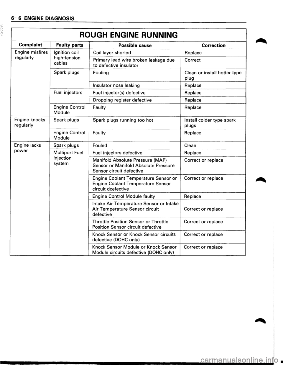
6-6 ENGINE DIAGNOSIS
ROUGH ENGINE RUNNING
Complaint
Faulty parts Possible cause Correction
Engine misfires Ignition coil
Coil layer shorted Replace
regularly
high-tension Primary lead wire broken leakage due
Correct cables to defective insulator
Spark plugs
Fouling Clean
or install hotter type
plug
Insulator
nose leaking Replace
Fuel
injectors Fuel injector(s) defective Replace
Dropping register defective Replace
Engine Control
Faulty Replace
Module
Engine knocks Spark plugs
Spark plugs running too hot Install colder type spark
regularly
plugs
Engine Control Faulty
Replace
Module
Engine lacks Spark plugs
Fouled Clean
power Multipart Fuel
Fuel injectors defective Replace
Injection Manifold Absolute Pressure (MAP)
Correct or replace system Sensor or Manifold Absolute Pressure
Sensor
circuit defective
Engine
Coolant Temperature Sensor or Correct or replace
Engine Coolant Temperature Sensor
circuit dcefective
Engine
Control Module faulty Replace
Intake
Air Temperature Sensor or Intake
Air Temperature Sensor circuit Correct or replace
defective
Throttle Position Sensor or Throttle Correct or replace
Position Sensor
circuit defective
Knock
Sensor or Knock Sensor circuits Correct or replace
defective (DOHC only)
Knock Sensor Module or Knock Sensor Correct or replace .
Module
circuits defective (DOHC only)
•
Page 506 of 1928
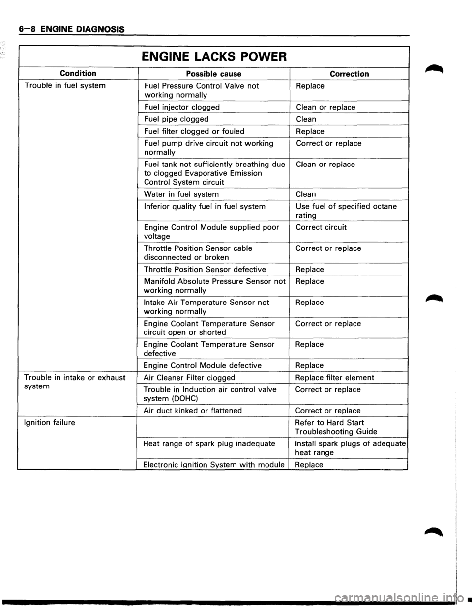
6-8 ENGINE DIAGNOSIS
ENGINE LACKS POWER
Condition
Possible cause Correction
Trouble in fuel system Fuel Pressure Control Valve not Replace
working normally
Fuel
injector clogged Clean or replace
Fuel
pipe clogged Clean
Fuel filter clogged
or fouled Replace
Fuel
pump drive circuit not working Correct or replace
normally
Fuel tank not sufficiently breathing due Clean or replace
to clogged Evaporative Emission
Control System circuit
Water in
fuel system Clean
Inferior quality fuel
in fuel system Use fuel of specified octane
rating
Engine
Control Module supplied poor Correct circuit
voltage
Throttle
Position Sensor cable Correct or replace
disconnected or broken
Throttle Position Sensor defective Replace
Manifold Absolute
Pressure Sensor not Replace
working normally
Intake Air Temperature Sensor not Replace
working normally
Engine Coolant Temperature Sensor Correct or replace
circuit open or shorted
Engine
Coolant Temperature Sensor Replace
defective
Engine
Control Module defective Replace
Trouble
in intake or exhaust Air Cleaner Filter clogged Replace filter element
system Trouble in Induction air control valve Correct or replace
system (DOHC)
Air duct kinked or flattened Correct or replace
Ignition failure
Refer to Hard Start
Troubleshooting Guide
Heat range
of spark plug inadequate Install spark plugs of adequate
heat range
Electronic Ignition System with module Replace
•
Page 509 of 1928
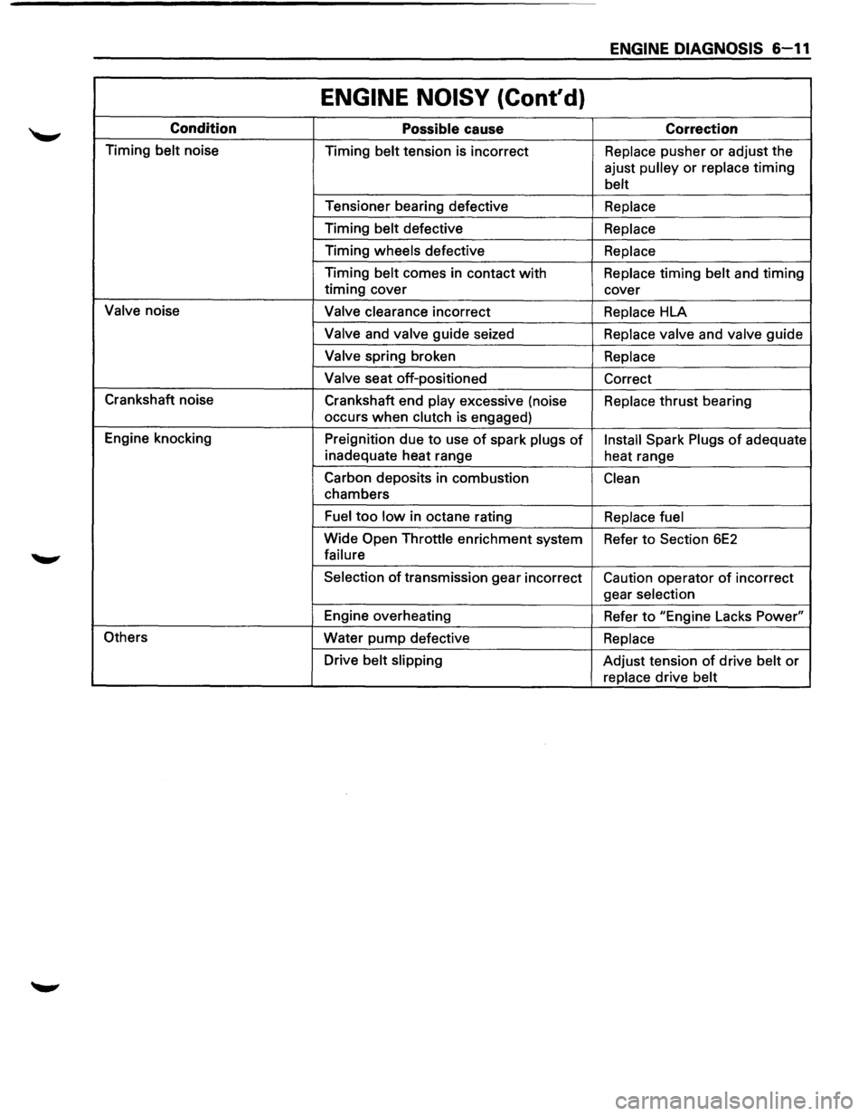
ENGINE DIAGNOSIS 6-11
ENGINE NOISY (Cont'd)
Condition Possible cause Correction
Timing belt noise
Timing belt tension is incorrect Replace pusher or adjust the
ajust
pulley or replace timing
belt
Tensioner bearing defective Replace
Timing belt defective Replace
Timing wheels defective Replace
Timing belt comes in contact with Replace timing belt and timing
timing cover
cover
Valve noise Valve clearance incorrect Replace HLA
Valve and valve guide seized Replace valve and valve guide
Valve spring broken Replace
Valve
seat off-positioned
Correct
Crankshaft noise
Crankshaft end
play excessive (noise Replace thrust bearing
occurs
when clutch is engaged)
Engine knocking
Preignition due
to use of spark plugs of Install Spark Plugs of adequate
inadequate heat range
heat range
Carbon deposits in combustion
Clean
chambers
Fuel too low in octane rating Replace fuel
Wide Open Throttle enrichment system
Refer to Section 6E2
failure
Selection
of transmission gear incorrect Caution operator of incorrect
gear
selection
Engine overheating
Refer to "Engine Lacks Power"
Others Water
pump defective Replace
Drive belt slipping Adjust tension of drive belt or
replace drive belt
Page 510 of 1928
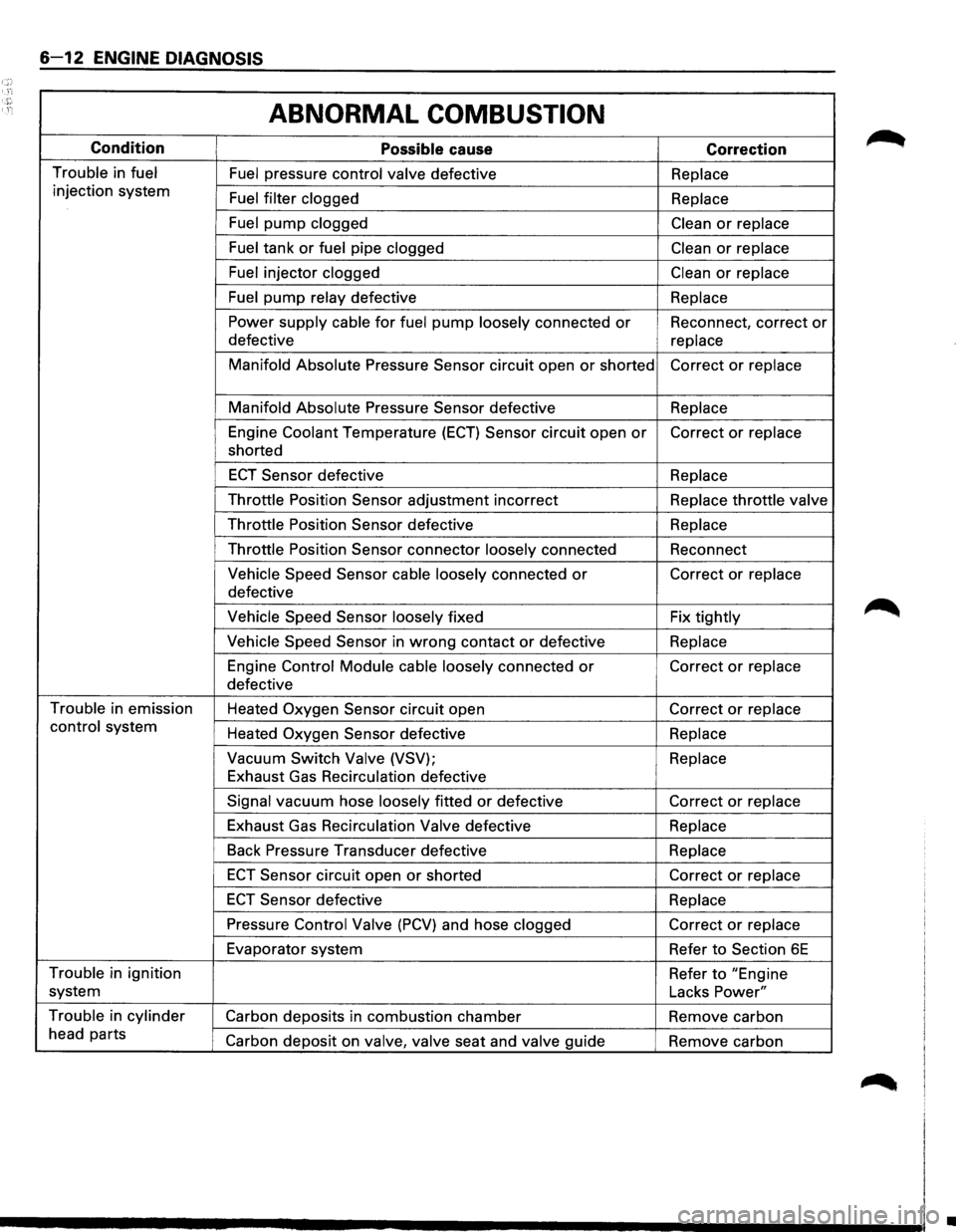
6-12 ENGINE DIAGNOSIS
ABNORMAL COMBUSTION
Condition
Possible cause Correction
Trouble in fuel Fuel pressure control valve defective Replace
injection system
Fuel filter clogged
Replace
Fuel pump clogged Clean or replace
Fuel tank
or fuel pipe clogged Clean or replace
Fuel injector clogged Clean or replace
Fuel
pump relay defective
Replace
Power supply cable for fuel pump loosely connected or Reconnect, correct or
defective
replace
Manifold Absolute
Pressure Sensor circuit open or shorted Correct or replace
Manifold Absolute
Pressure Sensor defective Replace
Engine Coolant Temperature
(ECT) Sensor circuit open or Correct or replace
shorted
ECT Sensor defective
Replace
Throttle
Position Sensor adjustment incorrect Replace throttle valve
Throttle
Position Sensor defective
Replace
Throttle
Position Sensor connector loosely connected Reconnect
Vehicle Speed Sensor cable loosely connected or Correct or replace
defective
Vehicle Speed Sensor loosely fixed Fix tightly
Vehicle Speed Sensor in wrong contact or defective Replace
Engine Control Module cable
loosely connected or Correct or replace
defective
Trouble in emission
Heated
Oxygen Sensor circuit open Correct or replace
control system
Heated
Oxygen Sensor defective Replace
Vacuum Switch
Valve (VSV); Replace
Exhaust Gas Recirculation defective
Signal vacuum hose loosely fitted or defective Correct or replace
Exhaust Gas Recirculation
Valve defective Replace
Back
Pressure Transducer defective Replace
ECT Sensor circuit open or shorted Correct or replace
ECT Sensor defective Replace
Pressure Control Valve (PCV) and hose clogged Correct or replace
Evaporator system
Refer
to Section 6E
Trouble in ignition
Refer to "Engine
system Lacks
Power"
Trouble in cylinder
Carbon deposits in combustion chamber Remove carbon
head parts
Carbon deposit on valve,
valve seat and valve guide
Remove carbon
•
Page 512 of 1928
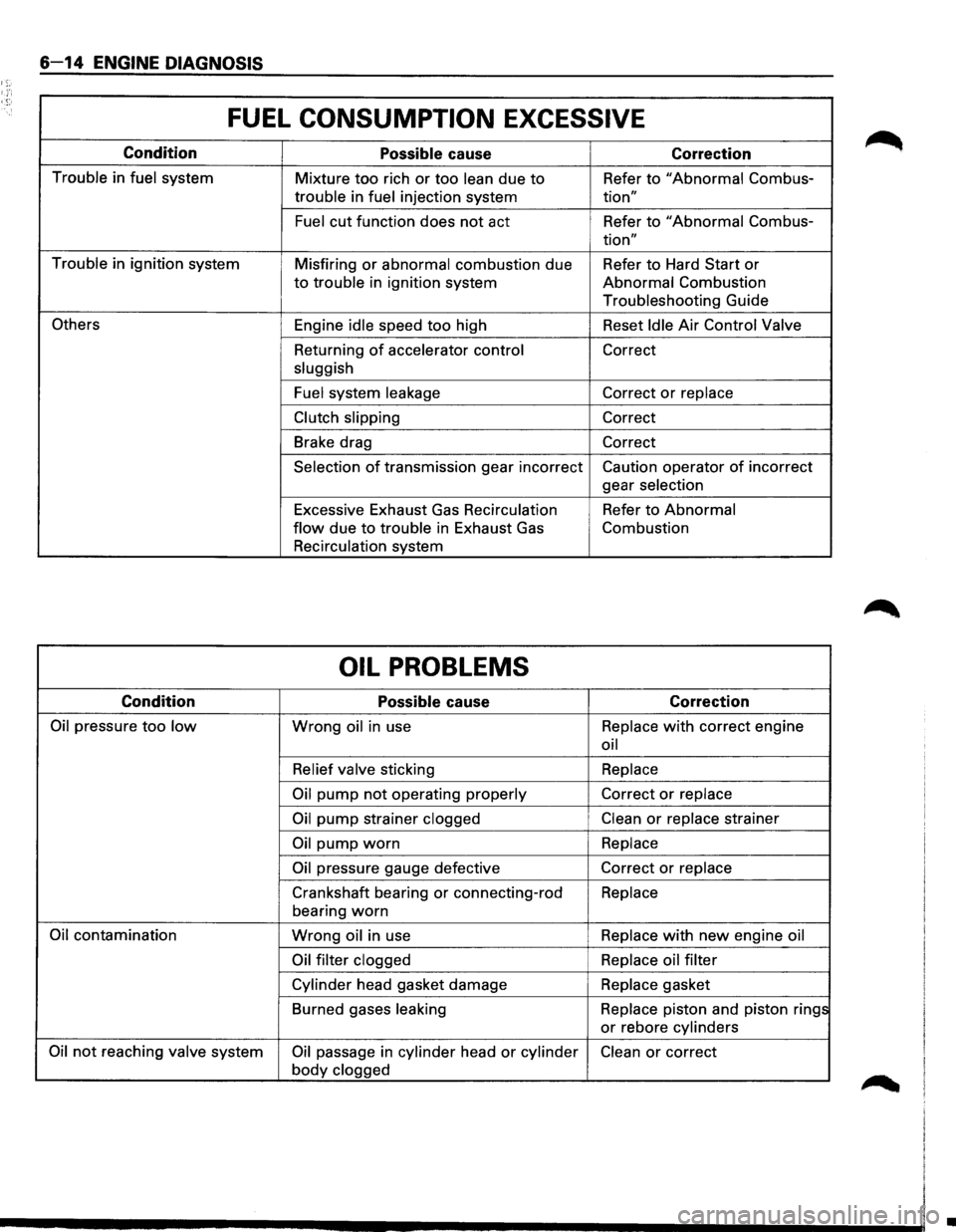
6-14 ENGINE DIAGNOSIS
1;:-
FUEL CONSUMPTION EXCESSIVE
Condition
Possible cause Correction
Trouble in fuel system
Mixture too rich or too lean due to Refer to "Abnormal Combus-
trouble in fuel injection system tion"
Fuel cut function does not act Refer to "Abnormal Combus-
tion"
Trouble in ignition system
Misfiring or abnormal combustion due Refer to Hard Start or
to trouble in ignition system Abnormal Combustion
Troubleshooting Guide
Others Engine idle speed too high Reset Idle Air Control Valve
Returning
of accelerator control Correct
sluggish
Fuel system leakage
Correct or replace
Clutch slipping Correct
Brake drag Correct
Selection of transmission gear incorrect Caution operator of incorrect
gear selection
Excessive Exhaust
Gas Recirculation Refer to Abnormal
flow due to trouble in Exhaust Gas Combustion
Recirculation system
OIL PROBLEMS
Condition
Possible cause Correction
Oil pressure too low Wrong oil in use Replace with correct
engine
oil
Relief valve sticking Replace
Oil pump not operating
properly Correct or replace
Oil pump strainer clogged Clean or replace strainer
Oil pump worn Replace
Oil pressure gauge defective Correct or replace
Crankshaft bearing or connecting-rod Replace
bearing
worn
Oil contamination Wrong oil in use Replace with new engine
oil
Oil filter clogged Replace oil filter
Cylinder head gasket damage Replace
gasket
Burned gases leaking Replace piston and piston rings
or rebore cylinders
Oil not reaching valve system Oil passage in cylinder head or cylinder Clean or correct
body clogged
•
Page 562 of 1928
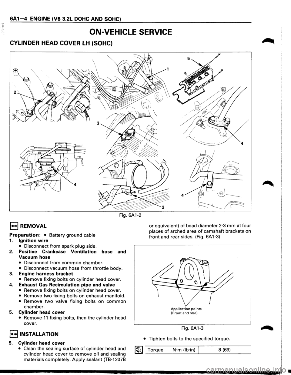
6A1-4 ENGINE (V6 3.2L DOHC AND SOHC)
ON-VEHICLE SERVICE
CYLINDER HEAD COVER LH (SOHC)
1••1 REMOVAL
Preparation: • Battery ground cable
1. Ignition wire
• Disconnect from spark plug side.
2. Positive Crankcase Ventilation hose and
Vacuum hose
• Disconnect from common chamber.
• Disconnect vacuum hose from throttle body.
3. Engine harness bracket
• Remove fixing bolts on cylinder head cover.
4. Exhaust Gas Recirculation pipe and valve
• Remove fixing bolts on cylinder head cover.
• Remove two fixing bolts on exhaust manifold.
•
Remove two valve fixing bolts on common
chamber.
5. Cylinder head cover
• Remove 11 fixing bolts, then the cylinder head
cover.
I••IINST ALLA TION
5. Cylinder head cover
• Clean the sealing surface of cylinder head and
cylinder head cover to remove oil and sealing
materials completely.
Apply sealant (TB-12078
/
~
!8;
4
or equivalent) of bead diameter 2-3 mm at four
places of arched area of camshaft brackets on
front and rear sides. (Fig. 6A 1-3)
Application points (Front and rear)
Fig. 6A1-3
• Tighten bolts to the specified torque.
1~1 Torque N·m (lb·in) 8 (69)
•
Page 563 of 1928
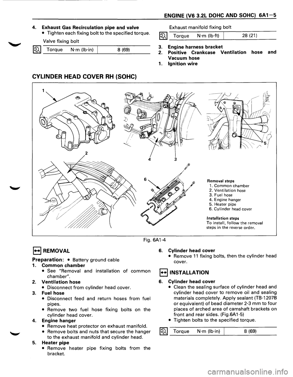
4. Exhaust Gas Recirculation pipe and valve
• Tighten each fixing bolt to the specified torque.
Valve fixing bolt
1«1 Torque N·m (lb·in) 8 (69)
CYLINDER HEAD COVER RH (SOHC)
1
2
4
ENGINE (V6 3.2L DOHC AND SOHC) 6A1-5
Exhaust manifold fixing bolt
1«1 Torque N·m (lb·ft) I 28 (21)
3. Engine harness bracket
2. Positive Crankcase
Ventilation hose and
Vacuum hose
1. Ignition wire
3
Removal steps
1. Common chamber 2. Ventilation hose
3. Fuel hose
4. Engine hanger
5. Heater pipe
6.
Cylinder head cover
Installation steps
To install, follow the removal
steps in the reverse order.
Fig. 6A1-4
EJ REMOVAL
Preparation: • Battery ground cable
1. Common chamber
• See "Removal and installation of common
chamber".
2. Ventilation hose
• Disconnect from cylinder head cover.
3. Fuel hose
• Disconnect feed and return hoses from fuel
pipes.
• Remove two fuel hose fixing bolts on the
cylinder head cover.
4. Engine hanger
• Remove heat protector on exhaust manifold.
•
Remove bolts and nuts that secure the hanger
to the exhaust manifold and cylinder head.
5. Heater pipe
• Remove heater pipe fixing bolts from the
bracket.
6. Cylinder head cover
• Remove 11 fixing bolts, then the cylinder head
cover.
I•+IINSTALLATION
6. Cylinder head cover
• Clean the sealing surface of cylinder head and
cylinder head cover to remove oil and sealing
materials completely.
Apply sealant (TB-12078
or equivalent) of bead diameter 2-3 mm to four
places of arched area of camshaft brackets on
front and rear sides. (Fig.6A 1-5)
• Tighten bolts to the specified torque.
1«1 Torque N·m (lb·in) 8 (69)
Page 566 of 1928
6A1-8 ENGINE (V6 3.2L DOHC AND SOHC)
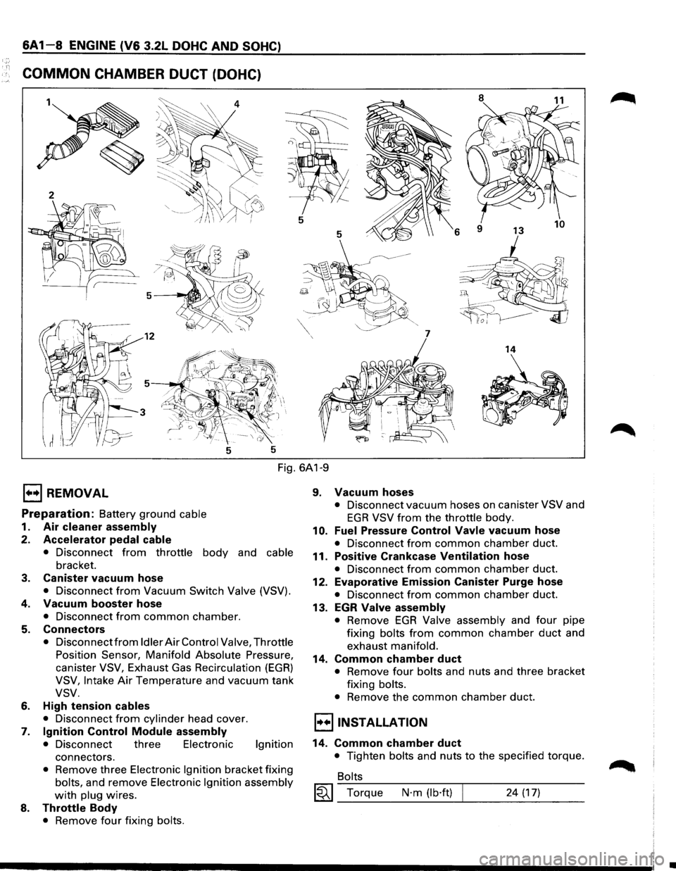
COMMON CHAMBER DUCT (DOHC)
8
11
5
5
6
7
14
5 5
Fig. 6A1-9
E) REMOVAL
Preparation: Battery ground cable
1. Air cleaner assembly
2. Accelerator pedal cable
• Disconnect from throttle body and cable
bracket.
3. Canister vacuum hose
• Disconnect from Vacuum Switch Valve (VSV).
4. Vacuum booster hose
• Disconnect from common chamber.
5. Connectors
• Disconnect from Idler Air Control Valve, Throttle
Position Sensor, Manifold Absolute Pressure,
canister VSV, Exhaust Gas Recirculation (EGR)
VSV, Intake Air Temperature and vacuum tank
vsv.
6. High tension cables
• Disconnect from cylinder head cover.
7. Ignition Control Module assembly
• Disconnect three Electronic Ignition
connectors.
• Remove three Electronic Ignition bracket fixing
bolts, and remove Electronic Ignition assembly
with plug wires.
8. Throttle Body
• Remove four fixing bolts.
9. Vacuum hoses
• Disconnect vacuum hoses on canister VSV and
EGR VSV from the throttle body.
10. Fuel Pressure Control Vavle vacuum hose
• Disconnect from common chamber duct.
11. Positive Crankcase Ventilation hose
• Disconnect from common chamber duct.
12. Evaporative Emission Canister Purge hose
• Disconnect from common chamber duct.
13. EGR Valve assembly
• Remove EGR Valve assembly and four pipe
fixing bolts from common chamber duct and
exhaust manifold.
14. Common chamber duct
• Remove four bolts and nuts and three bracket
fixing bolts.
• Remove the common chamber duct.
l·u·IINSTALLATION
14. Common chamber duct
• Tighten bolts and nuts to the specified torque.
Bolts
~~~ Torque N·m (lb·ft) 24 (17)
•