ignition ISUZU TROOPER 1995 Workshop Manual
[x] Cancel search | Manufacturer: ISUZU, Model Year: 1995, Model line: TROOPER, Model: ISUZU TROOPER 1995Pages: 1928
Page 1737 of 1928
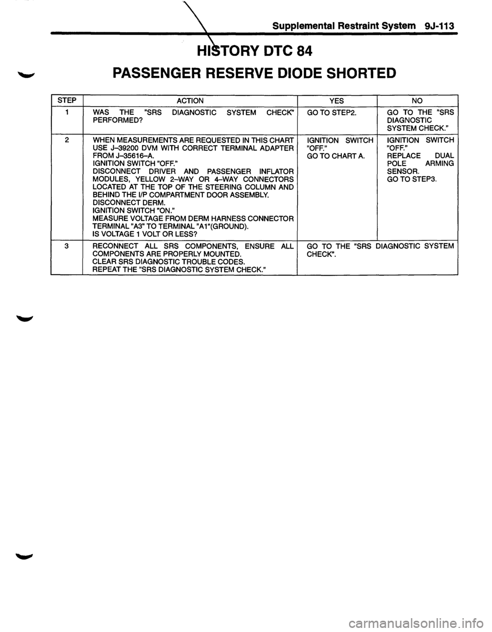
STEP
1
2
3
Supplemental Restraint System 9J-113
HI TORY DTC 84
PASSENGER RESERVE DIODE SHORTED
ACTION
YES NO
WAS
THE "SRS DIAGNOSTIC SYSTEM CHECK'' GOTOSTEP2. GO TO THE "SRS PERFORMED? DIAGNOSTIC
SYSTEM CHECK."
WHEN MEASUREMENTS ARE REQUESTED IN THIS CHART IGNITION SWITCH IGNITION
SWITCH
USE J-39200 DVM WITH CORRECT TERMINAL ADAPTER "OFF." "OFF."
FROM J-35616-A. GO TO CHART A. REPLACE DUAL IGNITION
SWITCH "OFF."
POLE ARMING
DISCONNECT DRIVER
AND PASSENGER INFLATOR SENSOR.
MODULES, YELLOW 2-WAY OR 4-WAY CONNECTORS GOTOSTEP3. LOCATED AT THE TOP OF THE STEERING COLUMN AND BEHIND THE 1/P COMPARTMENT DOOR ASSEMBLY.
DISCONNECT DERM.
IGNITION SWITCH "ON."
MEASURE VOLTAGE FROM DERM HARNESS CONNECTOR
TERMINAL "A3" TO TERMINAL "A1"(GROUND).
IS
VOLTAGE 1 VOLT OR LESS?
RECONNECT ALL SRS COMPONENTS,
ENSURE ALL GO TO THE "SRS DIAGNOSTIC SYSTEM
COMPONENTS ARE PROPERLY MOUNTED.
CHECK".
CLEAR SRS DIAGNOSTIC TROUBLE CODES. REPEAT THE "SRS DIAGNOSTIC SYSTEM CHECK."
Page 1741 of 1928
Supplemental Restraint System 9J-117
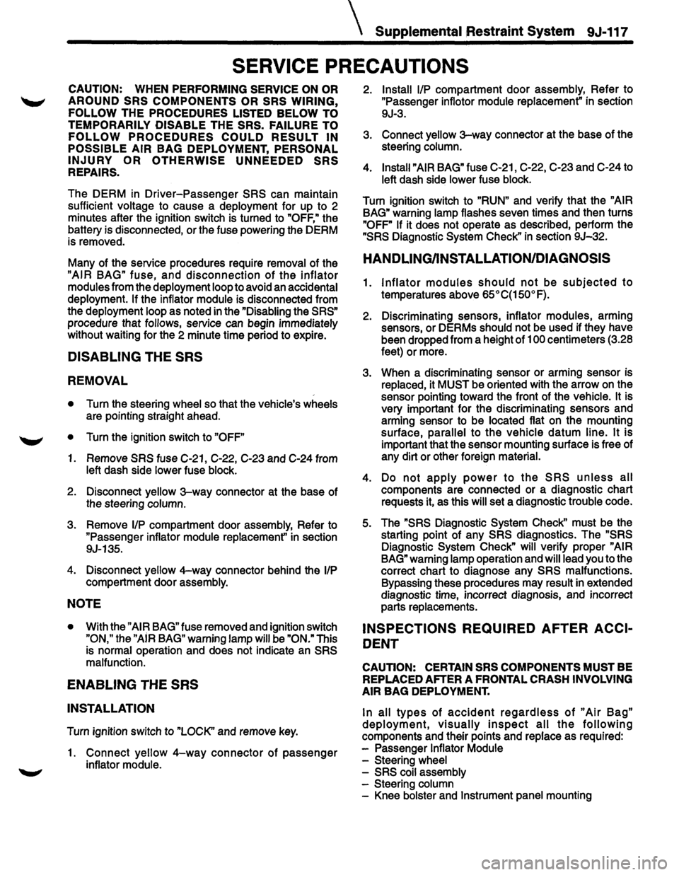
SERVICE PRECAUTIONS
CAUTION: WHEN PERFORMING SERVICE ON OR
AROUND SRS COMPONENTS OR SRS WIRING,
FOLLOW
THE PROCEDURES LISTED BELOW TO
TEMPORARILY
DISABLE THE SRS. FAILURE TO
FOLLOW PROCEDURES COULD RESULT IN
POSSIBLE AIR BAG DEPLOYMENT, PERSONAL
INJURY OR OTHERWISE UNNEEDED SRS
REPAIRS.
The DERM in Driver-Passenger SRS can maintain
sufficient voltage to cause a deployment for up to 2
minutes after the ignition switch is turned to
"OFF," the
battery is disconnected, or the fuse powering the DERM
is removed.
Many of the service procedures require removal of the
"AIR BAG" fuse, and disconnection of the inflator
modules from the deployment loop to avoid an accidental
deployment.
If the inflator module is disconnected from
the deployment loop as noted in the "Disabling the
SRS"
procedure that follows, service can begin immediately
without waiting for the 2 minute time period to expire.
DISABLING THE SRS
REMOVAL
• Turn the steering wheel so that the vehicle's wheels
are pointing straight ahead.
• Turn the ignition switch to "OFF"
1. Remove SRS fuse C-21, C-22, C-23 and C-24 from
left dash side lower fuse block.
2. Disconnect yellow
3-way connector at the base of
the steering column.
3. Remove
liP compartment door assembly, Refer to
"Passenger inflator module replacemenf' in section
9J-135.
4. Disconnect yellow 4-way connector behind the liP
compartment door assembly.
NOTE
• With the" AIR BAG" fuse removed and ignition switch
"ON," the "AiR BAG" warning lamp will be "ON." This
is normal operation and does not indicate
an SRS
malfunction.
ENABLING THE SRS
INSTALLATION
Turn ignition switch to "LOCK" and remove key.
1. Connect yellow 4-way connector of passenger
inflator module.
2. Install liP compartment door assembly, Refer to
"Passenger inflator module replacement" in section
9J-3.
3. Connect yellow 3-way connector at the base of the
steering column.
4. Install" AIR BAG" fuse C-21, C-22, C-23 and C-24 to
left dash side lower fuse block.
Tum ignition switch to
"RUN" and verify that the "AIR
BAG"
warning lamp flashes seven times and then turns
"OFF" If it does not operate as described, perform the
"SRS Diagnostic System Check" in section 9J-32.
HANDLING/INSTALLATION/DIAGNOSIS
1. Inflator modules should not be subjected to
temperatures above 65°C(150°F).
2. Discriminating s~nsors, inflator modules, arming
sensors, or DERMs should not be used if they have
been dropped from a height of 1
00 centimeters (3.28
feet) or more.
3. When a discriminating sensor or arming sensor is
replaced, it MUST be oriented with the arrow
on the
sensor pointing toward the front of the vehicle.
It is
very important for the discriminating sensors and
arming sensor to be located flat on the mounting
surface, parallel to the vehicle datum line.
It is
important that the sensor mounting surface is free of
any dirt or other foreign material.
4. Do not apply power to the SRS unless all
components are connected or a diagnostic chart
requests it, as this
will set a diagnostic trouble code.
5. The
"SRS Diagnostic System Check'' must be the
starting point of any SRS diagnostics. The
"SRS
Diagnostic System Check" will verify proper "AIR
BAG" warning lamp operation and will lead you to the
correct chart to diagnose any SRS malfunctions.
Bypassing these procedures may result in extended
diagnostic time, incorrect diagnosis, and incorrect
parts replacements.
INSPECTIONS REQUIRED AFTER ACCI
DENT
CAUTION: CERTAIN SRS COMPONENTS MUST BE
REPLACED AFTER A FRONTAL
CRASH INVOLVING
AIR
BAG DEPLOYMENT.
In all types of accident regardless of "Air Bag"
deployment, visually inspect all the following
components and their points and replace as required:
- Passenger
Inflator Module
- Steering wheel
- SRS coil assembly
- Steering column
- Knee bolster and
Instrument panel mounting
Page 1893 of 1928
BODY 1Q-135
KEY
KEY CODING
KEY USAGE AND IDENTIFICATION
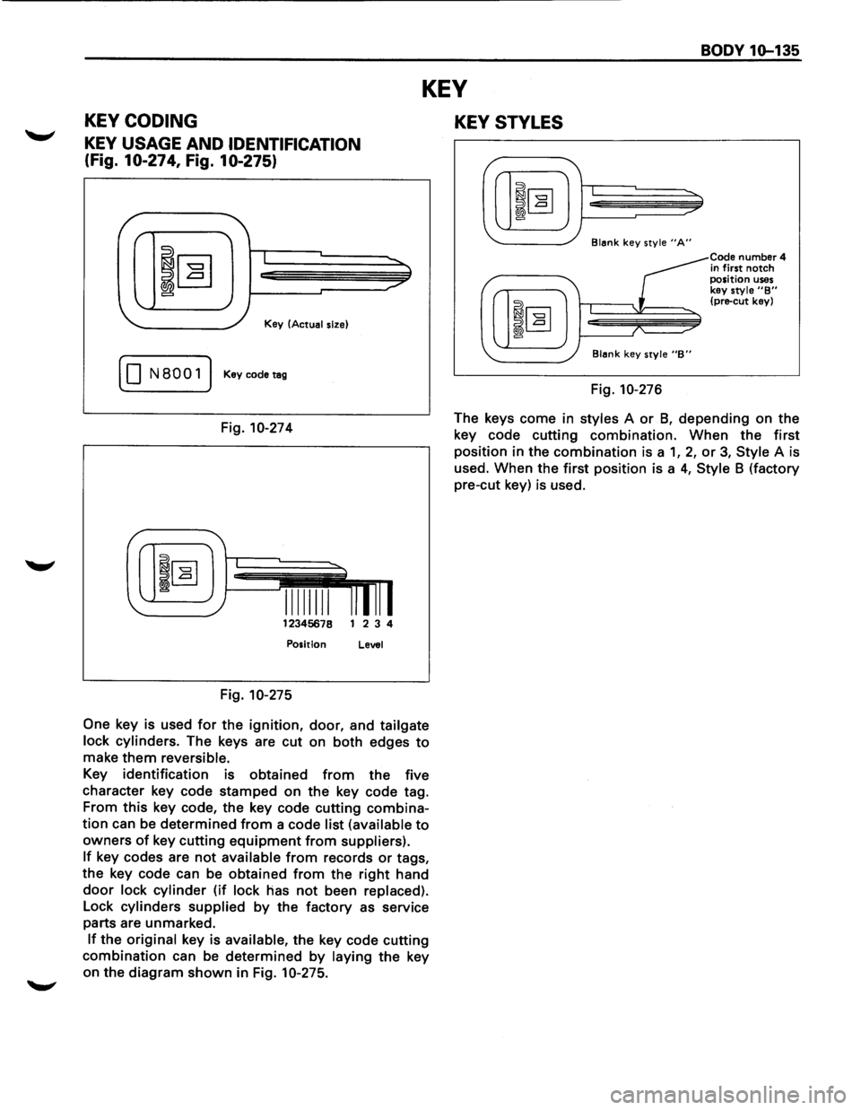
(Fig. 10-274, Fig. 10-275)
I
Key (Actual size)
( 0 N8001) Keycodetag
Fig. 10-274
12345678 1 2 3 4
Position Level
Fig. 10-275
One
key is used for the ignition, door, and tailgate
lock cylinders.
The keys are cut on both edges to
make them reversible.
Key identification is obtained from the five
character key code stamped on
the key code tag.
From
this key code, the key code cutting combina
tion can be determined from a code list (available to
owners of key cutting equipment from suppliers).
If key codes are not available from records or tags,
the key code can be obtained
from the right hand
door lock cylinder (if lock has not been replaced).
Lock cylinders supplied by the factory as service
parts are unmarked.
If the original key is available, the key code cutting
combination can be determined by laying the key
on the diagram
shown in Fig. 10-275.
KEY STYLES
Blank key style "A"
Blank key style "B"
Fig. 10-276
Code number 4
in first notch position uses key style "B" (pre-cut key)
The keys come in styles A or 8, depending on the
key code cutting combination. When the
first
position in the combination is a 1, 2, or 3, Style A is
used. When the
first position is a 4, Style 8 (factory
pre-cut key) is used.