ignition ISUZU TROOPER 1995 Workshop Manual
[x] Cancel search | Manufacturer: ISUZU, Model Year: 1995, Model line: TROOPER, Model: ISUZU TROOPER 1995Pages: 1928
Page 732 of 1928
6E2-36 DRIVEABILITV AND EMISSIONS
ON-BOARD DIAGNOSTIC (OBD) SYSTEM CHECK
The on-board diagnostic system check is an organized approach to identifying a problem created by an Electronic
Engine
Control System malfunction. It must be the starting point for any driveability complaint diagnosis, because
it directs the service technician to the next logical step in diagnosing the complaint. Understanding the chart and
using
it correclty will reduce diagnostic time and prevent the unnecessary replacement of good parts.
Test Description:
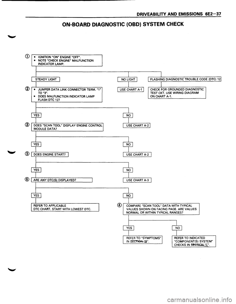
Number(s) below refer to circled number(s) on the following diagnostic chart.
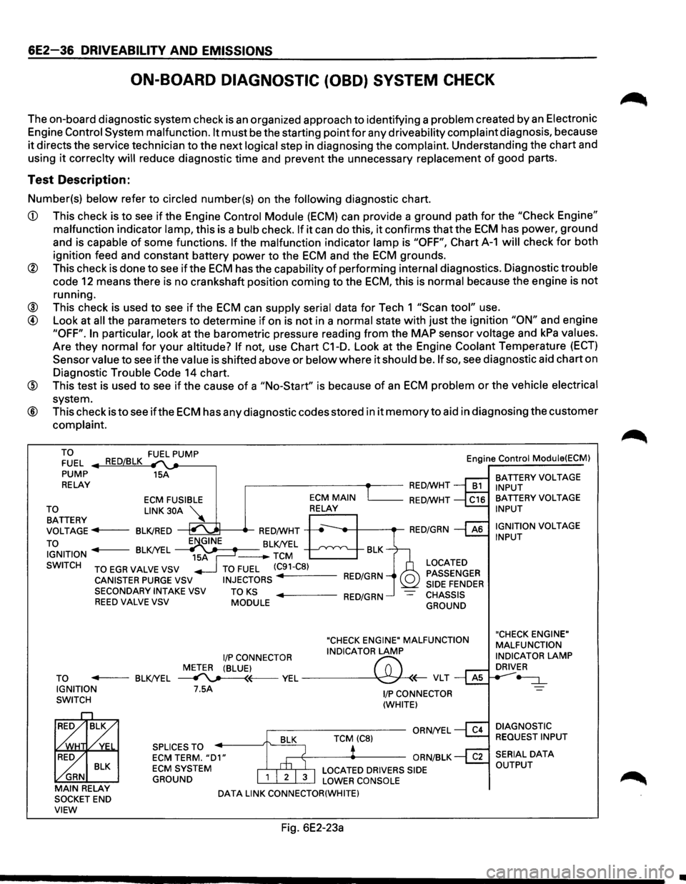
CD This check is to see if the Engine Control Module (ECM) can provide a ground path for the "Check Engine"
malfunction indicator lamp, this is a bulb check. If it can do this, it confirms that the ECM has power, ground
and is capable
of some functions. If the malfunction indicator lamp is "OFF", Chart A-1 will check for both
ignition feed and constant battery power to the
ECM and the ECM grounds.
® This check is done to see if the ECM has the capability of performing internal diagnostics. Diagnostic trouble
code
12 means there is no crankshaft position coming to the ECM, this is normal because the engine is not
running.
® This check is used to see if the ECM can supply serial data for Tech 1 "Scan tool" use.
@ Look at all the parameters to determine if on is not in a normal state with just the ignition "ON" and engine
"OFF". In particular, look at the barometric pressure reading from the MAP sensor voltage and kPa values.
Are they normal for
your altitude? If not, use Chart C1-D. Look at the Engine Coolant Temperature (ECT)
Sensor value to see if the value is shifted above or below where it should be. If so, see diagnostic aid chart on
Diagnostic Trouble
Code 14 chart.
@ This test is used to see if the cause of a "No-Start" is because of an ECM problem or the vehicle electrical
system.
® This check is to see ifthe ECM has any diagnostic codes stored in it memory to aid in diagnosing the customer
complaint.
TO FUEL
PUMP
RELAY 15A
,------------+--RED/WHT Engine
Control Module(ECM)
BATTERY
VOLTAGE INPUT
ECM FUSIBLE L_ __ RED/WHT
~~TTERY LINK 30A ~
VOLTAGE ..,.,.f----BLK/RED
TO
~t-----tr-RED/WHT -----,t--+---.-RED/GRN
IGNITION BLK/YEL J-------BLK/YEL -TCM BLK
SWITCH
TO EGR VALVE VSV
CANISTER PURGE VSV SECONDARYINTAKEVSV REED VALVE VSV
TO FUEL (C91-C8)
INJECTORS RED/GRN
TO KS MODULE ..,._ ___ RED/GRN
LOCATED
PASSENGER
SIDE
FENDER CHASSIS
GROUND
"CHECK ENGINE" MALFUNCTION
I/P CONNECTOR INDICATOR LAMP
METER (BLUE)
f'7:' TO ..,._ __ BLK/YEL ~~VEL~(;-VLT IGNITION
SWITCH 7.5A
SPLICES TO
ECM TERM. "D1" ECM SYSTEM
GROUND
DATA LINK CONNECTOR(WHITE)
Fig. 6E2-23a
1/P CONNECTOR
(WHITE)
BATTERY VOLTAGE INPUT
IGNITION
VOLTAGE INPUT
"CHECK ENGINE"
MALFUNCTION
INDICATOR
LAMP DRIVER
-=:J._
DIAGNOSTIC
REQUEST INPUT
•
Page 733 of 1928
DRIVEABILITY AND EMISSIONS 6E2-37
ON-BOARD DIAGNOSTIC (OBD) SYSTEM CHECK
(j) • IGNITION "ON" ENGINE "OFF".
• NOTE "CHECK ENGINE" MALFUNCTION INDICATOR LAMP.
STEADY LIGHT
@ • JUMPER DATA LINK CONNECTOR TERM. "1" TO "3".
• DOES MALFUNCTION INDICATOR LAMP FLASH DTC 127
@ DOES "SCAN TOOL" DISPLAY ENGINE CONTROL MODULE DATA?
REFER TO APPLICABLE DTC CHART. START WITH LOWEST DTC.
CHECK FOR GROUNDED DIAGNOSTIC TEST CKT. USE WIRING DIAGRAM ON CHART A-1.
@ COMPARE "SCAN TOOL" DATA WITH TYPICAL VALUES SHOWN ON FACING PAGE. ARE VALUES NORMAL OR WITHIN TYPICAL RANGES?
REFER TO INDICATED "COMPONENT(S) SYSTEM" CHECKS IN~·.
Page 734 of 1928
6E2-38 DRIVEABILITV AND EMISSIONS
CHART A-1
WILL NOT FLASH DIAGNOSTIC TROUBLE CODE (DTC) 12
NO "CHECK ENGINE" MALFUNCTION INDICATOR LAMP (MIL)
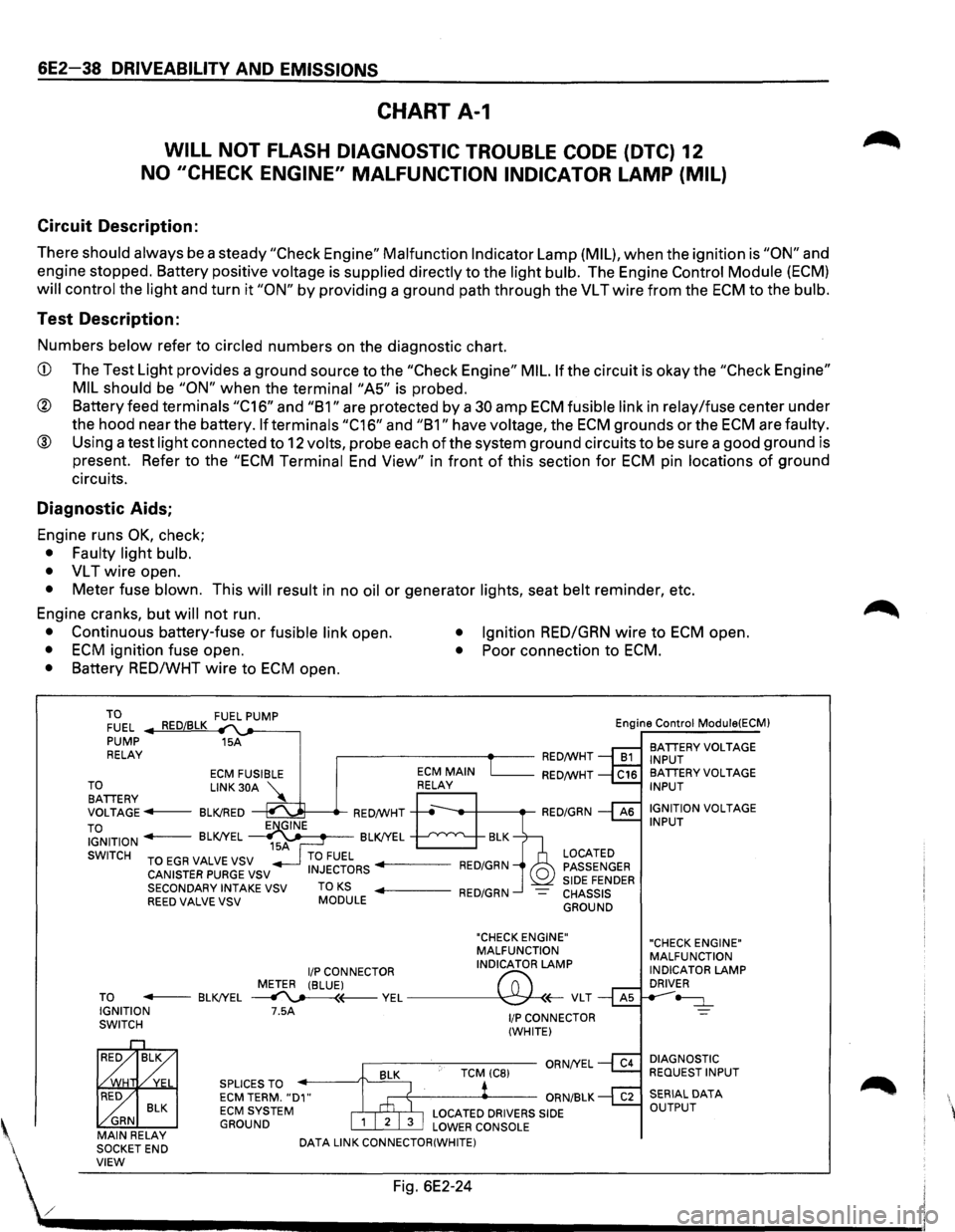
Circuit Description:
There should always be a steady "Check Engine" Malfunction Indicator Lamp (MIL), when the ignition is "ON" and
engine stopped. Battery positive
voltage is supplied directly to the light bulb. The Engine Control Module (ECM)
will control the light and turn it "ON" by providing a ground path through the VL T wire from the ECM to the bulb.
Test Description:
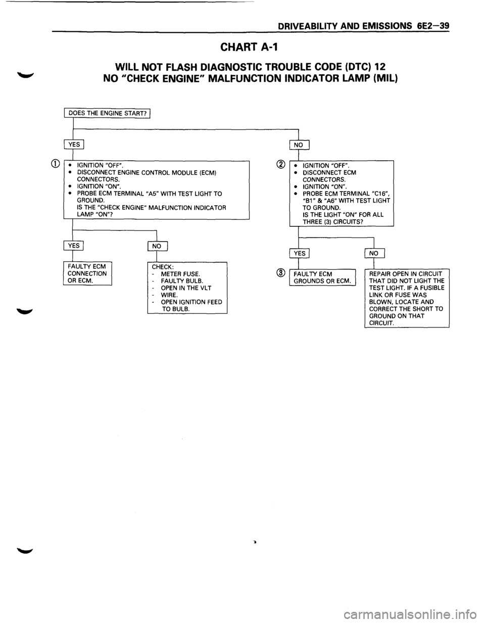
Numbers below refer to circled numbers on the diagnostic chart.
CD The Test Light provides a ground source to the "Check Engine" MIL. If the circuit is okay the "Check Engine"
MIL should
be "ON" when the terminai"A5" is probed.
® Battery feed terminals "C16" and "B1" are protected by a 30 amp ECM fusible link in relay/fuse center under
the hood near the battery.
If terminals "C16" and "B1" have voltage, the ECM grounds or the ECM are faulty.
® Using a test light connected to 12 volts, probe each of the system ground circuits to be sure a good ground is
present. Refer to the
"ECM Terminal End View" in front of this section for ECM pin locations of ground
circuits.
Diagnostic Aids;
Engine runs OK, check;
• Faulty light bulb.
•
VL T wire open.
• Meter fuse blown. This will result in no oil or generator lights, seat belt reminder, etc.
Engine cranks, but
will not run.
• Continuous battery-fuse or fusible link open. • Ignition RED/GRN wire to ECM open.
• ECM ignition fuse open. • Poor connection to ECM.
• Battery RED/WHT wire to ECM open.
TO FUEL .._..,==~ ,__,__-----, PUMP 15A
RELAY .--------~~-RED/WHT Engine
Control
Module(ECM)
BATIERY VOLTAGE
INPUT
ECM FUSIBLE RED/WHT TO LINK 30A '\.. BATIERY ~ VOLTAGE---BLK!RED ~---.-RED/WHT
TO IGNITION - BLK!YEL ~~~-BLK!YEL --'--'~"'---..__
SWITCH TO EGR VALVE VSV
CANISTER PURGE VSV
SECONDARY INTAKE VSV
REED VALVE VSV TO KS MODULE
LOCATED
PASSENGER
SIDE FENDER CHASSIS GROUND
"CHECK ENGINE"
MALFUNCTION
I/P CONNECTOR INDICATOR LAMP
METER (BLUE)
("";:; TO - BLK!YEL ~(---VEL~(;-VLT IGNITION 7.5A SWITCH
BLK ~ GRN MAIN RELAY
SOCKETEND SPLICES
TO ECM TERM. "D1" ECM SYSTEM GROUND
DATA
LINK CONNECTOR(WHITE)
1/P CONNECTOR
(WHITE)
BA TIERY VOLTAGE INPUT
IGNITION
VOLTAGE INPUT
"CHECK ENGINE"
MALFUNCTION
INDICATOR
LAMP DRIVER
~
DIAGNOSTIC REQUEST INPUT
' VIEW Fig. 6E2-24
./ .................................... __________________________ _
Page 735 of 1928
DRIVEABILITV AND EMISSIONS 6E2-39
CHART A-1
WILL NOT FLASH DIAGNOSTIC TROUBLE CODE (DTC) 12
NO 11CHECK ENGINE" MALFUNCTION INDICATOR LAMP (MIL)
CD • IGNITION "OFF".
• DISCONNECT ENGINE CONTROL MODULE (ECM) CONNECTORS.
• IGNITION "ON". • PROBE ECM TERMINAL "A5" WITH TEST LIGHT TO GROUND. IS THE "CHECK ENGINE" MALFUNCTION INDICATOR LAMP "ON"?
FAULTY ECM CONNECTION OR ECM. CHECK:
- METER FUSE. FAUL TV BULB. OPEN IN THE VL T
-WIRE. -OPEN IGNITION FEED TO BULB.
@ • IGNITION "OFF".
®
• DISCONNECT ECM CONNECTORS.
• IGNITION "ON".
• PROBE
ECM TERMINAL "C16", "B1" & "A6" WITH TEST LIGHT
TO GROUND. IS THE LIGHT "ON" FOR ALL THREE (3) CIRCUITS?
REPAIR OPEN IN CIRCUIT
THAT DID NOT LIGHT THE TEST LIGHT. IF A FUSIBLE
LINK OR FUSE WAS BLOWN, LOCATE AND CORRECT THE SHORT TO
GROUND ON THAT CIRCUIT.
Page 736 of 1928
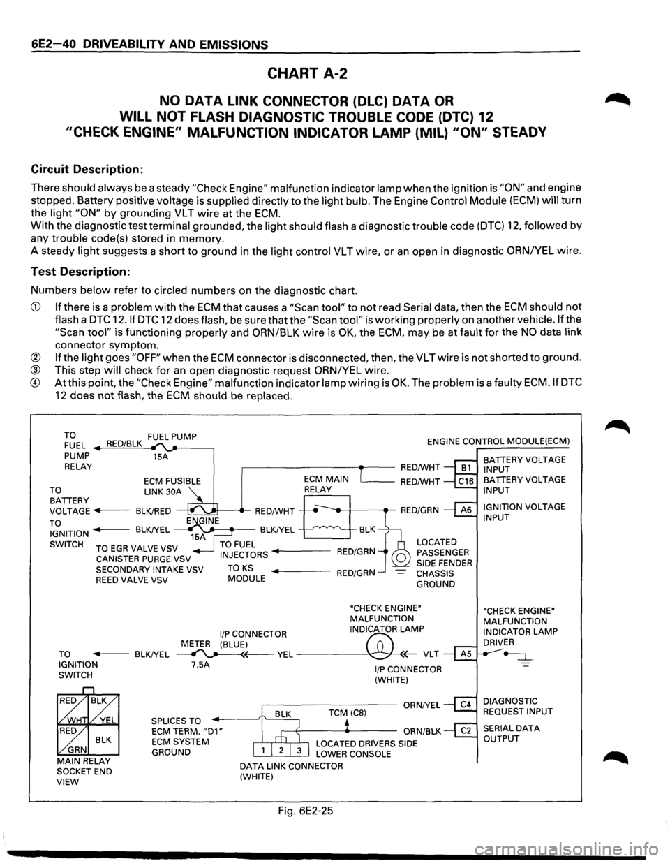
6E2-40 DRIVEABILITY AND EMISSIONS
CHART A-2
NO DATA LINK CONNECTOR (DLC) DATA OR
WILL NOT FLASH DIAGNOSTIC TROUBLE CODE (DTC) 12
"CHECK ENGINE" MALFUNCTION INDICATOR LAMP (MIL) "ON" STEADY
Circuit Description:
There should always be a steady "Check Engine" malfunction indicator lamp when the ignition is "ON" and engine
stopped. Battery positive
voltage is supplied directly to the light bulb. The Engine Control Module (ECM) will turn
the
light "ON" by grounding VLT wire at the ECM.
With the diagnostic test terminal grounded, the light should flash a diagnostic trouble code (DTC) 12, followed by
any trouble code(s) stored in memory.
A steady
light suggests a short to ground in the light control VLT wire, or an open in diagnostic ORNIYEL wire.
Test Description:
Numbers below refer to circled numbers on the diagnostic chart.
CD If there is a problem with the ECM that causes a "Scan tool" to not read Serial data, then the ECM should not
flash a DTC 12.1f DTC 12 does flash, be sure that the "Scan tool" is working properly on anothervehicle.lfthe
"Scan tool" is functioning properly and ORN/BLK wire is OK, the ECM, may be at fault for the NO data link
connector symptom.
@ If the light goes "OFF" when the ECM connector is disconnected, then, the VLTwire is not shorted to ground.
® This step will check for an open diagnostic request ORN/YEL wire.
® At this point, the "Check Engine" malfunction indicator lamp wiring is OK. The problem is a faulty ECM.IfDTC
12 does not flash, the ECM should be replaced.
TO FUEL PUMP
FUEL RED/BLK ENGINE CONTROL MODULE(ECM)
PUMP 15A
RELAY
,.-------------.--RED/WHT
TO BATTERY
ECM FUSIBLE
LINK 30A
VOLTAGE
...,. .. 1---BLK!RED
TO IGNITION
SWITCH ENGINE
15A
'------RED/WHT
BLK
BLK!YEL
~ BLK!YEL
TO EGA VALVE VSV TO FUEL CANISTER PURGE VSV INJECTORS ..._ ___ RED/GRN
LOCATED
PASSENGER
SIDE
FENDER CHASSIS
GROUND
SECONDARY
INTAKE VSV TO KS ..._ ___ RED/GRN REED VALVE VSV MODULE
"CHECK ENGINE"
MALFUNCTION
liP CONNECTOR INDICATOR
LAMP
METER (BLUE)
f'7:'
TO -----BLK!YEL ~~ YEL ---\C:;J-
BLK
GRN
MAIN RELAY SOCKET END VIEW
7.5A
SPLICES TO ECM TERM. "D1" ECM SYSTEM
GROUND
DATA LINK CONNECTOR
(WHITE)
Fig. 6E2-25
I/P CONNECTOR
(WHITE)
BATTERY VOLTAGE
INPUT
BATTERY VOLTAGE
INPUT
IGNITION
VOLTAGE INPUT
"CHECK ENGINE"
MALFUNCTION
INDICATOR
LAMP DRIVER
~
DIAGNOSTIC
REQUEST INPUT
Page 737 of 1928
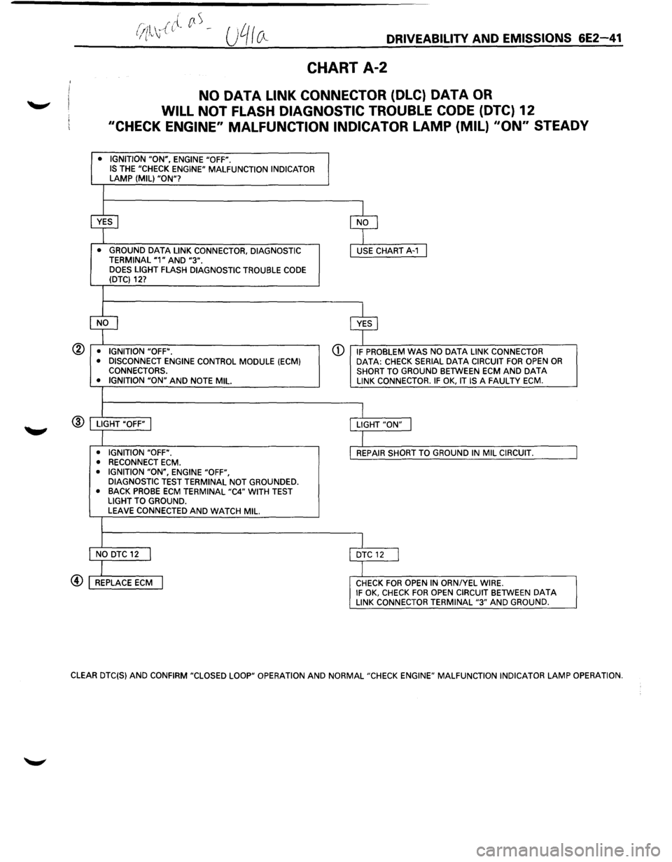
®
.... /"{ rtS (ill .. , (. --f (.'' \J DRIVEABILITV AND EMISSIONS 6E2-41
CHART A-2
NO DATA LINK CONNECTOR (DLC) DATA OR
WILL NOT FLASH DIAGNOSTIC TROUBLE CODE (DTC) 12
"CHECK ENGINE" MALFUNCTION INDICATOR LAMP (MIL) "ON" STEADY
• IGNITION "ON", ENGINE "OFF". IS THE "CHECK ENGINE" MALFUNCTION INDICATOR LAMP (MIL) "ON"?
~ $
• GROUND DATA LINK CONNECTOR, DIAGNOSTIC USE CHART A-1 I TERMINAL "1" AND "3". DOES LIGHT FLASH DIAGNOSTIC TROUBLE CODE (DTC) 12?
$ $
• IGNITION "OFF". G) IF PROBLEM WAS NO DATA LINK CONNECTOR
• DISCONNECT ENGINE CONTROL MODULE (ECM) DATA: CHECK SERIAL DATA CIRCUIT FOR OPEN OR CONNECTORS.
SHORT TO GROUND BETWEEN ECM AND DATA • IGNITION "ON" AND NOTE MIL LINK CONNECTOR. IF OK, IT IS A FAULTY ECM.
I LIGHT "OFF" I LIGHT "ON" j
I • IGNITION "OFF". REPAIR SHORT TO GROUND IN MIL CIRCUIT.
• RECONNECT ECM.
• IGNITION "ON", ENGINE "OFF",
DIAGNOSTIC TEST TERMINAL NOT GROUNDED.
• BACK
PROBE ECM TERMINAL "C4" WITH TEST
LIGHT TO GROUND.
LEAVE CONNECTED AND WATCH MIL.
I NO DTC 12 I DTC 12 I
I REPLACE ECM I CHECK FOR OPEN IN ORNIYEL WIRE. IF OK, CHECK FOR OPEN CIRCUIT BETWEEN DATA LINK CONNECTOR TERMINAL "3" AND GROUND.
CLEAR DTC(S) AND CONFIRM "CLOSED LOOP" OPERATION AND NORMAL"CHECK ENGINE" MALFUNCTION INDICATOR LAMP OPERATION.
Page 738 of 1928
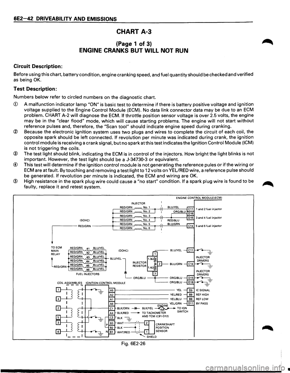
6E2-42 DRIVEABILITV AND EMISSIONS
CHART A-3
(Page 1 of 3)
ENGINE CRANKS BUT WILL NOT RUN
Circuit Description:
Before using this chart, battery condition, engine cranking speed, and fuel quantity should be checked and verified
as being OK.
Test Description:
Numbers below refer to circled numbers on the diagnostic chart.
CD A malfunction indicator lamp "ON" is basic test to determine if there is battery positive voltage and ignition
voltage supplied to the Engine Control Module (ECM). No data link connector data may be due to an ECM
problem. CHART A-2 will diagnose the ECM. If throttle position sensor voltage is over 2.5 volts, the engine
may be in the
"clear flood" mode, which will cause starting problems. The engine will not start without
reference pulses and, therefore, the "Scan tool" should indicate engine speed during cranking.
@ Because the electronic ignition system uses two plugs and wires to complete the circuit of each coil, the
opposite spark
should be left connected. If revolution per minute was indicated during crank, the ignition
control module is receiving a crank signal, but no spark at this test indicates the Ignition Control Module (ICM)
is not triggering the coils.
® The test light should blink, indicating the ECM is in control of the injectors. How bright the light blinks is not
important. However, the test light should be a J-34730-3 or equivalent.
@ This test will determine if the ignition control module is not generating the reference pules or if the wiring or
ECM are at fault. By touching and removing a test light to 12 volts on VEL/RED wire, a reference pulse should
be generated. If revolution per minute is indicated, the ECM and wiring are OK.
® High resistance in the spark plug wire could cause a "no start" condition. If a spark plug wire is found to be
faulty, replace it and retest system.
(SOHC)
I"M"
TOECM RED/GRN #1 BLU/YEL MAIN RED/GRN #2 BLU/YEL
RELAY
tRED/GRN
RED/GRN #3 BLU/YEL
RED/GRN #4 BLU/YEL
RED/GRN
#5 BLU/YEL
RED/GRN
#6 BLU/YEL
FUEL
INJECTORS ENGINE
CONTROL MODULE(ECM)
INJECTOR
RED/GRN
RED/GRN
RED/GRN
RED/GRN
RED/GRN
RED/GRN
IDOHCI BLU/YEL
BLU/YEL
l 1.3!l INJECTOR RESISTOR 1_
ORG/BLU
--+----
E~INE YEL/GRN D11 BLK/ORN -4>-BLK/YEL ----41sv---TO IGN BLK/RED -TOTACHOMETER SWITCH
BLK --:::L =
AND TCM (C91-D12)
CRANKSHAFT
POSITION
1 SENSOR
-........:::SHIELD
Fig. 6E2-26
•
Page 739 of 1928
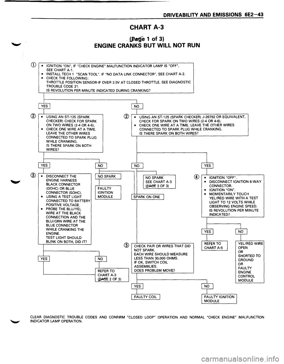
DRIVEABILITY AND EMISSIONS 6E2-43
CHART A-3
-JJ!atfe 1 of 3)
ENGINE CRANKS BUT WILL NOT RUN
Q) • IGNITION "ON", IF "CHECK ENGINE" MALFUNCTION INDICATOR LAMP IS "OFF", SEE CHART A-1. • INSTALL TECH 1 "SCAN TOOL". IF "NO DATA LINK CONNECTOR", SEE CHART A-2. • CHECK THE FOLLOWING: THROTTLE POSITION SENSOR-IF OVER 2.5V AT CLOSED THROTTLE, SEE DIAGNOSTIC
TROUBLE CODE 21. IS REVOLUTION PER MINUTE INDICATED DURING CRANKING?
® • USING AN ST-125 (SPARK CHECKER) CHECK FOR SPARK ON TWO WIRES (2-4 OR 4-6).
® • USING AN ST-125 (SPARK CHECKER) J-26792 OR EQUIVALENT, CHECK FOR SPARK ON TWO WIRES (2-4 OR 4-6).
• CHECK ONE WIRE AT A TIME. LEAVE THE OTHER WIRES CONNECTED TO SPARK PLUG
WHILE CRANKING.
IS THERE SPARK ON BOTH
WIRES?
@ • DISCONNECT THE ENGINE HARNESS BLACK CONNECTOR
(DOHC) OR BLUE CONNECTOR (SOHC).
• USING A TEST LIGHT CONNECTED TO BATTERY POSITIVE VOLTAGE. • PROBE THE BLUIYEL
WIRE AT THE BLACK CONNECTION AND THE
BLU/GRN WIRE AT THE BLUE CONNECTOR
WHILE CRANKING THE ENGINE.
TEST LIGHT SHOULD
BLINK ON BOTH, DID
IT?
FAULTY IGNITION
MODULE
REFER TO L-----------1 CHART A-3
~20F3)
• CHECK ONE WIRE AT A TIME. LEAVE THE OTHER WIRES CONNECTED TO SPARK PLUG WHILE CRANKING. IS THERE SPARK ON BOTH WIRES?
NO SPARK
@ • IGNITION "OFF". SEE CHART A-3 (eA8£3 OF 3)
SPARK ON ONE
@ CHECK PAIR OR WIRES THAT DID
NOT SPARK.
EACH WIRE SHOULD MEASURE
LESS THAN 30,000 OHMS. IF OK, SWITCH COIL
ASSEMBLIES. DOES PROBLEM MOVE? •
DISCONNECT IGNITION
6-WAY CONNECTOR.
• IGNITION "ON". • MOMENTARILY TOUCH VEL/RED WIRE WITH A TEST
LIGHT TO 12 VOLTS WHILE
OBSERVING ENGINE SPEED.
IS REVOLUTION PER MINUTE
INDICATED?
VEL/RED WIRE OPEN OR SHORTED TO
GROUND
OR FAULTY ENGINE
CONTROL MODULE
CLEAR DIAGNOSTIC TROUBLE CODES AND CONFIRM "CLOSED LOOP" OPERATION AND NORMAL "CHECK ENGINE" MALFUNCTION
INDICATOR LAMP OPERATION.
Page 741 of 1928
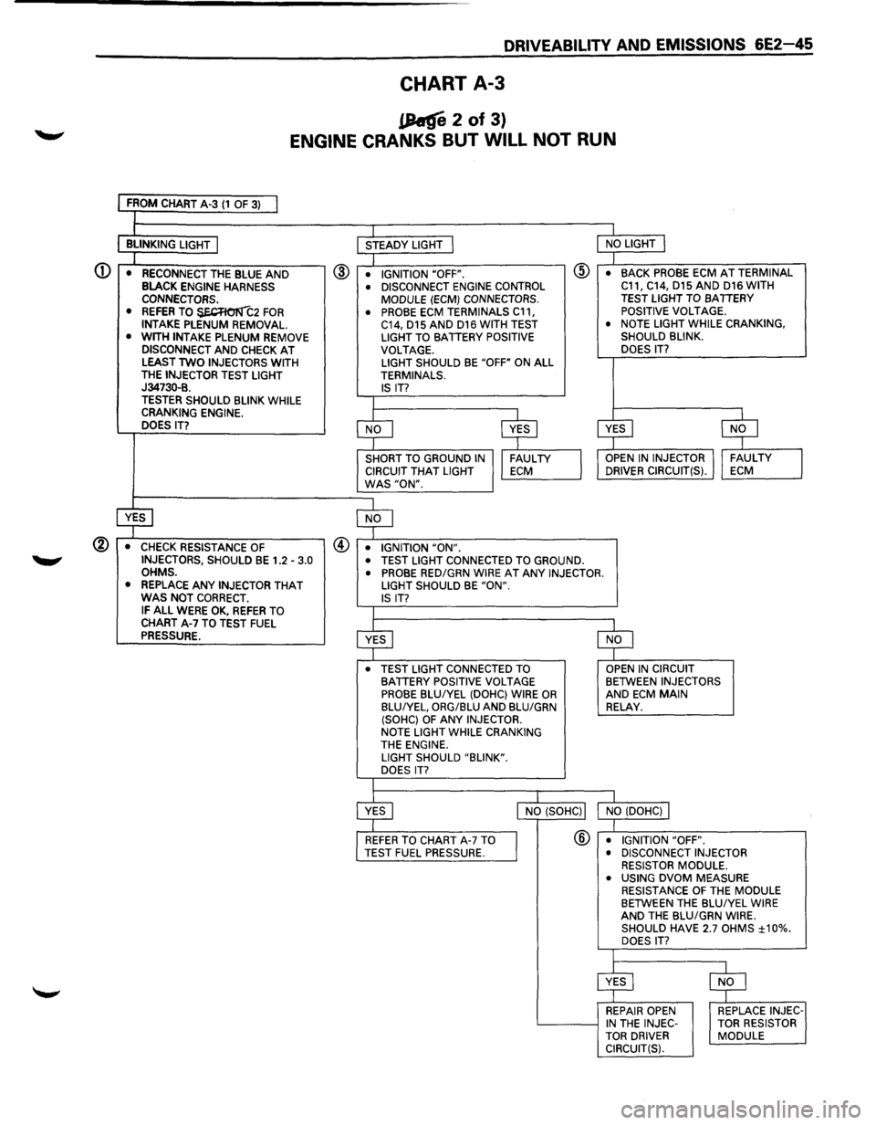
CHART A-3
.(hfi 2 of 3)
ENGINE CRANKS BUT WILL NOT RUN
FROM CHART A-3 (1 OF 3) I l j_ I
BLINKING LIGHT I STEADY LIGHT I NO LIGHT j
I
I @ • RECONNECT THE BLUE AND @ • IGNITION "OFF". •
BACK PROBE ECM AT TERMINAL BLACK ENGINE HARNESS • DISCONNECT ENGINE CONTROL C11,
C14, D15 AND D16 WITH
CONNECTORS. MODULE (ECM) CONNECTORS. TEST LIGHT TO BATTERY • REFER TO $E.CR01111:2 FOR • PROBE ECM TERMINALS C11, POSITIVE
VOLTAGE.
INTAKE PLENUM REMOVAL. C14, D15 AND D16 WITH TEST •
NOTE LIGHT WHILE CRANKING,
• WITH INTAKE PLENUM REMOVE LIGHT TO BATTERY POSITIVE SHOULD
BLINK.
DISCONNECT AND CHECK AT VOLTAGE. DOES IT? LEAST TWO INJECTORS
WITH LIGHT
SHOULD BE "OFF" ON ALL
THE INJECTOR TEST LIGHT TERMINALS. J34730-B. IS IT? TESTER SHOULD BLINK WHILE I CRANKING ENGINE.
~ ~ ~ $
DOES IT?
SHORT TO GROUND IN I FAULTY I
OPEN IN INJECTOR II FAUL TV
J CIRCUIT THAT LIGHT ECM DRIVER CIRCUIT(S). ECM WAS "ON".
~ $
• CHECK RESISTANCE OF @ • IGNITION "ON". INJECTORS, SHOULD BE 1.2 -3.0 • TEST LIGHT CONNECTED TO GROUND.
OHMS. • PROBE RED/GRN WIRE AT ANY INJECTOR.
• REPLACE ANY INJECTOR THAT LIGHT SHOULD BE "ON". WAS NOT CORRECT. IS IT? IF ALL WERE OK, REFER TO I CHART A-7 TO TEST FUEL
$ ~
PRESSURE.
• TEST LIGHT CONNECTED TO OPEN IN CIRCUIT BATTERY POSITIVE VOLTAGE BETWEEN INJECTORS PROBE BLUIYEL (DOHC} WIRE OR AND ECM MAIN BLU/YEL, ORG/BLU AND BLU/GRN RELAY. (SOHC) OF ANY INJECTOR.
NOTE LIGHT WHILE CRANKING
THE ENGINE.
LIGHT SHOULD "BLINK".
DOES
IT?
I
$
I
I NO (SOHCll NO (DOHC)j
®
I REFER TO CHART A-7 TO
I
• IGNITION "OFF". TEST FUEL PRESSURE. • DISCONNECT INJECTOR
RESISTOR MODULE.
• USING
DVOM MEASURE RESISTANCE OF THE MODULE BETWEEN THE BLU/YEL WIRE AND THE BLU/GRN WIRE.
SHOULD HAVE 2.7 OHMS ±10%. DOES IT?
$ $
REPAIR OPEN REPLACE INJEC-IN THE INJEC- TOR
RESISTOR
TOR DRIVER MODULE
CIRCUIT(S).
Page 742 of 1928
6E2-46 DRIVEABILITV AND EMISSIONS
CHART A-3
(Page 3 of 3)
ENGINE CRANKS BUT WILL NOT RUN
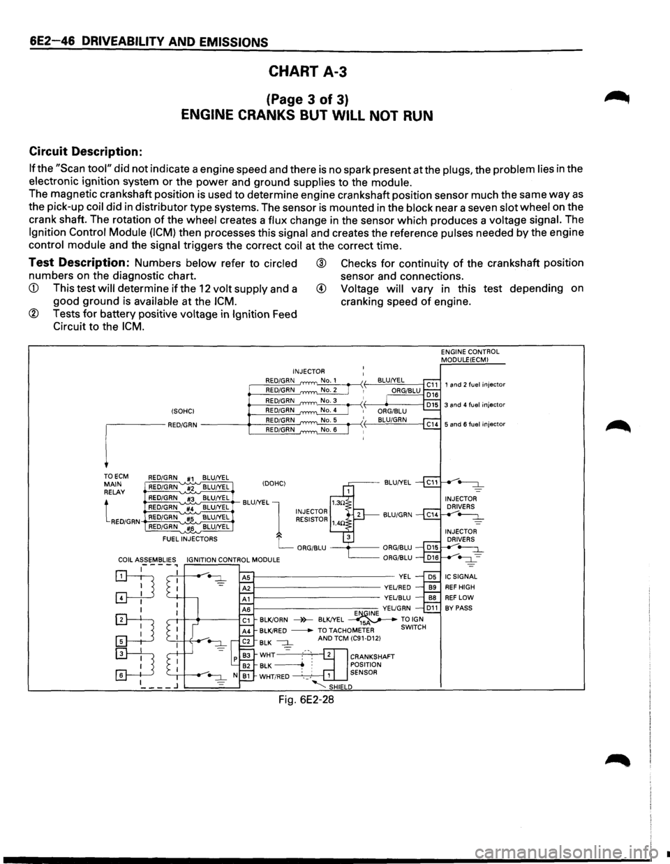
Circuit Description:
If the "Scan tool" did not indicate a engine speed and there is no spark present at the plugs, the problem lies in the
electronic ignition system
or the power and ground supplies to the module.
The magnetic crankshaft position is used to determine engine crankshaft position sensor much the same way as
the pick-up coil did in distributor type systems. The sensor is mounted in the block near a seven slot wheel on the
crank shaft. The rotation
of the wheel creates a flux change in the sensor which produces a voltage signal. The
Ignition Control Module (ICM) then processes this signal and creates the reference pulses needed by the engine
control module and the signal triggers the correct coil at the correct time.
Test Description: Numbers below refer to circled ® Checks for continuity of the crankshaft position
numbers on the diagnostic chart. sensor and connections.
available at the ICM. cranking speed of engine.
® Tests for battery positive voltage in Ignition Feed
Circuit to the
ICM.
TO ECM RED/GRN #1 BLU/YEL MAIN RELAY
tRED/GRN
RED/GRN #2 BLU/YEL
RED/GRN #3 BLU/YEL
RED/GRN '"#4 BLU/YEL RED/GRN #5 BLU/YEL RED/GRN #6 BLU/YEL
FUEL
INJECTORS INJECTOR
RED/GRN RED/GRN RED/GRN
E"'QINE YELJGRN D11 BLK!ORN ----)>--BLK!YEL _____..,-~ TO IGN BLK!RED
-TO TACHOMETER SWITCH BLK --:::J_ AND TCM (C91-D12)
WHT2cl]= :-·-, 2 CRANKSHAFT BLK ~ : POSITION WHT/RED · __ ,' 1 SENSOR
'-;SHIELD
Fig. 6E2-28
ENGINE CONTROL
MODULEIECM)
1 and 2 fuel injector
•