ABS ISUZU TROOPER 1995 Workshop Manual
[x] Cancel search | Manufacturer: ISUZU, Model Year: 1995, Model line: TROOPER, Model: ISUZU TROOPER 1995Pages: 1928
Page 488 of 1928
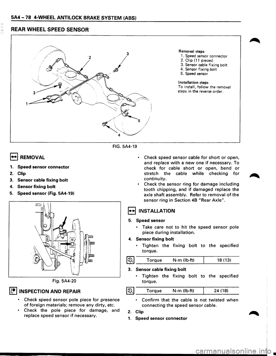
5A4-78 4-WHEEL ANTILOCK BRAKE SYSTEM (ABS)
REAR WHEEL SPEED SENSOR
3 Removal steps
2
/
1. Speed sensor connector 2. Clip (11 pieces)
3.
Sensor cable fixing bolt 4. Sensor fixing bolt 5. Speed sensor
j
/
Installation steps
To
install, follow the removal
steps in the reverse order.
FIG. 5A4-19
1+•1 REMOVAL
1. Speed sensor connector
2. Clip
3. Sensor cable fixing bolt
4. Sensor fixing bolt
5. Speed sensor (Fig. 5A4-19)
Fig.
5A4-20
IL•ItNSPECTION AND REPAIR
• Check speed sensor pole piece for presence
of foreign materials; remove any dirty, etc.
• Check the pole piece for damage, and
replace speed sensor if necessary.
• Check speed sensor cable for short or open,
and
replace with a new one if necessary. To
check
for cable short or open, bend or
stretch the cable while checking for
continuity.
• Check the sensor ring for damage including
tooth chipping, and if damaged replace the
axle shaft assembly. Refer to removal of the
sensor ring in
Section 48 "Rear Axle".
,,..,,INSTALLATION
5. Speed sensor
• Take care not to hit the speed sensor pole
piece during installation.
4. Sensor fixing bolt
• Tighten the fixing bolt to the specified
torque.
I~I ____ T_o_rq~u_e ____ N __ ·m __ O_b·_ft_) __ ~ ____ 18_(_1_3_) __
3. Sensor cable fixing bolt
• Tighten the fixing bolt to the specified
torque.
~~~ Torque N·m (lb.ft) 24 (18)
• Confirm that the cable is not twisted when
connecting the speed sensor cable.
2. Clip
1. Speed sensor connector
•
Page 489 of 1928
ILLUSTRATION
'~ ~··
J -
~
. .
"
~
"f'38~
0
~~ '~
--~ S::S.·f
-~; -~b'
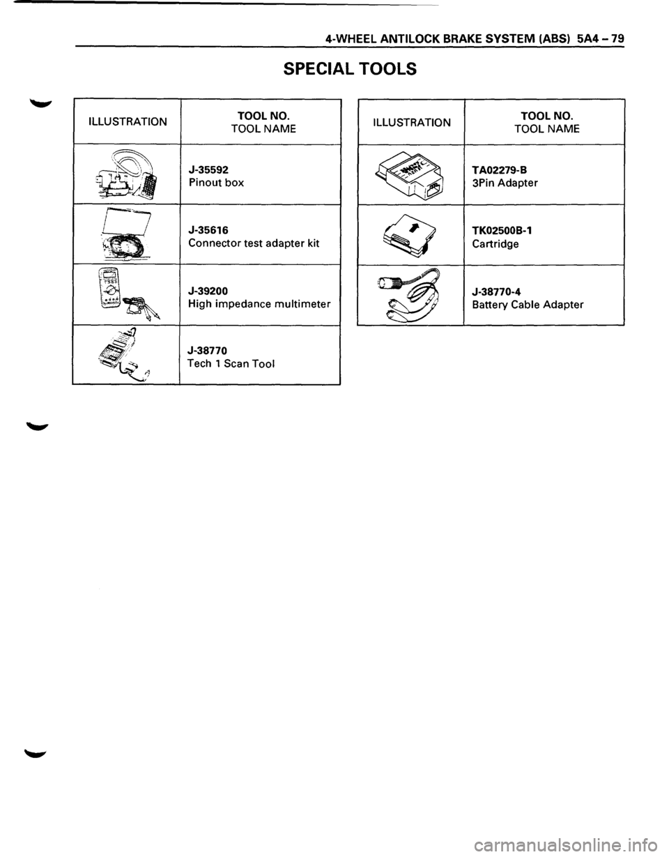
SPECIAL TOOLS
TOOL NO.
TOOL
NAME ILLUSTRATION
J-35592
Pinout box
J-35616
Connector test adapter kit
J-39200
High impedance multimeter
J-38770
Tech 1 Scan Tool
TOOL NO.
TOOL
NAME
TA02279-B
3Pin Adapter
TK02500B-1
Cartridge
J-38770-4 Battery
Cable Adapter
Page 503 of 1928
ENGINE DIAGNOSIS 6-5
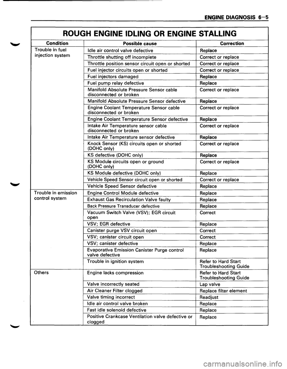
ROUGH ENGINE IDLING OR ENGINE STALLING
Condition Possible cause Correction
Trouble in fuel
Idle air control valve defective Replace
injection system
Throttle shutting
off incomplete Correct or replace
Throttle position sensor circuit open
or shorted Correct or replace
Fuel injector circuits open or shorted Correct or replace
Fuel injectors damaged
Replace
Fuel pump relay defective Replace
Manifold Absolute Pressure Sensor
cable Correct or replace
disconnected
or broken
Manifold Absolute Pressure Sensor defective
Replace
Engine Coolant Temperature Sensor cable Correct
or replace
disconnected
or broken
Engine Coolant Temperature Sensor defective
Replace
Intake Air Temperature sensor cable Correct or replace
disconnected
or broken
Intake Air Temperature sensor defective
Replace
Knock Sensor
(KS) circuits open or shorted
Correct or replace
(DOHC only)
KS defective (DOHC only) Replace
KS Module circuits open or ground
Correct or replace
(DOHC only)
KS Module defective (DOHC only) Replace
Vehicle Speed Sensor circuit open or shorted
Correct or replace
Vehicle Speed Sensor defective
Replace
Trouble in emission
Engine Control Module defective
Replace
control system
Exhaust Gas Recirculation
Valve faulty
Replace
Back Pressure Transducer defective
Replace
Vacuum Switch Valve (VSV); EGR circuit
Correct
open
VSV; EGR defective Replace
Canister purge
VSV circuit open
Correct
VSV; canister circuit open
Correct
VSV; canister defective
Replace
Evaporative Emission Canister Purge control
Replace
valve defective
Trouble in ignition system
Refer
to Hard Start
Troubleshooting Guide
Others Engine lacks compression
Refer to Hard Start
Troubleshooting Guide
Valve incorrectly seated
Lap valve
Air Cleaner Filter clogged
Replace filter element
Valve timing incorrect
Readjust
Idle air control valve broken
Replace
Fast
idle solenoid defective
Replace
Positive Crankcase Ventilation valve defective
or Replace
clogged
Page 504 of 1928
6-6 ENGINE DIAGNOSIS
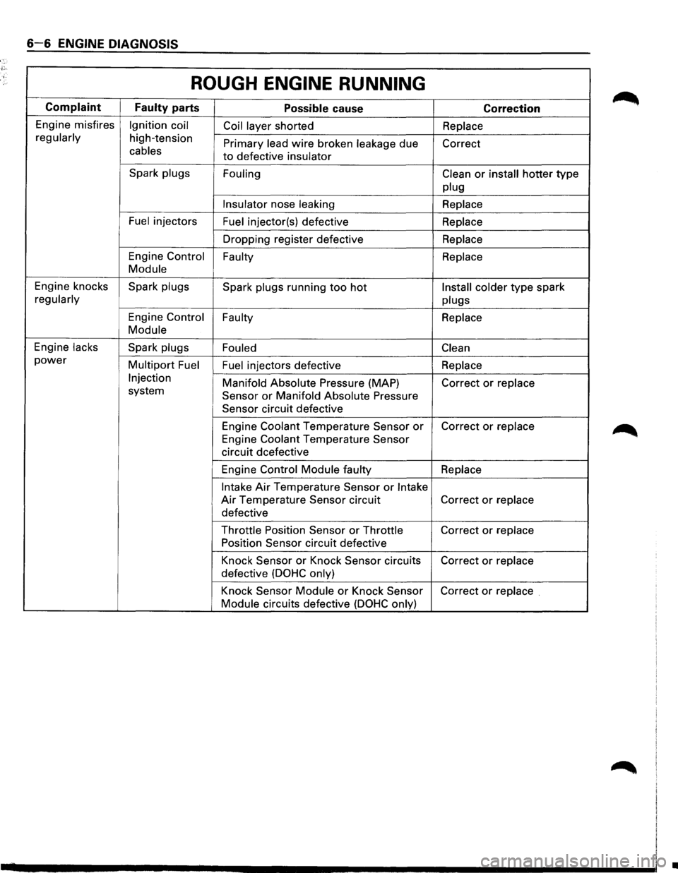
ROUGH ENGINE RUNNING
Complaint
Faulty parts Possible cause Correction
Engine misfires Ignition coil
Coil layer shorted Replace
regularly
high-tension Primary lead wire broken leakage due
Correct cables to defective insulator
Spark plugs
Fouling Clean
or install hotter type
plug
Insulator
nose leaking Replace
Fuel
injectors Fuel injector(s) defective Replace
Dropping register defective Replace
Engine Control
Faulty Replace
Module
Engine knocks Spark plugs
Spark plugs running too hot Install colder type spark
regularly
plugs
Engine Control Faulty
Replace
Module
Engine lacks Spark plugs
Fouled Clean
power Multipart Fuel
Fuel injectors defective Replace
Injection Manifold Absolute Pressure (MAP)
Correct or replace system Sensor or Manifold Absolute Pressure
Sensor
circuit defective
Engine
Coolant Temperature Sensor or Correct or replace
Engine Coolant Temperature Sensor
circuit dcefective
Engine
Control Module faulty Replace
Intake
Air Temperature Sensor or Intake
Air Temperature Sensor circuit Correct or replace
defective
Throttle Position Sensor or Throttle Correct or replace
Position Sensor
circuit defective
Knock
Sensor or Knock Sensor circuits Correct or replace
defective (DOHC only)
Knock Sensor Module or Knock Sensor Correct or replace .
Module
circuits defective (DOHC only)
•
Page 505 of 1928
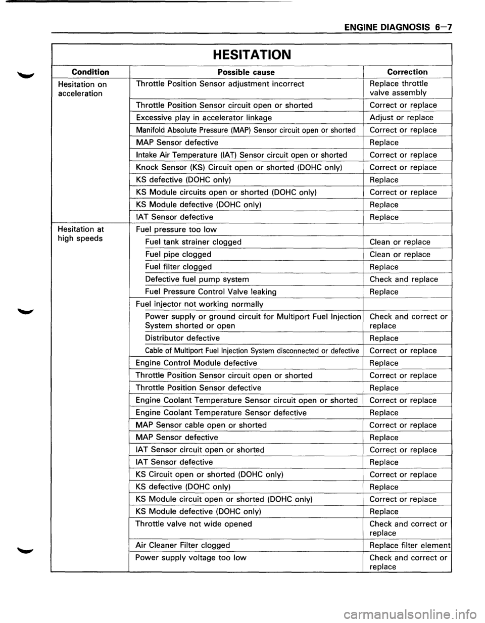
ENGINE DIAGNOSIS 6-7
HESITATION
Condition Possible cause Correction
Hesitation on Throttle
Position Sensor adjustment incorrect Replace
throttle
acceleration valve
assembly
Throttle Position Sensor circuit open
or shorted Correct
or replace
Excessive play in accelerator linkage
Adjust or replace
Manifold Absolute
Pressure (MAP) Sensor circuit open or shorted Correct or replace
MAP Sensor defective Replace
Intake Air
Temperature (IAT) Sensor circuit open or shorted Correct or replace
Knock Sensor
(KS) Circuit open or shorted (DOHC only) Correct or replace
KS defective (DOHC only) Replace
KS Module circuits open or shorted (DOHC only) Correct or replace
KS Module defective (DOHC only) Replace
IAT Sensor defective Replace
Hesitation at
Fuel pressure
too low
high speeds
Fuel tank strainer clogged Clean or replace
Fuel pipe clogged
Clean or replace
Fuel filter clogged
Replace
Defective fuel
pump system Check and replace
Fuel Pressure Control Valve leaking Replace
Fuel injector
not working normally
Power supply or ground circuit for Multipart Fuel Injection Check and correct or
System shorted or open
replace
Distributor defective Replace
Cable of Multipart Fuel Injection System disconnected or defective Correct or replace
Engine Control Module defective Replace
Throttle Position Sensor circuit open
or shorted Correct or replace
Throttle Position Sensor defective Replace
Engine Coolant Temperature Sensor circuit open
or shorted Correct or replace
Engine Coolant Temperature Sensor defective Replace
MAP Sensor cable open
or shorted Correct or replace
MAP Sensor defective
Replace
IAT Sensor circuit open or shorted
Correct or replace
IAT Sensor defective Replace
KS Circuit open or shorted (DOHC only)
Correct or replace
KS defective (DOHC only) Replace
KS Module circuit open or shorted (DOHC only) Correct or replace
KS Module defective (DOHC only) Replace
Throttle valve
not wide opened
Check and correct or
replace
Air Cleaner Filter clogged
Replace filter element
Power supply voltage
too low Check and correct or
replace
Page 506 of 1928
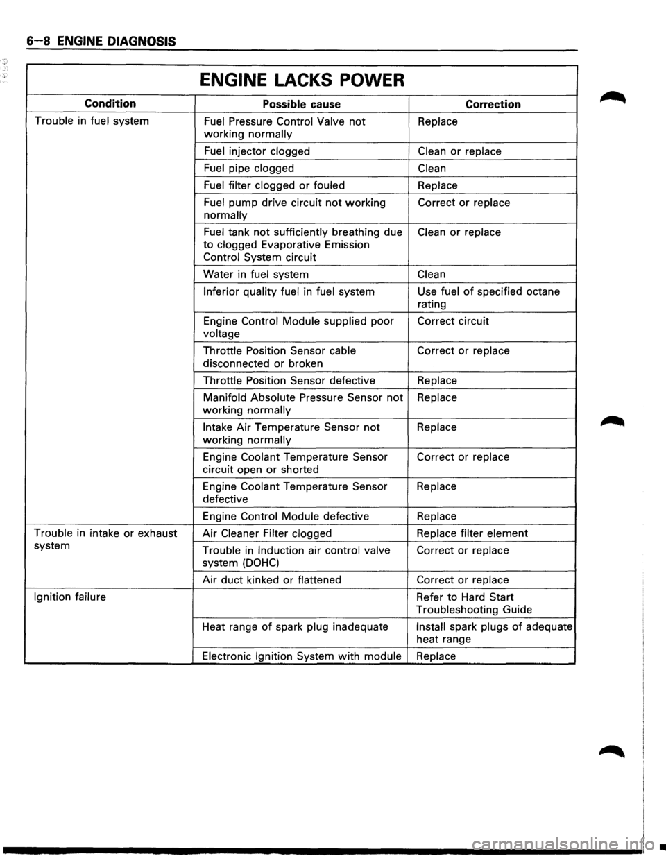
6-8 ENGINE DIAGNOSIS
ENGINE LACKS POWER
Condition
Possible cause Correction
Trouble in fuel system Fuel Pressure Control Valve not Replace
working normally
Fuel
injector clogged Clean or replace
Fuel
pipe clogged Clean
Fuel filter clogged
or fouled Replace
Fuel
pump drive circuit not working Correct or replace
normally
Fuel tank not sufficiently breathing due Clean or replace
to clogged Evaporative Emission
Control System circuit
Water in
fuel system Clean
Inferior quality fuel
in fuel system Use fuel of specified octane
rating
Engine
Control Module supplied poor Correct circuit
voltage
Throttle
Position Sensor cable Correct or replace
disconnected or broken
Throttle Position Sensor defective Replace
Manifold Absolute
Pressure Sensor not Replace
working normally
Intake Air Temperature Sensor not Replace
working normally
Engine Coolant Temperature Sensor Correct or replace
circuit open or shorted
Engine
Coolant Temperature Sensor Replace
defective
Engine
Control Module defective Replace
Trouble
in intake or exhaust Air Cleaner Filter clogged Replace filter element
system Trouble in Induction air control valve Correct or replace
system (DOHC)
Air duct kinked or flattened Correct or replace
Ignition failure
Refer to Hard Start
Troubleshooting Guide
Heat range
of spark plug inadequate Install spark plugs of adequate
heat range
Electronic Ignition System with module Replace
•
Page 510 of 1928
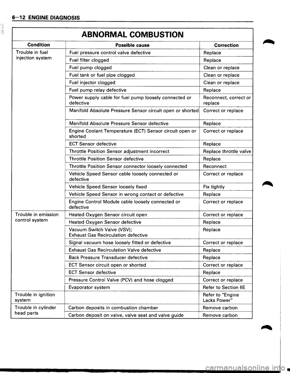
6-12 ENGINE DIAGNOSIS
ABNORMAL COMBUSTION
Condition
Possible cause Correction
Trouble in fuel Fuel pressure control valve defective Replace
injection system
Fuel filter clogged
Replace
Fuel pump clogged Clean or replace
Fuel tank
or fuel pipe clogged Clean or replace
Fuel injector clogged Clean or replace
Fuel
pump relay defective
Replace
Power supply cable for fuel pump loosely connected or Reconnect, correct or
defective
replace
Manifold Absolute
Pressure Sensor circuit open or shorted Correct or replace
Manifold Absolute
Pressure Sensor defective Replace
Engine Coolant Temperature
(ECT) Sensor circuit open or Correct or replace
shorted
ECT Sensor defective
Replace
Throttle
Position Sensor adjustment incorrect Replace throttle valve
Throttle
Position Sensor defective
Replace
Throttle
Position Sensor connector loosely connected Reconnect
Vehicle Speed Sensor cable loosely connected or Correct or replace
defective
Vehicle Speed Sensor loosely fixed Fix tightly
Vehicle Speed Sensor in wrong contact or defective Replace
Engine Control Module cable
loosely connected or Correct or replace
defective
Trouble in emission
Heated
Oxygen Sensor circuit open Correct or replace
control system
Heated
Oxygen Sensor defective Replace
Vacuum Switch
Valve (VSV); Replace
Exhaust Gas Recirculation defective
Signal vacuum hose loosely fitted or defective Correct or replace
Exhaust Gas Recirculation
Valve defective Replace
Back
Pressure Transducer defective Replace
ECT Sensor circuit open or shorted Correct or replace
ECT Sensor defective Replace
Pressure Control Valve (PCV) and hose clogged Correct or replace
Evaporator system
Refer
to Section 6E
Trouble in ignition
Refer to "Engine
system Lacks
Power"
Trouble in cylinder
Carbon deposits in combustion chamber Remove carbon
head parts
Carbon deposit on valve,
valve seat and valve guide
Remove carbon
•
Page 513 of 1928
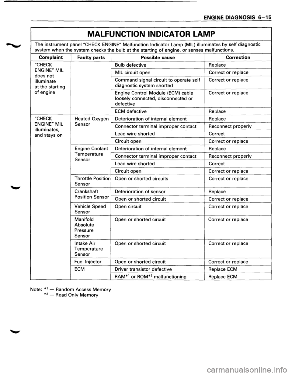
ENGINE DIAGNOSIS 6-15
MALFUNCTION INDICATOR LAMP
The instrument panei"CHECK ENGINE" Malfunction Indicator Lamp (MIL) illuminates by self diagnostic
system
when the system checks the bulb at the starting of engine, or senses malfunctions.
Complaint
Faulty parts
"CHECK
ENGINE" MIL
does not
illuminate
at the starting
of engine
"CHECK Heated Oxygen
ENGINE" MIL Sensor
illuminates,
and stays on
Engine
Coolant
Temperature Sensor
Throttle Position
Sensor
Crankshaft Position Sensor
Vehicle Speed
Sensor
Manifold
Absolute
Pressure Sensor
Intake Air
Temperature Sensor
Fuel Injector
ECM
Note: *1
-Random Access Memory
*2
-Read Only Memory
Possible cause Correction
Bulb defective Replace
MIL
circuit open Correct or replace
Command signal
circuit to operate self Correct or replace
diagnostic system shorted
Engine
Control Module (ECM) cable Correct or replace
loosely
connected, disconnected or
defective
ECM defective Replace
Deterioration of internal element Replace
Connector terminal improper contact Reconnect properly
Lead wire shorted Correct
Circuit
open Correct or replace
Deterioration of internal element Replace
Connector terminal improper contact Reconnect properly
Lead wire shorted Correct
Circuit
open Correct or replace
Open
or shorted circuits Correct or replace
Deterioration of sensor Replace
Open
or shorted circuit Correct or replace
Open
circuit Correct or replace
Open
or shorted circuit Correct or replace
Open
or shorted circuit Correct or replace
Open
or shorted circuit Correct or replace
Driver transistor defective Replace ECM
RAM*1 or ROM*2 malfunctioning Replace ECM
Page 566 of 1928
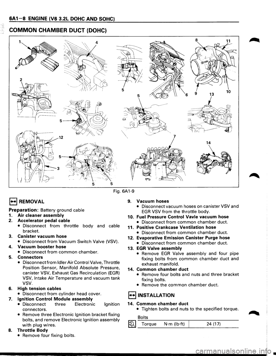
6A1-8 ENGINE (V6 3.2L DOHC AND SOHC)
COMMON CHAMBER DUCT (DOHC)
8
11
5
5
6
7
14
5 5
Fig. 6A1-9
E) REMOVAL
Preparation: Battery ground cable
1. Air cleaner assembly
2. Accelerator pedal cable
• Disconnect from throttle body and cable
bracket.
3. Canister vacuum hose
• Disconnect from Vacuum Switch Valve (VSV).
4. Vacuum booster hose
• Disconnect from common chamber.
5. Connectors
• Disconnect from Idler Air Control Valve, Throttle
Position Sensor, Manifold Absolute Pressure,
canister VSV, Exhaust Gas Recirculation (EGR)
VSV, Intake Air Temperature and vacuum tank
vsv.
6. High tension cables
• Disconnect from cylinder head cover.
7. Ignition Control Module assembly
• Disconnect three Electronic Ignition
connectors.
• Remove three Electronic Ignition bracket fixing
bolts, and remove Electronic Ignition assembly
with plug wires.
8. Throttle Body
• Remove four fixing bolts.
9. Vacuum hoses
• Disconnect vacuum hoses on canister VSV and
EGR VSV from the throttle body.
10. Fuel Pressure Control Vavle vacuum hose
• Disconnect from common chamber duct.
11. Positive Crankcase Ventilation hose
• Disconnect from common chamber duct.
12. Evaporative Emission Canister Purge hose
• Disconnect from common chamber duct.
13. EGR Valve assembly
• Remove EGR Valve assembly and four pipe
fixing bolts from common chamber duct and
exhaust manifold.
14. Common chamber duct
• Remove four bolts and nuts and three bracket
fixing bolts.
• Remove the common chamber duct.
l·u·IINSTALLATION
14. Common chamber duct
• Tighten bolts and nuts to the specified torque.
Bolts
~~~ Torque N·m (lb·ft) 24 (17)
•
Page 568 of 1928
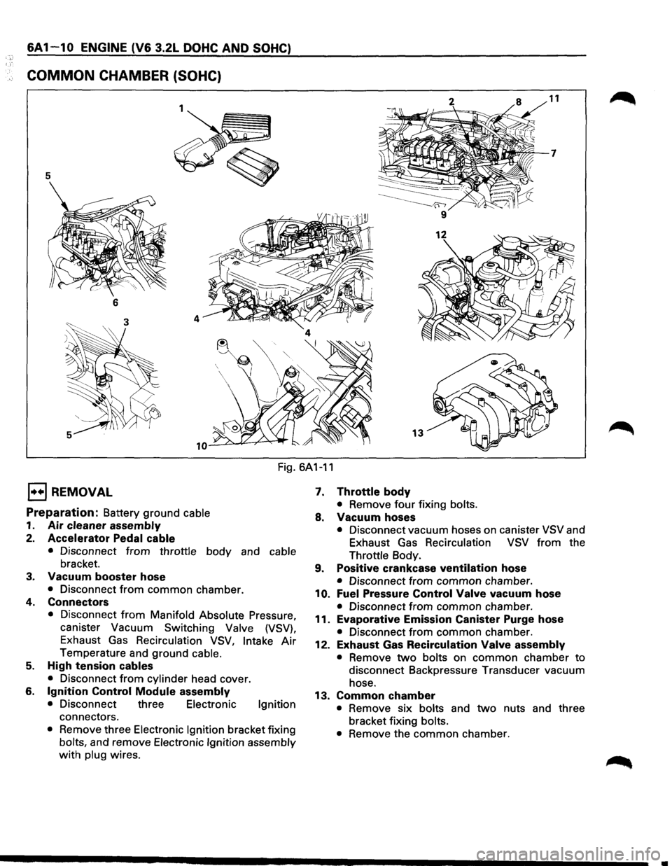
6A 1 1 0 ENGINE (V6 3.2L DOHC AND SOHC)
COMMON CHAMBER (SOHC)
5
6
13
Fig. 6A1-11
1••1 REMOVAL
Preparation: Battery ground cable
1. Air cleaner assembly
2. Accelerator Pedal cable
• Disconnect from throttle body and cable
bracket.
3. Vacuum booster hose
• Disconnect from common chamber.
4. Connectors
• Disconnect from Manifold Absolute Pressure,
canister Vacuum Switching
Valve (VSV),
Exhaust Gas Recirculation VSV, Intake Air
Temperature and ground cable.
5. High tension cables
• Disconnect from cylinder head cover.
6. Ignition Control Module assembly
• Disconnect three Electronic Ignition
connectors.
• Remove three Electronic Ignition bracket fixing
bolts, and remove Electronic Ignition assembly
with plug wires.
7. Throttle body
• Remove four fixing bolts.
8. Vacuum hoses
• Disconnect vacuum hoses on canister VSV and
Exhaust Gas
Recirculation VSV from the
Throttle Body.
9. Positive crankcase ventilation hose
• Disconnect from common chamber.
10. Fuel Pressure Control Valve vacuum hose
• Disconnect from common chamber.
11. Evaporative Emission Canister Purge hose
• Disconnect from common chamber.
12. Exhaust Gas Recirculation Valve assembly
• Remove two bolts on common chamber to
disconnect Backpressure Transducer vacuum
hose.
13. Common chamber
• Remove six bolts and two nuts and three
bracket fixing
bolts.
•
Remove the common chamber.