ABS ISUZU TROOPER 1995 Workshop Manual
[x] Cancel search | Manufacturer: ISUZU, Model Year: 1995, Model line: TROOPER, Model: ISUZU TROOPER 1995Pages: 1928
Page 455 of 1928
![ISUZU TROOPER 1995 Workshop Manual CHART A-5, TA-5 I):Eet<(] I TECH 1 I
5) BRAKING SOUND (FROM HYDRAULIC UNIT) IS HEARD WHILE NOT BRAKING
IS THIS THE FIRST VEHICLE START AFTER ENGINE
START? AND IS VEHICLE SPEED UNDER 10 KM/H](/img/61/57183/w960_57183-454.png "ISUZU TROOPER 1995 Workshop Manual CHART A-5, TA-5 I):Eet<(] I TECH 1 I
5) BRAKING SOUND (FROM HYDRAULIC UNIT) IS HEARD WHILE NOT BRAKING
IS THIS THE FIRST VEHICLE START AFTER ENGINE
START? AND IS VEHICLE SPEED UNDER 10 KM/H")
CHART A-5, TA-5 I):Eet<(] I TECH 1 I
5) BRAKING SOUND (FROM HYDRAULIC UNIT) IS HEARD WHILE NOT BRAKING
IS THIS THE FIRST VEHICLE START AFTER ENGINE
START? AND IS VEHICLE SPEED UNDER 10 KM/H
(6MPH)?
WHEN
DID IT OCCUR? 1. AT THE TIME OF SHIFT DOWN OR CLUTCH OPERATION 2. AT THE TIME OF LOW J.l DRIVE (ICE OR SNOW ROAD) OR ROUGH ROAD DRIVE 3. AT THE TIME OF HIGH-SPEED TURN 4. AT THE TIME OF PASSING CURB 5. AT THE TIME OF OPERATING ELECTRICAL
EQUIPMENT SWITCHES
6. AT THE TIME OF RACING THE ENGINE (OVER
5000 RPM)
IS THERE PLAY IN EACH SENSOR/WHEEL
SPEED SENSOR RINGS?
•
CHECK HARNESS/CONNECTOR FOR SUSPECTED
DISCONNECTION
• IF NO DISCONNECTION IS FOUND,
REPLACE EBCM
IT IS SELF-CHECKING SOUND NORMAL
UNDER ANY ONE CONDITION ABOVE, ABS MAY SOMETIME BE ACTUATED EVEN WHEN BRAKE
PEDAL IS NOT APPLIED
11 = Friction Unit
Page 456 of 1928
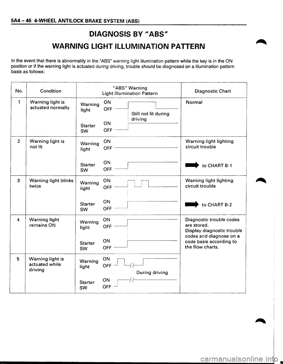
5A4-46 4-WHEEL ANTILOCK BRAKE SYSTEM (ABS)
DIAGNOSIS BY II ABS,
WARNING LIGHT ILLUMINATION PATTERN
In the event that there is abnormality in the "ASS" warning light illumination pattern while the key is in the ON
position or if the warning light is actuated during driving, trouble should be diagnosed on a illumination pattern
basis as
follows:
No.
Condition "ABS" Warning Diagnostic Chart
Light Illumination Pattern
1 Warning light is ON Normal Warning I I actuated normally light OFF ' , Still not lit during
Starter ON : driving
sw OFF
2 Warning light is
Warning ON Warning light lighting
not lit light OFF circuit trouble
ON .... to CHART 8-1
Starter I sw OFF
3 Warning light blinks Warning ON Warning light lighting
twice light OFF circuit trouble
:
ON ... to CHART
B-2
Starter
sw OFF
4 Warning light ON Diagnostic trouble codes Warning J remains ON light OFF are
stored.
Display diagnostic trouble ' codes and diagnose on a
Starter
ON I code basis according to
sw OFF the flow charts.
5 Warning light is ON~ Warning actuated while light OFF driving During driving
ONr(l Starter
sw OFF
Page 457 of 1928
4-WHEEL ANTILOCK BRAKE SYSTEM (ASS) 5A4-47
DIAGNOSTIC TROUBLE CODES (DTCs)
When the warning light in the meter remains ON, the EBCM stores the fault identification and disables the
.........,.. ABS.
1. How to display and erase DTCs:
NOTE:
• If DTCs are not displayed, harness BB 14 may be disconnected. Repair the harness and try DTC
display again.
• DTCs can be displayed also by TECH 1. For further details, see "MODE F2: TROUBLE CODE" in this
section.
(1)
How to start DTC display:
• Confirm
that the vehicle has come to a complete stop (with the wheels standing still) and that the
brake pedal is not depressed. (Unless these two condition are satisfied, DTC display cannot be
started.)
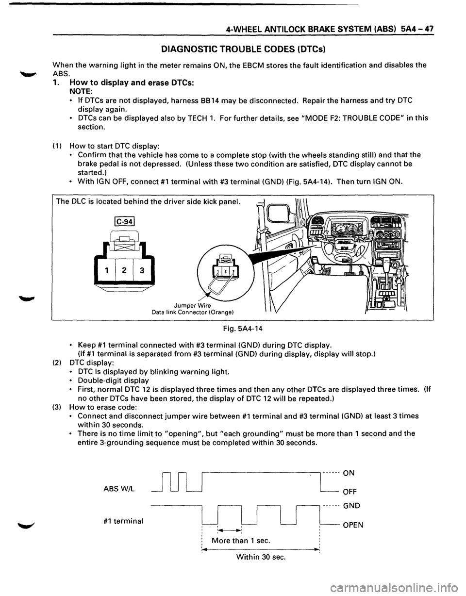
• With IGN OFF, connect #1 terminal with #3 terminal (GND) (Fig. 5A4-14). Then turn IGN ON.
The DLC is located behind the driver side kick panel.
1 2 3
Jumper Wire Data link Connector (Orange}
Fig. 5A4-14
• Keep #1 terminal connected with #3 terminal (GND) during DTC display.
(If
#1 terminal is separated from #3 terminal (GND) during display, display will stop.)
(2) DTC display:
•
DTC is displayed by blinking warning light.
•
Double-digit display
•
First, normal DTC 12 is displayed three times and then any other DTCs are displayed three times. (If
no other DTCs have been stored, the display of DTC 12 will be repeated.)
(3) How to erase code:
• Connect and disconnect jumper wire between #1 terminal and #3 terminal (GND) at least 3 times
within 30 seconds.
• There is no time limit to "opening", but "each grounding" must be more than 1 second and the
entire 3-grounding sequence must be completed within 30 seconds.
ABS W/L
#1 terminal
r---------------, ------ON
More than 1 sec.
OFF
.--------, ------ GND
OPEN
' ,._ _________ ,_:
Within 30 sec.
Page 458 of 1928
5A4-48 4-WHEEL ANTILOCK BRAKE SYSTEM (ABS)
(4) Notes
• If the following should occurs during Diagnostic Trouble Code (DTC) display the display will be
discontinued.
After initial check, the status that is under the control of ABS will be returned:
- The vehicle starts (The wheels turn)
or the brake pedal is depressed.
• Up to 3 different codes can be stored.
• If the ABS should turn OFF due to an intermittent defect, the system will be restored at the next key
cycle,
if the initial check finds no abnormality (when IGN is switched from OFF to ON).
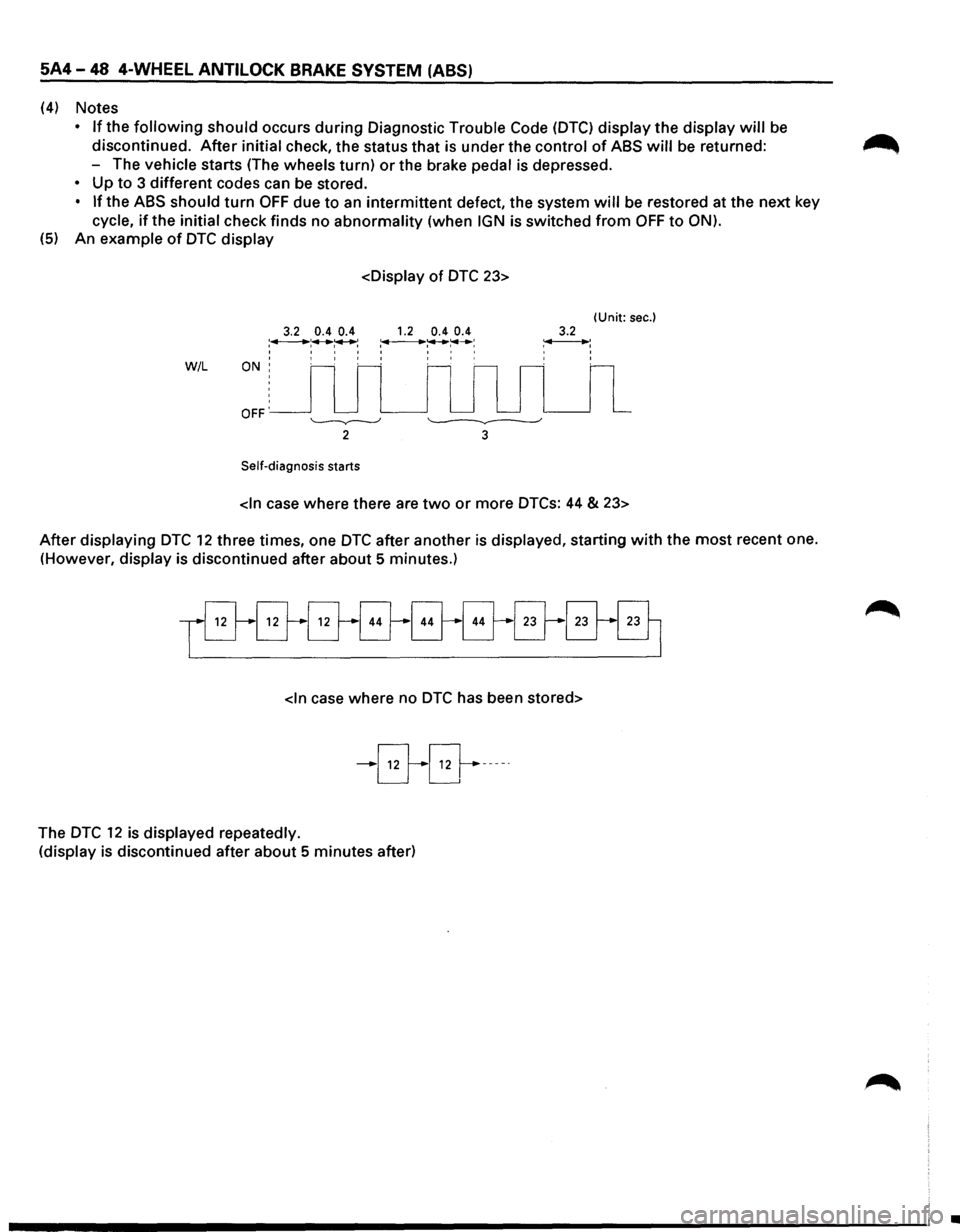
(5) An example of DTC display
3.2 0.4 0.4 :.,..___......: .......... ~: I I I I
W/L ON: I I t
OFF'
Self-diagnosis starts
1.2 0.4 0.4 ~:+-+:---__.,..: I I I I I I I I
(Unit: sec.) 3.2 ~: ' ' ' '
After displaying
DTC 12 three times, one DTC after another is displayed, starting with the most recent one.
(However, display is discontinued after about 5 minutes.)
-B-0-----·
The DTC 12 is displayed repeatedly.
(display is discontinued after about 5 minutes after)
•
Page 459 of 1928
4-WHEEL ANTILOCK BRAKE SYSTEM (ABS) 5A4-49
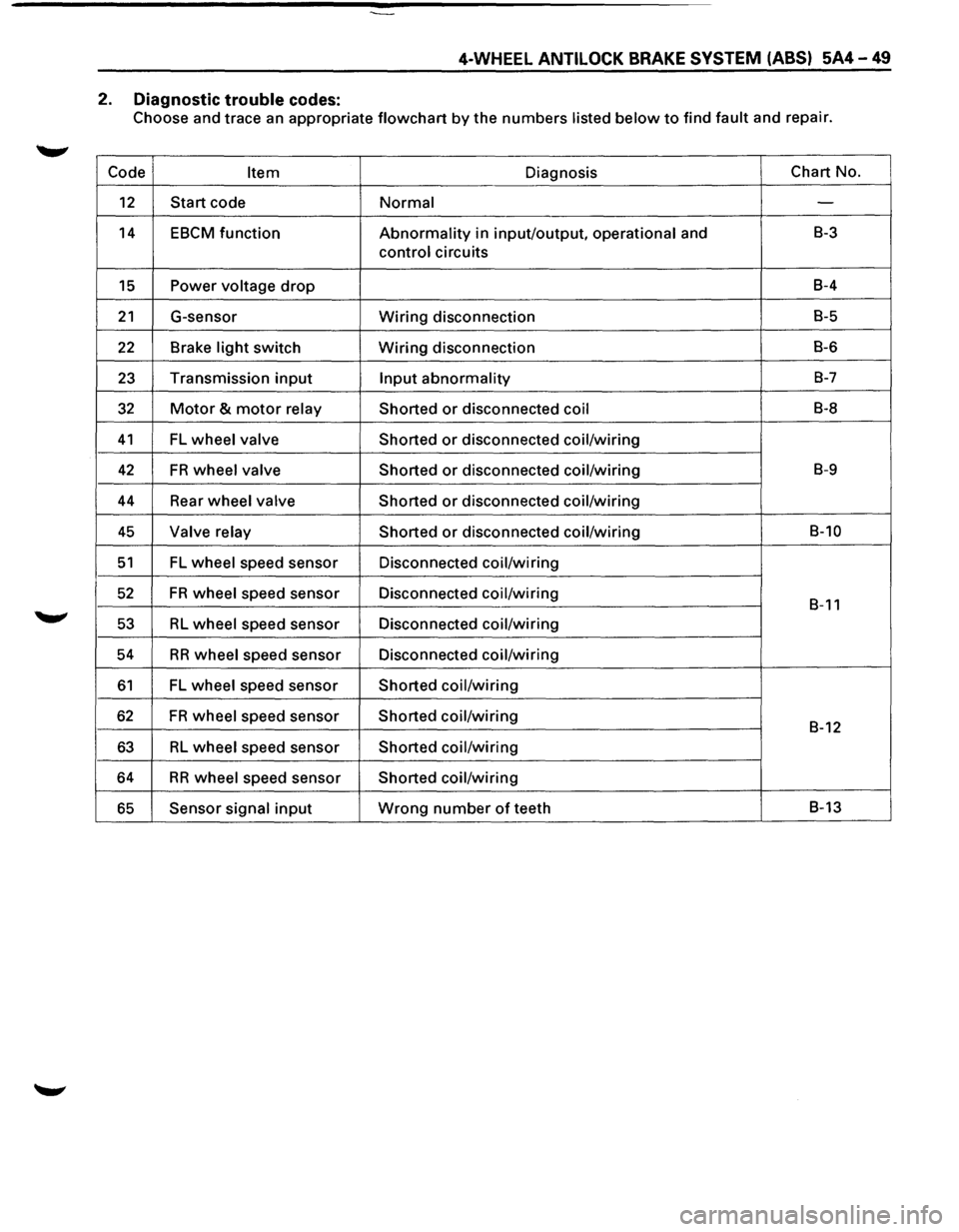
2. Diagnostic trouble codes:
Choose and trace an appropriate flowchart by the numbers listed below to find fault and repair.
Code
Item Diagnosis Chart
No.
12 Start code Normal -
14 EBCM function Abnormality in input/output, operational and B-3
control circuits
15 Power voltage drop B-4
21 G-sensor Wiring disconnection B-5
22 Brake light switch Wiring disconnection B-6
23 Transmission input Input abnormality B-7
32 Motor & motor relay
Shorted or disconnected coil B-8
41 FL wheel valve
Shorted or disconnected coil/wiring
42 FR wheel valve
Shorted or disconnected coil/wiring B-9
44 Rear wheel valve Shorted or disconnected coil/wiring
45 Valve relay Shorted or disconnected coil/wiring B-10
51 FL wheel speed sensor Disconnected coil/wiring
52 FR wheel speed sensor Disconnected coil/wiring B-11
53 RL wheel speed sensor Disconnected coil/wiring
54
RR wheel speed sensor Disconnected coil/wiring
61 FL wheel speed sensor Shorted coil/wiring
62 FR wheel speed sensor Shorted coil/wiring B-12
63 RL wheel speed sensor Shorted coil/wiring
64 RR wheel speed sensor Shorted coil/wiring
65 Sensor signal input Wrong number of teeth B-13
Page 460 of 1928
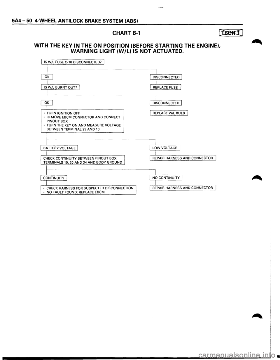
5A4-50 4-WHEEL ANTILOCK BRAKE SYSTEM (ABS)
CHART B-1
WITH THE KEY IN THE ON POSITION (BEFORE STARTING THE ENGINE),
WARNING LIGHT
{W/L) IS NOT ACTUATED.
IS W/L FUSE C-10 DISCONNECTED? j
I
IS W/L BURNT OUT? I
I
• TURN IGNITION OFF
• REMOVE EBCM CONNECTOR AND CONNECT PINOUT BOX
• TURN THE KEY ON AND MEASURE VOLTAGE BETWEEN TERMINAL 29 AND 10
I
I
BATTERYVOLTAGE I
I
CHECK CONTINUITY BETWEEN PINOUT BOX I TERMINALS 10, 20 AND 34 AND BODY GROUND
l
I CONTINUITY I
I • CHECK HARNESS FOR SUSPECTED DISCONNECTION I • NO FAULT FOUND: REPLACE EBCM
I
I
DISCONNECTED I
I L REPLACE FUSE J
I L DISCONNECTED J
I I REPLACE W/L BULB I
I
I
LOWVOLTAGE I
I
I
REPAIR HARNESS AND CONNECTOR I
I
I
NO CONTINUITY I
I I REPAIR HARNESS AND CONNECTOR I
•
Page 461 of 1928
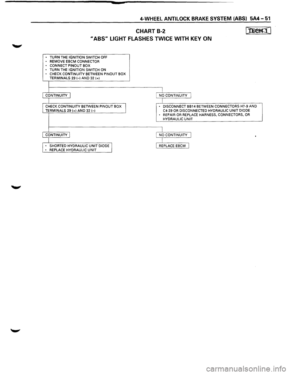
4-WHEEL ANTILOCK BRAKE SYSTEM (ABS) 5A4-51
CHART B-2 [JECK¢(1
II ABS11 LIGHT FLASHES TWICE WITH KEY ON
• TURN THE IGNITION SWITCH OFF • REMOVE EBCM CONNECTOR
• CONNECT PINOUT BOX
• TURN THE IGNITION SWITCH ON CHECK CONTINUITY BETWEEN PINOUT BOX
TERMINALS 29 HAND 32 (+)
I CONTINUITY I NO CONTINUITY I
I CHECK CONTINUITY BETWEEN PINOUT BOX
I
DISCONNECT BB14 BETWEEN CONNECTORS H7-9 AND TERMINALS 29 (+)AND 32 H C4-29 OR DISCONNECTED
HYDRAULIC UNIT DIODE
• REPAIR OR REPLACE HARNESS, CONNECTORS, OR HYDRAULIC UNIT
I CONTINUITY I NO CONTINUITY I .
I • SHORTED HYDRAULIC UNIT DIODE I REPLACE EBCM I • REPLACE HYDRAULIC UNIT
Page 462 of 1928
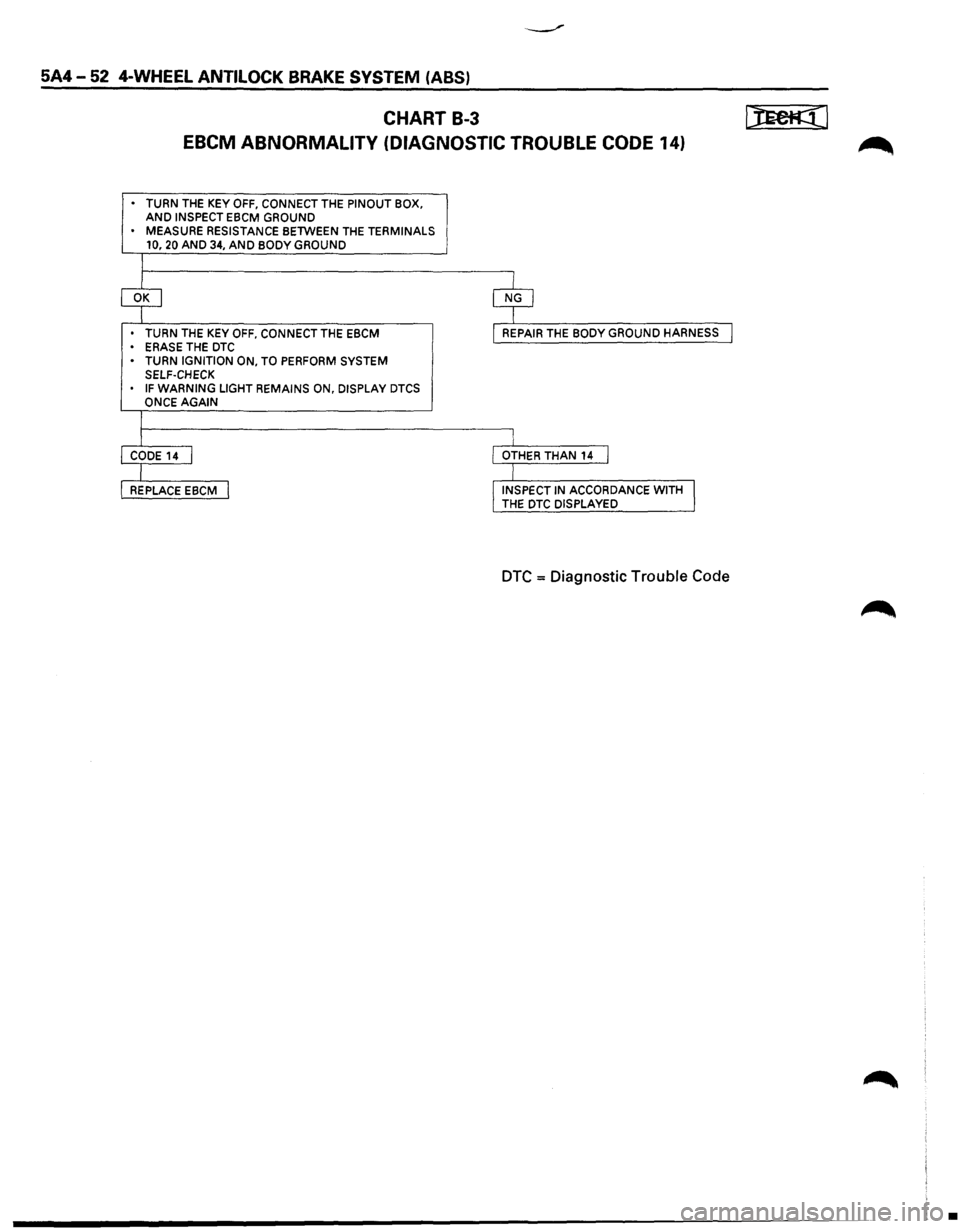
5A4-52 4-WHEEL ANTILOCK BRAKE SYSTEM (ABS)
CHART B-3 ~I
EBCM ABNORMALITY (DIAGNOSTIC TROUBLE CODE 14)
• TURN THE KEY OFF, CONNECT THE PINOUT BOX. AND INSPECT EBCM GROUND
• MEASURE RESISTANCE BETWEEN THE TERMINALS
10, 20 AND 34, AND BODY GROUND
T
~ $
• TURN THE KEY OFF, CONNECT THE EBCM
• ERASE THE DTC I REPAIR THE BODY GROUND HARNESS I
• TURN IGNITION ON, TO PERFORM SYSTEM
SELF-CHECK
IF WARNING LIGHT REMAINS ON, DISPLAY DTCS
ONCE AGAIN
I
r I CODE14 I I OTHER THAN
14 I
I I
REPLACE EBCM I !INSPECT IN ACCORDANCE WITH I THE DTC DISPLAYED
DTC = Diagnostic Trouble Code
•
Page 463 of 1928
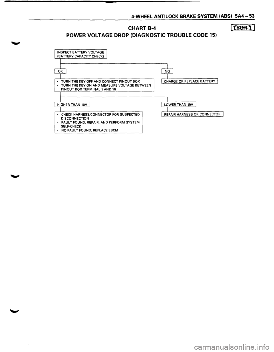
4-WHEEL ANTILOCK BRAKE SYSTEM (ABS) 5A4-53
CHART B-4 ~I
POWER VOLTAGE DROP (DIAGNOSTIC TROUBLE CODE 15)
INSPECT BATTERY VOLTAGE I (BATTERY CAPACITY CHECKI
I
$ ~
• TURN THE KEY OFF AND CONNECT PINOUT BOX I CHARGE OR REPLACE BATTERY I • TURN THE KEY ON AND MEASURE VOLTAGE BETWEEN PINOUT BOX TERMINAL 1 AND 10
I
I
l
HIGHER THAN 10V I I LOWER THAN 10V I
I I
• CHECK HARNESS/CONNECTOR FOR SUSPECTED I REPAIR HARNESS OR CONNECTOR l DISCONNECTION . FAULT FOUND:
REPAIR, AND PERFORM SYSTEM
SELF-CHECK
• NO FAULT FOUND: REPLACE EBCM
Page 464 of 1928
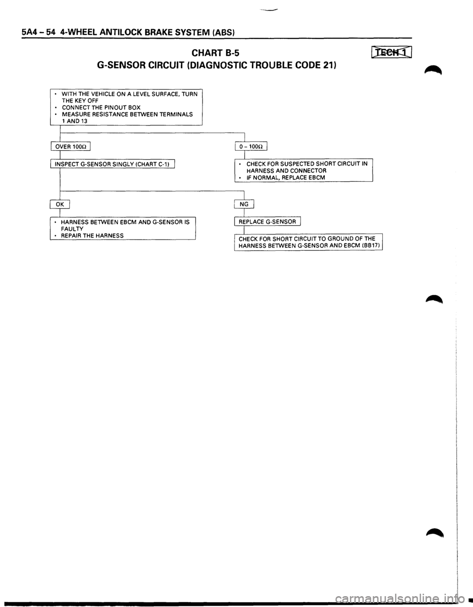
5A4-54 4-WHEEL ANTILOCK BRAKE SYSTEM (ABS)
CHART B-5
G-SENSOR CIRCUIT (DIAGNOSTIC TROUBLE CODE 21)
. WITH THE VEHICLE ON A LEVEL SURFACE, TURN
THE KEY OFF • CONNECT THE PINOUT BOX MEASURE RESISTANCE BETWEEN TERMINALS
1 AND 13
I OVER 100n I o-1oo!l I
I
INSPECTG-SENSOR SINGLY(CHARTC-1) I . CHECK FOR SUSPECTED SHORT CIRCUIT IN
HARNESS AND CONNECTOR . IF NORMAL, REPLACE EBCM
~ $
HARNESS BETWEEN EBCM AND G-SENSOR IS REPLACE G-SENSOR I FAULTY I • REPAIR THE HARNESS
CHECK FOR SHORT CIRCUIT TO GROUND OF THE I HARNESS BETWEEN G-SENSOR AND EBCM (BB17)
•