ABS ISUZU TROOPER 1995 Workshop Manual
[x] Cancel search | Manufacturer: ISUZU, Model Year: 1995, Model line: TROOPER, Model: ISUZU TROOPER 1995Pages: 1928
Page 698 of 1928
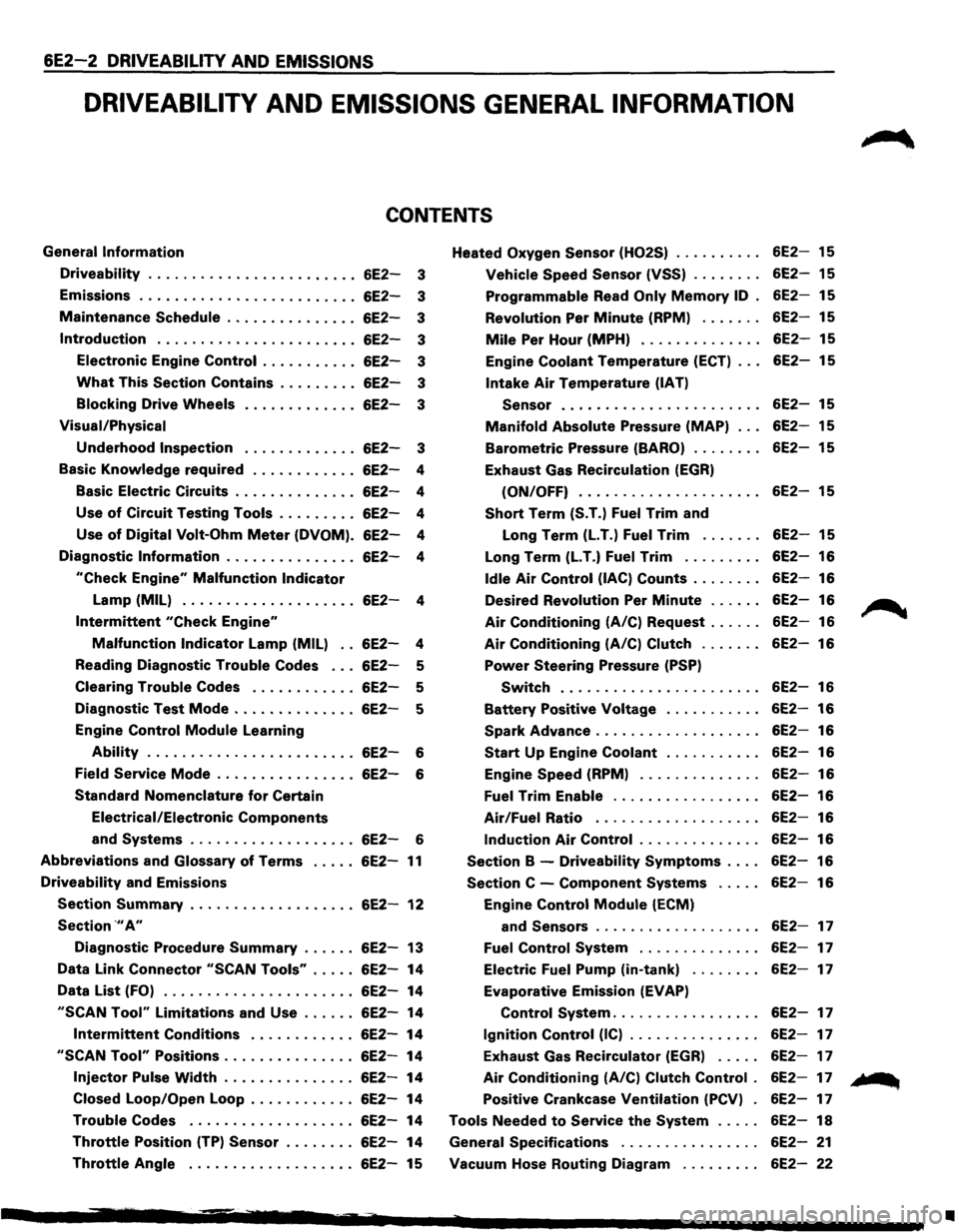
6E2-2 DRIVEABILITY AND EMISSIONS
DRIVEABILITV AND EMISSIONS GENERAL INFORMATION
CONTENTS
General Information
Driveability ....................... .
Emissions
........................ .
Maintenance
Schedule .............. .
Introduction ...................... .
Electronic Engine
Control .......... .
What This Section Contains ........ .
Blocking Drive Wheels
Visual/Physical
Underhood Inspection
6E2-3
6E2-3
6E2-3
6E2-3
6E2-3
6E2-3
6E2-3
6E2-3
Basic
Knowledge required . . . . . . . . . . . . 6E2-4
Basic Electric Circuits . . . . . . . . . . . . . .
6E2-4
Use
of Circuit Testing Tools . . . . . . . . . 6E2-4
Use
of Digital Volt-Ohm Meter (DVOM). 6E2-4
Diagnostic
Information . . . . . . . . . . . . . . . 6E2-4
"Check Engine" Malfunction Indicator
Lamp (MIL) . . . . . . . . . . . . . . . . . . . . 6E2-4
Intermittent "Check Engine"
Malfunction Indicator Lamp (MIL) . . 6E2-4
Reading Diagnostic
Trouble Codes . . . 6E2-5
Clearing
Trouble Codes . . . . . . . . . . . . 6E2-5
Diagnostic Test
Mode .............. 6E2-5
Engine Control
Module Learning
Ability . . . . . . . . . . . . . . . . . . . . . . . . 6E2-6
Field
Service Mode . . . . . . . . . . . . . . . . 6E2-6
Standard Nomenclature
for Certain
Electrical/Electronic
Components
and Systems . . . . . . . . . . . . . . . . . . . 6E2-6
Abbreviations and Glossary of Terms ..... 6E2-11
Driveability and Emissions
Section Summary ................... 6E2-12
Section .,. A"
Diagnostic Procedure Summary ...... 6E2-13
Data Link Connector
"SCAN Tools" ..... 6E2-14
Data
List (FO) ...................... 6E2-14
"SCAN Tool" Limitations and Use ...... 6E2-14
Intermittent Conditions ............ 6E2-14
"SCAN Tool" Positions ............... 6E2-14
Injector Pulse Width ............... 6E2-14
Closed Loop/Open Loop . . . . . . . . . . . .
6E2-14
Trouble Codes ................... 6E2-14
Throttle Position (TP) Sensor . . . . . . . . 6E2-14
Throttle Angle . . . . . . . . . . . . . . . . . . . 6E2-15 Heated
Oxygen
Sensor (H02S)
Vehicle Speed Sensor (VSS) ....... .
Programmable Read Only Memory ID .
Revolution
Per Minute (RPM) ...... .
Mile Per Hour (MPH) ............. .
Engine
Coolant Temperature (ECT) .. .
Intake Air Temperature (IAT)
Sensor
...................... .
Manifold Absolute Pressure (MAP) .. .
Barometric Pressure (BARO) ....... .
Exhaust Gas Recirculation
(EGR)
(ON/OFF) .................... .
Short Term (S.T.) Fuel Trim and
Long Term
(LT.) Fuel Trim ...... .
Long Term
(LT.) Fuel Trim ........ .
Idle Air Control (lAC) Counts ....... .
Desired Revolution
Per Minute ..... .
Air Conditioning (A/C) Request ..... .
Air Conditioning (A/C) Clutch ...... .
Power Steering Pressure (PSP)
Switch ...................... .
Battery Positive Voltage .......... .
Spark Advance .................. .
Start Up Engine Coolant .......... .
Engine
Speed (RPM) ............. .
Fuel Trim Enable ................ .
Air/Fuel Ratio .................. .
Induction Air Control ............. .
Section B -Driveability Symptoms ... .
Section C -Component Systems .... .
Engine
Control Module (ECM)
and
Sensors .................. .
Fuel Control System ............. .
Electric
Fuel Pump (in-tank) ....... .
Evaporative Emission
(EVAP)
Control System ................ .
Ignition Control (IC) .............. .
Exhaust Gas Recirculator
(EGR) .... .
Air Conditioning (A/C) Clutch Control .
Positive Crankcase Ventilation (PCV) .
Tools Needed
to Service the System .... .
General Specifications
............... .
Vacuum Hose Routing Diagram
........ .
6E2-15
6E2-15
6E2-15
6E2-15
6E2-15
6E2-15
6E2-15
6E2-15
6E2-15
6E2-15
6E2-15
6E2-16
6E2-16
6E2-16
6E2-16
6E2-16
6E2-16
6E2-16
6E2-16
6E2-16
6E2-16
6E2-16
6E2-16
6E2-16
6E2-16
6E2-16
6E2-17
6E2-17
6E2-17
6E2-17
6E2-17
6E2-17
6E2-17
6E2-17
6E2-18
6E2-21
6E2-22
~
... ...
•
Page 702 of 1928
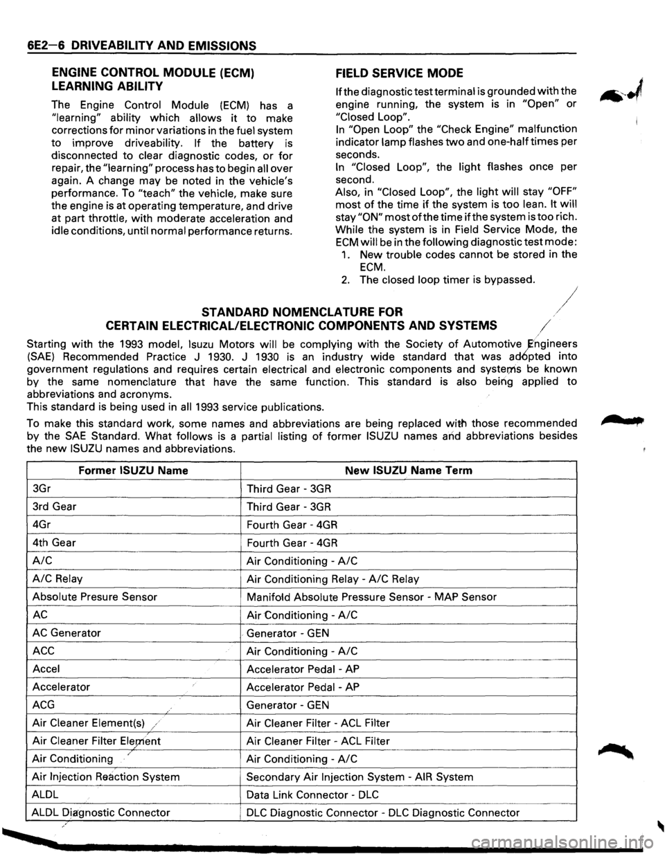
6E2-6 DRIVEABILITY AND EMISSIONS
FIELD SERVICE MODE
ENGINE
CONTROL MODULE (ECM)
LEARNING ABILITY
The Engine Control Module (ECM) has a
"learning"
ability which allows it to make
corrections
for minor variations in the fuel system
to improve driveability. If the battery is
disconnected to clear diagnostic codes, or for
repair, the "learning" process has to begin all over
again. A change
may be noted in the vehicle's
performance. To "teach" the vehicle, make sure
the engine is at operating temperature, and drive
at part throttle, with moderate acceleration and
idle conditions, until normal performance returns.
lfthe diagnostic test terminal is grounded with the
engine running, the system is in
"Open" or
"Closed Loop".
In "Open Loop" the "Check Engine" malfunction
indicator lamp flashes
two and one-halftimes per
seconds.
In "Closed Loop", the light flashes once per
second.
Also, in "Closed
Loop", the light will stay "OFF"
most of the time if the system is too lean. It will
stay"ON" mostofthetime if the system is too rich.
While the system is in Field Service Mode, the
ECM will be in the following diagnostic test mode:
1. New trouble codes cannot be stored in the
ECM.
2. The closed loop timer is bypassed.
STANDARD NOMENCLATURE FOR /
CERTAIN ELECTRICAL/ELECTRONIC COMPONENTS AND SYSTEMS /
Starting with the 1993 model, lsuzu Motors will be complying with the Society of Automotive ~ngineers
(SAE) Recommended Practice J 1930. J 1930 is an industry wide standard that was ad6pted into
government regulations and requires certain electrical and electronic components and
syster;ns be known
by the same
nomenclature that have the same function. This standard is also being applied to
abbreviations and acronyms.
This standard is being used in
all 1993 service publications.
To make this standard work, some names and abbreviations are being replaced
with those recommended
by the
SAE Standard. What follows is a partial listing of former ISUZU names and abbreviations besides
the
new ISUZU names and abbreviations.
Former ISUZU Name New ISUZU Name Term
3Gr
Third Gear -3GR
3rd Gear
Third Gear -3GR
4Gr
Fourth Gear -4GR
4th Gear
Fourth Gear -4GR
A/C Air Conditioning -A/C
A/C
Relay Air Conditioning Relay -A/C Relay
Absolute Presure Sensor
Manifofd Absolute Pressure Sensor -MAP Sensor
AC Air Conditioning -A/C
AC Generator . Generator -GEN
ACC Air Conditioning -A/C
Accel
Accelerator Pedal -AP
Accelerator
Accelerator Pedal -AP
ACG Generator -GEN
Air Cleaner Element(s) / Air Cleaner Filter -ACL Filter
Air Cleaner Filter Ele;nent Air Cleaner Filter -ACL Filter
Air Conditioning / Air Conditioning -A/C
Air Injection Reaction System Secondary Air Injection System -AIR System
ALDL Data Link Connector -
DLC
ALDL Diagnostic Connector DLC Diagnostic Connector -DLC Diagnostic Connector ,.
, ....
Page 705 of 1928
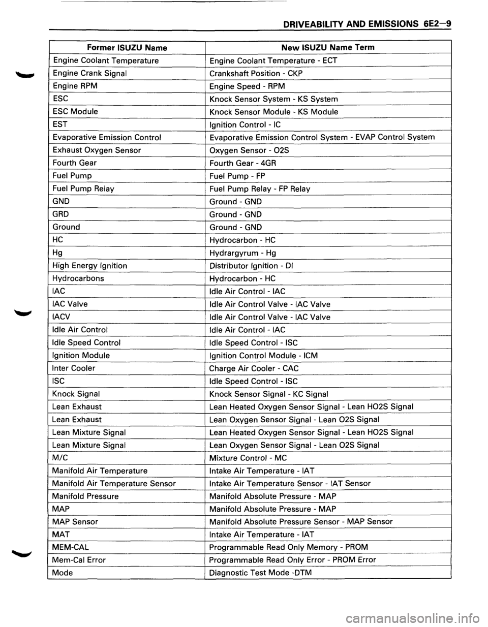
DRIVEABILITY AND EMISSIONS 6E2-9
Former ISUZU Name New ISUZU Name Term
Engine Coolant Temperature
Engine Coolant Temperature -ECT
Engine Crank Signal Crankshaft Position -CKP
Engine RPM Engine Speed -RPM
ESC Knock Sensor System-KS System
ESC Module Knock Sensor Module -KS Module
EST Ignition Control -IC
Evaporative Emission Control Evaporative Emission Control System -EVAP Control System
Exhaust Oxygen Sensor
Oxygen Sensor -
02S
Fourth Gear
Fourth Gear -4GR
Fuel Pump Fuel Pump -FP
Fuel Pump Relay
Fuel Pump Relay -FP Relay
GND Ground-GND
GAD Ground-GND
Ground Ground-GND
HC Hydrocarbon -HC
Hg Hydrargyrum-Hg
High Energy Ignition Distributor Ignition -Dl
Hydrocarbons
Hydrocarbon -HC
lAC
Idle Air Control-lAC
lAC Valve
Idle
Air Control Valve-lAC Valve
IACV Idle
Air Control Valve -lAC Valve
Idle
Air Control Idle Air Control -lAC
Idle
Speed Control Idle Speed Control -ISC
Ignition Module
Ignition Control Module -ICM
Inter Cooler Charge Air Cooler -CAC
ISC Idle Speed Control -ISC
Knock Signal Knock Sensor Signal -KC Signal
Lean Exhaust
Lean Heated Oxygen Sensor Signal -Lean H02S Signal
Lean Exhaust
Lean Oxygen Sensor Signal -Lean 02S Signal
Lean Mixture Signal Lean Heated Oxygen Sensor Signal -Lean H02S Signal
Lean Mixture Signal Lean Oxygen Sensor Signal -Lean 02S Signal
M/C Mixture Control -MC
Manifold Air Temperature Intake Air Temperature-IAT
Manifold
Air Temperature Sensor Intake Air Temperature Sensor-IAT Sensor
Manifold Pressure Manifold Absolute Pressure -MAP
MAP
Manifold Absolute Pressure -MAP
MAP Sensor
Manifold Absolute Pressure Sensor -MAP Sensor
MAT Intake Air Temperature-IAT
MEM-CAL Programmable Read Only Memory -PROM
Mem-Cal Error Programmable Read Only Error -PROM Error
Mode Diagnostic
Test Mode -DTM
Page 708 of 1928
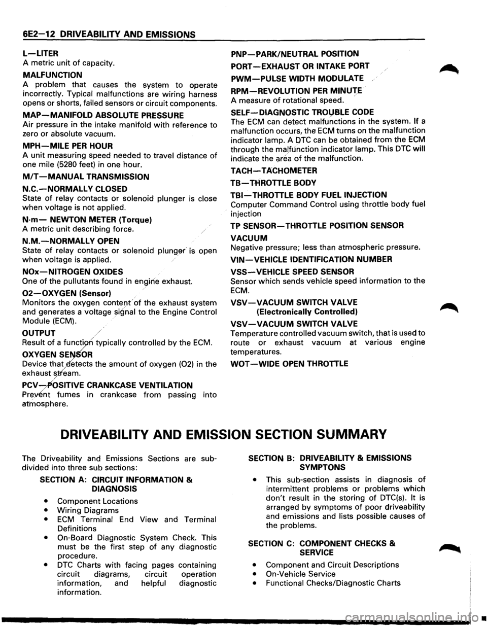
6E2-12 DRIVEABILITY AND EMISSIONS
L-LITER
A metric unit of capacity.
MALFUNCTION
A problem that causes the system to operate
incorrectly. Typical malfunctions are wiring harness
opens
or shorts, failed sensors or circuit components.
MAP-MANIFOLD ABSOLUTE PRESSURE
Air pressure in the intake manifold with reference to
zero or absolute vacuum.
MPH-MILE PER HOUR
A unit measuring speed needed to travel distance of
one mile (5280 feet) in one hour.
MIT -MANUAL TRANSMISSION
N.C.-NORMALLY CLOSED
State of relay contacts or solenoid plunger is close
when voltage is not applied.
N·m-NEWTON METER (Torque)
A metric unit describing force.
N.M.-NORMALLY OPEN
State of relay contacts or solenoid plung&r' is open
when voltage is applied.
NOx-NITROGEN OXIDES
One of the pullutants found in engirie exhaust.
02-0XYGEN (Sensor)
Monitors the oxygen contel)f of the exhaust system
and generates a
voltage signal to the Engine Control
Module (ECM).
OUTPUT
Result of a functi typically controlled by the ECM.
OXYGEN SE OR
Device that etects the amount of oxygen (02) in the
exhaust
stfeam. /
PCV-~OSITIVE CRANKCASE VENTILATION
Prey£nt fumes in crankcase from passing into
atmosphere.
PNP-PARK/NEUTRAL POSITION
PORT-EXHAUST OR INTAKE PORT
PWM-PULSE WIDTH MODULATE
RPM-REVOLUTION PER MINUTE
A measure of rotational speed.
SELF-DIAGNOSTIC TROl)SLE CODE
The ECM can detect malfunctions in the system. If a
malfunction occurs, the ECM turns on the malfunction
indicator lamp. A OTC can be obtained from the ECM
through the malfunction indicator lamp. This DTC will
indicate the area of the malfunction.
TACH-TACHOMETER
TB-THROTTLE BODY
TBI-THROTTLE BODY FUEL INJECTION
Computer Command Control using throttle body fuel
injection
TP SENSOR-THROTTLE POSITION SENSOR
VACUUM
Negative pressure; less than atmospheric pressure.
VIN-VEHICLE IDENTIFICATION NUMBER
VSS-VEHICLE SPEED SENSOR
Sensor which sends vehicle speed information to the
ECM.
VSV-VACUUM SWITCH VALVE
(Electronically Controlled)
VSV-VACUUM SWITCH VALVE
Temperature controlled vacuum switch, that is used to
route or exhaust vacuum at various engine
temperatures.
WOT -WIDE OPEN THROTTLE
DRIVEABILITV AND EMISSION SECTION SUMMARY
The Driveability and Emissions Sections are sub
divided into three sub sections:
SECTION A: CIRCUIT INFORMATION &
DIAGNOSIS
• Component Locations
• Wiring Diagrams
• ECM Terminal End View and Terminal
Definitions
• On-Board Diagnostic System Check. This
must be the first step of any diagnostic
procedure.
• DTC Charts with facing pages containing
circuit diagrams, circuit operation
information, and
helpful diagnostic
information.
SECTION B: DRIVEABILITY & EMISSIONS
SYMPTONS
• This sub-section assists in diagnosis of
intermittent problems or problems which
don't result in the storing of DTC(s). It is
arranged
by symptoms of poor driveability
and emissions and lists possible causes of
the problems.
SECTION C: COMPONENT CHECKS &
SERVICE
• Component and Circuit Descriptions
• On-Vehicle Service
• Functional
Checks/Diagnostic Charts
•
Page 711 of 1928
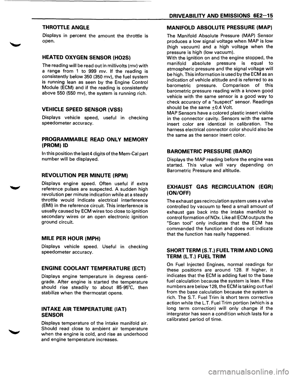
THROTTLE ANGLE
Displays in percent the amount the throttle is
open.
HEATED OXYGEN SENSOR (H02S)
The reading will be read out in millivolts (mv) with
a range from 1 to 999 mv. If the reading is
consistently
below 350 (350 mv), the fuel system
is running
lean as seen by the Engine Control
Module
(ECM) and if the reading is consistently
above
550 (550 mv), the system is running rich.
VEHICLE SPEED SENSOR (VSS)
Displays vehicle speed, useful in checking
speedometer accuracy.
PROGRAMMABLE READ ONLY MEMORY
(PROM)
ID
In this position the last4 digits of the Mem-Cal part
number will be displayed.
REVOLUTION PER MINUTE (RPM)
Displays engine speed. Often useful if extra
reference pulses are suspected. A sudden high
revolution per minute indication while at a steady
throttle
would indicate electrical interference
(EMI) in the reference circuit. This interference is
usually caused by ECM wires too close to ignition
secondary wires
or an open electronic ignition
ground circuit.
MILE PER HOUR (MPH)
Displays vehicle speed. Useful in checking
speedometer accuracy.
ENGINE COOLANT TEMPERATURE (ECT)
Displays engine temperature in degress centi
grade.
After engine is started the temperature
should rise steadily to about
85-95·c, then
stabilize
when the thermostat opens.
INTAKE AIR TEMPERATURE (IAT)
SENSOR
Displays temperature of the intake manifold air.
Should read close to ambient air temperature
when the engine is cold, and rise
as underhood
and engine temperature increases.
DRIVEABILITY AND EMISSIONS 6E2-15
MANIFOLD ABSOLUTE PRESSURE (MAP)
The Manifold Absolute Pressure (MAP) Sensor
produces a low signal voltage when MAP is low
(high vacuum) and a high voltage when the
pressure is high (low vacuum).
With the ignition on and the engine stopped, the
manifold absolute pressure is equal
to
atmospheric pressure and the signal voltage will
be high. This information is used by the ECM as an
indication of vehicle altitude and is referred to as
barometric pressure. Comparison of this
barometric pressure reading
with a known good
vehicle
with the same sensor is a good way to
check accuracy
of a "suspect" sensor. Readings
should be the same
±0.4 Volt.
MAP
Sensors have a colored plastic insert visible
in the connector cavity.
Sensors with the same
insert color are identical in calibration. The
harness electrical connector color should also be
the same
as the sensor insert color.
BAROMETRIC PRESSURE (BARO)
Displays the MAP reading before the engine was
started. This value
will vary depending on
Barometric Pressure and altitude.
EXHAUST GAS RECIRCULATION (EGR)
(ON/OFF)
The exhaust gas recirculation system uses a valve
controlled by vacuum to feed a small amount of
exhaust gas back into the intake manifold to
control formation
of NOx. Like all ECM outputs the
"Scan tool" only indicates that the ECM has
commanded the function and does
not indicate
that the function has
really happened.
SHORT TERM (S.T.) FUEL TRIM AND LONG
TERM (L.T.) FUEL TRIM
On Fuel Injected Engines, normal readings for
these positions are around 128. If higher, it
indicates that the ECM is adding fuel to the base
fuel calculation because the system is lean.
If the
numbers are below 128, the
ECM is taking out fuel
from the base calculation because the system is
rich. The
S.T. Fuel Trim is short term corrective
action while the
L.T. Fuel Trim portion (which is a
long term correction)
will only change if the
intergrator has seen a condition which lasts
for a
calibrated period
of time.
Page 712 of 1928
6E2-16 DRIVEABILITV AND EMISSIONS
LONG TERM (LT.) FUEL TRIM
There are from zero to seventeen different cells
which the Engine Control Module (ECM) learns at
depending on revolution per minute (rpm) and
manifold absolute pressure. This parameter
will
display what cell the ECM is using for the fuel
calculation at the time.
IDLE AIR CONTROL (lAC) COUNTS
This system is used to control engine idle speed to
the desired rpm, for different operating
conditions.
In this diagnostic test mode, the
numbers
will indicate what position the ECM
thinks the valve is in. The ECM moves the idle air
control in counts and these counts are displayed
on a
"Scan tool".
DESIRED REVOLUTION PER MINUTE
Indicates the rpm to which the ECM is trying to
control the idle.
AIR CONDITIONING (A/C) REQUEST
Displays the state of the Air Conditioning (A/C)
signal line to the ECM. Should read "YES"
whenever the A/C is requested.
AIR CONDITIONING {A/C) CLUTCH
Displays "ON" when the ECM has commanded
the
A/C Clutch "ON".
POWER STEERING PRESSURE (PSP)
SWITCH
Displays the state of switch. This reading may
vary
with the tool used and the type of switch
installed on the vehicle. The important thing is
that the reading changes state (switches) when
the steering is moved against the stops.
BA TTERV POSITIVE VOLTAGE
Displays the battery positive voltage detected at
the
ECM ignition input.
SPARK ADVANCE
This is a amount of total spark advance including
the base electronic ignition timing.
START UP ENGINE COOLANT
This parameter is the engine coolant temperature
at the
time the engine was started.
ENGINE SPEED (RPM)
RPM calculated during a crank mode, helpful in
diagnosing a NON-start condition.
FUEL TRIM ENABLE
This value is an indication when the Fuel Trim
Enable values are being updated within the ECM
program.
AIR/FUEL RATIO
This is the air to fuel ratio that is being
commanded to the injectors.
INDUCTION AIR CONTROL
The "Scan tool" will display the command being
given to the induction air control
plate system
solenoid.
SECTION B-DRIVEABILITY SYMPTOMS
Always start with Section "A" "On-Board Diagnostic
System Check" before proceeding to the driveability
symptoms.
Section "A" checks the ECM which may
cause the driveability problem. A definition
of each
symptom is included. This will then lead to the most
probable causes of the driveability problem.
SECTION C-COMPONENTS SYSTEMS
There are many component systems that are used to
control fuel and emissions. Section "C" introduces
each component system or control
with a general
description, diagnosis, and on-vehicle service.
Each
of the Section "C" diagnosis sections will contain
information on
how the "Scan tool" can be used for
diagnosing a particular component when a trouble
code has
not been set. (example: Section "C1" under
diagnosis
will explain how the "Scan tool" can be used
for diagnosis as well as what the normal readings
would be for the ECM Sensors.
•
Page 713 of 1928
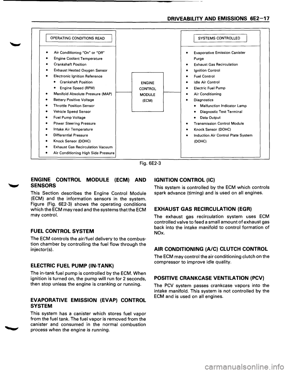
DRIVEABILITY AND EMISSIONS 6E2-17
I OPERATING CONDITIONS READ I
I SYSTEMS CONTROLLED I
• Air Conditioning "On" or "Off" • Evaporative Emission Canister
• Engine Coolant Temperature Purge
• Crankshaft Position • Exhaust Gas Recirculation
• Exhaust Heated Oxygen Sensor • Ignition Control
• Electronic Ignition Reference • Fuel Control
• Crankshaft Position
ENGINE • Idle Air Control
• Engine Speed (RPM} CONTROL • Electric Fuel Pump
• Manifold Absolute Pressure (MAP)
MODULE • Air Conditioning
• Battery Positive Voltage (ECM) • Diagnostics
• Throttle Position Sensor • Malfunction Indicator Lamp
• Vehicle Speed Sensor • Diagnostic Test Terminal
• Fuel Pump Voltage • Data Output
• Power Steering Pressure • Transmission Control Module
• Intake Air Temperature • Knock Sensor (DOHC)
• Differential Pressure • Induction Air Control Plate System
• Knock Sensor (DOHC)
(DOHC)
• Exhaust Gas Recirculation Vacuum
• Air Conditioning High Side Pressure
Fig. 6E2-3
ENGINE CONTROL MODULE (ECM) AND
SENSORS
This Section describes the Engine Control Module
(ECM) and the information sensors in the system.
Figure (Fig. 6E2-3) shows the operating conditions
which the
ECM may read and the systems thatthe ECM
may control.
FUEL CONTROL SYSTEM
The ECM controls the air/fuel delivery to the combus
tion chamber by
controlling the fuel flow through the
injector(s).
ELECTRIC FUEL PUMP (IN-TANK)
The in-tank fuel pump is controlled by the ECM. When
ignition is turned on, the
pump will run for 2 seconds,
then stop
unless the engine is cranking or running.
EVAPORATIVE EMISSION (EVAP) CONTROL
SYSTEM
This system has a canister which stores fuel vapor
from the fuel tank. The fuel vapor is removed from the
canister and consumed in the
normal combustion
process when the engine
is running.
IGNITION CONTROL (IC)
This system is controlled by the ECM which controls
spark advance (timing) and is used on all engines.
EXHAUST GAS RECIRCULATION (EGR)
The exhaust gas recirculation system uses ECM
controlled valve to feed a small amount of exhaust gas
back into the intake
manifold to control formation of
NOx.
AIR CONDITIONING (A/C) CLUTCH CONTROL
The ECM may control the air conditioning clutch on the
compressor
to improve idle quality.
POSITIVE CRANKCASE VENTILATION (PCV)
The PCV system passes crankcase vapors into the
intake
manifold. This system is not controlled by the
ECM and is used on all engines.
Page 719 of 1928
DRIVEABILITY AND EMISSIONS 6E2-23
SECTION A
ENGINE COMPONENTS/WIRING DIAGRAMS/DIAGNOSTIC
CHARTS
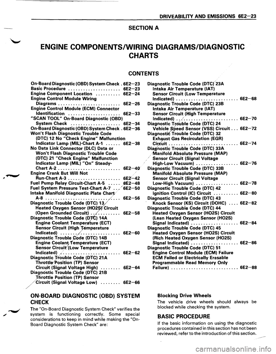
CONTENTS
On-Board Diagnostic (OBD} System Check . 6E2-23
Basic Procedure . . . . . . . . . . . . . . . . . . . . . 6E2-23
Engine Component Location . . . . . . . . . . 6E2-24
Engine Control Module Wiring
Diagrams . . . . . . . . . . . . . . . . . . . . . . . . . 6E2-26
Engine Control Module (ECM) Connector
Identification . . . . . . . . . . . . . . . . . . . . . 6E2-33
"SCAN TOOL" On-Board Diagnostic (OBD)
System Check . . . . . . . . . . . . . . . . . . . . 6E2-34
On-Board Diagnostic (OBD} System Check . 6E2-36
Won't Flash Diagnostic Trouble Code
(DTC)
12 No "Check Engine" Malfunction
Indicator Lamp (MIL)-Chart A-1 . . . . . . 6E2-38
No Data Link Connector (DLC) Data or
Won't Flash Diagnostic Trouble Code
(DTC)
21 "Check Engine" Malfunction
Indicator Lamp (MIL} "On" Steady-
Chart A-2 . . . . . . . . . . . . . . . . . . . . . . . . . 6E2-40
Engine Crank But Will Not
Run-Chart A-3 . . . . . . . . . . . . . . . . . . . . . 6E2:.....42
Fuel Pump Relay Circuit-Chart A-5 . . . . . 6E2-48
Fuel System Pressure Test-Chart A-7 ..• /6E2-50
Intake Manifold Diagnostic Plate Chart/
A-8 ......................... ,-:· . . . 6E2-56
Diagnostic Trouble Code (DTC~13 /
Heated Oxygen Sensor (H02 Circuit
(Open Grounded Circuit) . . . . . . . . . . . 6E2-58
Diagnostic Trouble Code (D'JiC) 14A
Engine Coolant Temperaiure (ECT}
Sensor Circuit (High -:remperature
Indicated) ....... /. . . . . . . . . . . . . . . . 6E2-60
Diagnostic Trouble P'ode (DTC} 14B
Engine
Coolan·vremperature (ECT)
Sensor Circuit'(Low Temperature
Indicated) ./. . . . . . . . . . . . . . . . . . . . . . . 6E2-62
Diagnostic Jtouble Code (DTC) 21A
Throtti~,.Position (TP) Sensor
Circu)t (Signal Voltage High) . . . . . . . . 6E2-64
Diag.,Ostic Trouble Code (DTC) 21B
Jflrottle Position (TP} Sensor
//Circuit (Signal Voltage Low} ........ 6E2-66
ON-BOARD DIAGNOSTIC (OBD) SYSTEM
CHECK
The "On-Board Diagnostic System Check" verifies the
system is functioning correctly.
Some special
considerations
to keep in mind while making the "On
Board Diagnostic System Check" are:
Diagnostic Trouble Code (DTC(23A
Intake Air Temperature (IAT)
Sensor Circuit (low Temperature
Indicated) ......................... 6E2-68
Diagnostic Trouble Code (DTC) 23B
Intake Air Temperature (IAT)
Sensor Circuit (High Temperature
Indicated) ... / ...................... 6E2-70
Diagnostic T[ouble Code (DTC} 24
Vehicle )!Peed Sensor (VSS} Circuit ... 6E2-72
DiagnostiC Trouble Code (DTC) 32
Exh,tist Gas Recirculation (EGR}
Cir,.Cuit ............................ 6E2-74
Dia,gnostic Trouble Code (DTC} 33A
·Manifold Absolute Pressure (MAP)
Sensor Circuit (Signal Voltage
High-Low Vacuum) ................. 6E2-76
Diagnostic Trouble Code (DTC) 33B
Manifold Absolute Pressure (MAP}
Sensor Circuit (Signal Voltage
Low-High Vacuum) ................. 6E2-78
Diagnostic Trouble Code (DTC) 42
Ignition Control (IC) Circuit . . . . . . . . . . 6E2-80
Diagnostic Trouble Code (DTC} 43
Knock Sensor (KS} Circuit (DOHC) .... 6E2-82
Diagnostic Trouble Code (DTC) 44
Heated Oxygen Sensor (H02S} Circuit
(Lean Heated Oxygen Sensor (H02S)
Signal Indicated} . . . . . . . . . . . . . . . . . . . 6E2-84
Diagnostic Trouble Code (DTC) 45
Heated Oxygen Sensor (H02S) Circuit
(Rich Heated Oxygen Sensor (H02S)
Signal Indicated) . . . . . . . . . . . . . . . . . . . 6E2-86
Diagnostic Trouble Code (DTC) 51
Engine Control Module (ECM} Failure
ECM Failed
or Electrically Erasable
Programmable Read Memory Only
Failure} ........................... 6E2-88
Blocking Drive Wheels
The vehicle drive wheels should always be
blocked
while checking the system.
BASIC PROCEDURE
If the basic information on using the diagnostic
procedures contained in this section has
not been
reviewed, refer
to the introduction of this section.
Page 720 of 1928
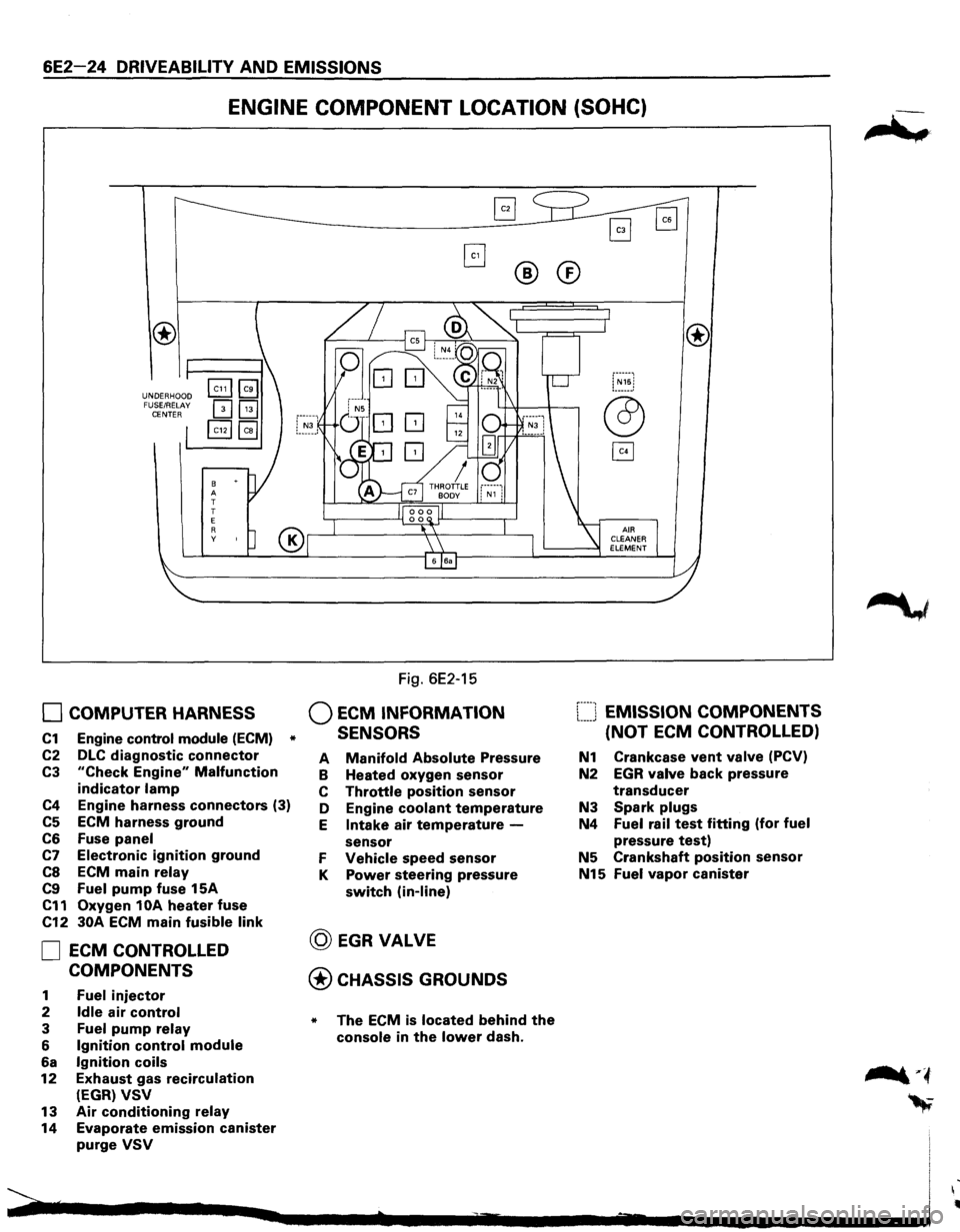
6E2-24 DRIVEABILITY AND EMISSIONS
ENGINE COMPONENT LOCATION (SOHC)
UNDERHOOD
FUSE/RELAY
CENTER
8 A
T
T
E
R y
0 COMPUTER HARNESS
C1 Engine control module (ECM) *
C2 DLC diagnostic connector
C3 "Check Engine" Malfunction
indicator lamp
C4 Engine harness connectors (3)
C5 ECM harness ground
C6 Fuse panel
C7 Electronic ignition ground
CS ECM main relay
C9 Fuel pump fuse 15A
C11 Oxygen 1 OA heater fuse
C12 30A ECM main fusible link
0 ECM CONTROLLED
COMPONENTS
1 Fuel injector
2 Idle air control
3 Fuel pump relay
6 Ignition control module
6a Ignition coils
12 Exhaust gas recirculation
(EGR) VSV
13 Air conditioning relay
14 Evaporate emission canister
purge VSV
Fig. 6E2-15
Q ECM INFORMATION
SENSORS
®
A Manifold Absolute Pressure
B Heated oxygen sensor
C Throttle position sensor
D Engine
coolant temperature
E Intake air temperature -
sensor
F Vehicle speed sensor
K Power steering pressure
switch (in-line)
@ EGRVALVE
@CHASSIS GROUNDS
* The ECM is located behind the
console in the lower dash.
®
[::::J EMISSION COMPONENTS
(NOT
ECM CONTROLLED)
N1 Crankcase vent valve (PCV)
N2 EGR valve back pressure
transducer
N3 Spark plugs
N4 Fuel rail test fitting (for fuel
pressure test)
N5 Crankshaft position sensor
N15 Fuel vapor canister
Page 721 of 1928
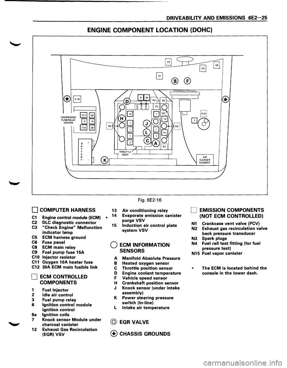
DRIVEABILITY AND EMISSIONS 6E2-25
ENGINE COMPONENT LOCATION (DOHC)
®B
UNDERHOOD FUSE/RELAY CENTER
B A T
T
E
A y
0 COMPUTER HARNESS
C1 Engine control module (ECM)
C2 DLC diagnostic connector
C3 "Check Engine" Malfunction
indicator lamp
C5 ECM harness ground
C6 Fuse panel
C8 ECM main relay
C9 Fuel pump fuse 15A
C10 Injector resistor
C11 Oxygen 1 OA heater fuse
C12
30A ECM main fusible link
0 ECM CONTROLLED
COMPONENTS
1 Fuel injector
2 Idle air control
3 Fuel pump relay
6 Ignition control module
ignition control
6a Ignition coils
7 Knock sensor Module under
charcoal canister
12
Exhaust Gas Recirculation
(EGR) VSV
*
®®
Fig. 6E2-16
13 Air conditioning relay
14 Evaporate emission canister
purge VSV
15 Induction air control plate
system VSV
Q ECM INFORMATION
SENSORS
A Manifold Absolute Pressure
B Heated oxygen sensor
c Throttle position sensor
D Engine
coolant temperature
F Vehicle speed sensor
H Crankshaft
position sensor
J Knock sensor
(under intake
assembly)
K Power steering pressure
switch (in-line)
L Intake air temperature
@ EGRVALVE
@ CHASSIS GROUNDS
f----1 EMISSION COMPONENTS !.-----' (NOT ECM CONTROLLED)
N1 Crankcase vent valve (PCV)
N2 Exhaust gas
recirculation valve
back pressure transducer
N3 Spark plugs
N4 Fuel rail test fitting (for fuel
pressure test)
N15 Fuel vapor canister
* The ECM is located behind the
console in the lower dash.