ABS ISUZU TROOPER 1995 Workshop Manual
[x] Cancel search | Manufacturer: ISUZU, Model Year: 1995, Model line: TROOPER, Model: ISUZU TROOPER 1995Pages: 1928
Page 570 of 1928
1"!
6A 1-12 ENGINE (V6 3.2L DOHC AND SOHC)
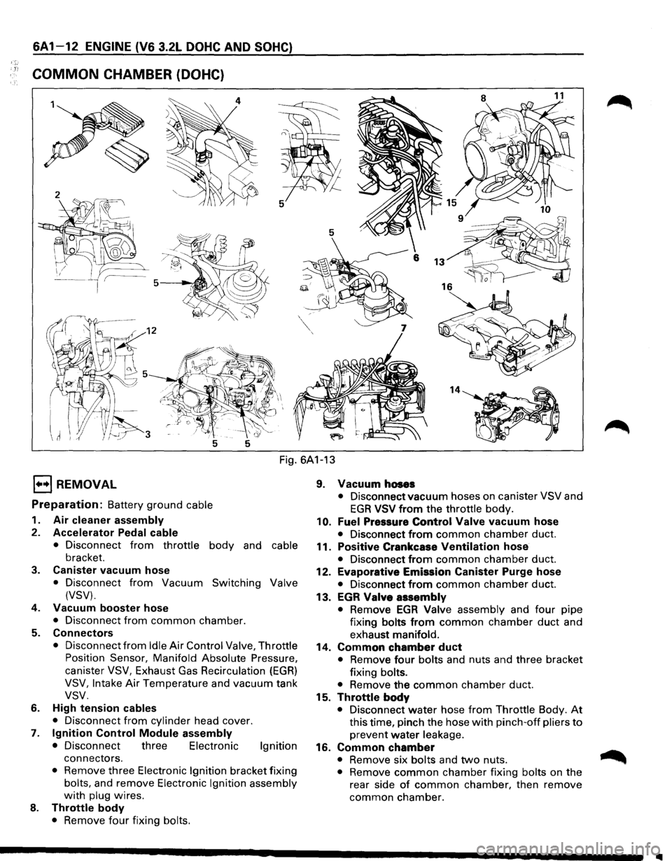
COMMON CHAMBER (DOHC)
Fig. 6A1-13
l•+l REMOVAL
Preparation: Battery ground cable
1. Air cleaner assembly
2. Accelerator Pedal cable
• Disconnect from throttle body and cable
bracket.
3. Canister vacuum hose
• Disconnect from Vacuum Switching Valve
(VSV).
4.
Vacuum booster hose
• Disconnect from common chamber.
5. Connectors
• Disconnect from Idle Air Control Valve, Throttle
Position Sensor, Manifold Absolute Pressure,
canister VSV, Exhaust Gas Recirculation (EGR)
VSV, Intake Air Temperature and vacuum tank
vsv.
6. High tension cables
•
Disconnect from cylinder head cover.
7. Ignition Control Module assembly
• Disconnect three Electronic Ignition
connectors.
• Remove three Electronic Ignition bracket fixing
bolts, and remove Electronic Ignition assembly
with plug wires.
8. Throttle body
• Remove four fixing bolts.
9. Vacuum hoses
• Disconnect vacuum hoses on canister VSV and
EGR VSV from the throttle body.
10. Fuel Pressure Control Valve vacuum hose
• Disconnect from common chamber duct.
11.
Positive Crankcase Ventilation hose
• Disconnect from common chamber duct.
12.
Evaporative Emission Canister Purge hose
• Disconnect from common chamber duct.
13.
EGR Valve assembly
• Remove EGA Valve assembly and four pipe
fixing
bolts from common chamber duct and
exhaust
manifold.
14. Common chamber duct
• Remove four bolts and nuts and three bracket
fixing
bolts.
•
Remove the common chamber duct.
15.
Throttle body
• Disconnect water hose from Throttle Body. At
this time, pinch the hose with pinch-off pliers to
prevent water leakage.
16. Common chamber
• Remove six bolts and two nuts. ~
• Remove common chamber fixing bolts on the
rear side
of common chamber, then remove
common chamber.
1111
Page 574 of 1928
.,
6A1-16 ENGINE (V6 3.2L DOHC AND SOHC}
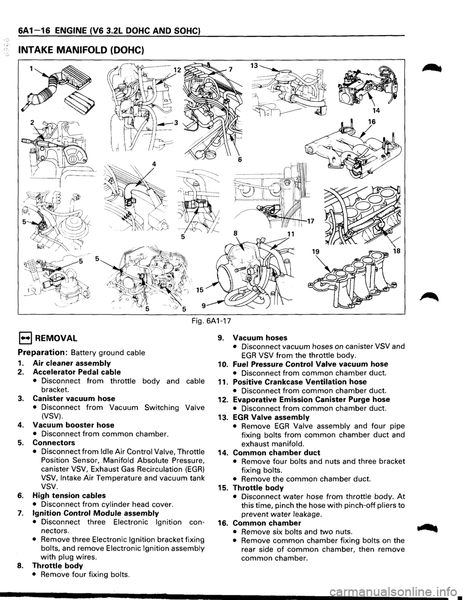
INTAKE MANIFOLD (DOHC)
Fig. 6A1-17
1••1 REMOVAL
Preparation: Battery ground cable
1. Air cleaner assembly
2. Accelerator Pedal cable
• Disconnect from throttle body and cable
bracket.
3. Canister vacuum hose
• Disconnect from Vacuum Switching Valve
(VSV).
4. Vacuum booster hose
• Disconnect from common chamber.
5. Connectors
• Disconnect from Idle Air Control Valve, Throttle
Position Sensor, Manifold Absolute Pressure,
canister
VSV, Exhaust Gas Recirculation (EGR)
VSV, Intake Air Temperature and vacuum tank
vsv.
6. High tension cables
• Disconnect from cylinder head cover.
7. Ignition Control Module assembly
• Disconnect three Electronic Ignition con
nectors.
• Remove three Electronic Ignition bracket fixing
bolts, and remove Electronic Ignition assembly
with plug wires.
8. Throttle body
• Remove four fixing bolts.
9. Vacuum hoses
• Disconnect vacuum hoses on canister VSV and
EGR VSV from the throttle body.
10. Fuel Pressure Control Valve vacuum hose
• Disconnect from common chamber duct.
11. Positive Crankcase Ventilation hose
• Disconnect from common chamber duct.
12. Evaporative Emission Canister Purge hose
• Disconnect from common chamber duct.
13. EGR Valve assembly
• Remove EGR Valve assembly and four pipe
fixing
bolts from common chamber duct and
exhaust
manifold.
14. Common chamber duct
• Remove four bolts and nuts and three bracket
fixing
bolts.
•
Remove the common chamber duct.
15. Throttle body
• Disconnect water hose from throttle body. At
this time, pinch the hose with pinch-off pliers to
prevent water leakage.
16. Common chamber
• Remove six bolts and two nuts.
• Remove common chamber fixing bolts on the
rear side
of common chamber, then remove
common chamber.
•
Page 584 of 1928
6A1-26 ENGINE (V& 3.2L DOHC AND SOHC)
1••1 REMOVAL
Preparation: Battery ground cable
1. Air cleaner assembly
2. Radiator upper fan shroud
• Remove from radiator.
3. Cooling fan assembly
• Remove four nuts, then the cooling fan
assembly.
4. Accelerator Pedal cable
• Disconnect from throttle body and cable
bracket.
5. Vacuum booster hose
• Disconnect from common chamber.
6. Connectors
• Disconnect from Manifold Absolute Pressure,
canister Vacuum Switching Valve (VSV),
Exhaust
Gas Recirculation VSV, Intake Air
Temperature and ground cable.
7. High tension cables
• Disconnect from cylinder head cover.
8. Ignition Control Module assembly
• Disconnect three Electronic Ignition con
nectors.
• Remove three Electronic Ignition bracket fixing
bolts, and remove Electronic
Ignition assembly
with high tension cables.
9. Throttle body
• Remove four fixing bolts.
10. Vacuum hoses
• Disconnect vacuum hoses on canister VSV and
Exhaust Gas Recirculation
VSV from the
throttle body.
11. Positive Crankcase Ventilation hose
• Disconnect from common chamber.
12. Fuel Pressure Control Valve vacuum hose
• Disconnect from common chamber.
13. Evaporative Emission Canister Purge hose
• Disconnect from common chamber.
14. Exhaust Gas Recirculation Valve assembly
• Remove five bolts from common chamber,
exhaust manifold and cylinder head cover.
15. Common chamber
• Remove six bolts, two nuts and three bracket
fixing bolts, then remove the
common
chamber.
16. Fuelhoses
• Disconnect feed and return fuel hoses from fuel
pipes, and remove
two bracket fixing bolts on
the cylinder head cover.
17. Power steering pump drive belt
18. Air Conditioning compressor drive belt
19. Generator drive belt
20. Power steering pump
21. Fan pulley assembly
22. Crankshaft pulley assembly
lf5\l • Using special tool J-8614-01, hold crankshaft
t:::!il pulley.
•
Remove center bolt, then the pulley.
23. Oil cooler hose
• Remove two cooler hose bracket fixing bolts on
the timing belt cover.
24. Timing belt cover
25. Pusher
CAUTION:
The pusher prevents air from entering the oil chamber.
Its rod must always be facing upward.
26. Timing belt
CAUTIONS:
1) Do not bend or twist the belt, otherwise its core
could
be damaged. The belt should not be bent at
a radius less than 30mm.
2) Do not allow oil or other chemical substances to
come in contact with the belt. They will shorten
the belt life.
3) Do not attempt to pry or stretch the belt with a
screwdriver
or any other tool during installation.
4) Store timing belt in a cool and dark place. Never
expose the belt
to direct sunlight or heat.
27. Cylinder head cover
• Remove 11 fixing bolts, then the cylinder head
cover.
28. Camshaft
• Camshaft pulley fixing bolt and camshaft pulley
•
Front plate fixing bolts and front plate
• Camshaft bracket fixing bolts and camshaft
29. Rocker arm
• Fixing bolts and rocker arm
I••! INSTALLATION
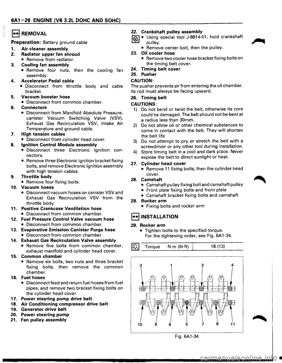
29. Rocker arm
• Tighten bolts to the specified torque.
For the tightening order, see Fig. 6A 1-34.
~~~ Torque N·m (lb·ft) 18 (13)
Fig. 6A1-34
•
Page 588 of 1928
6A1-30 ENGINE (V& 3.2L DOHC AND SOHC)
· ;~; E) REMOVAL
Preparation: Battery ground cable
1. Air cleaner assembly
2. Radiator upper fan shroud
• Remove from radiator.
3. Cooling fan assembly
• Remove four nuts, then the cooling fan
assembly.
4. Accelerator Pedal cable
• Disconnect from throttle body and cable
bracket.
5. Canister vacuum hose
• Disconnect from vacuum pipe.
6. Air vacuum hose
• Disconnect from common chamber.
7. Connectors
• Disconnect from Manifold Absolute, Canister
Vacuum Switching Valve
(VSV), Exhaust Gas
Recirculation
VSV, Intake Air Temperature and
ground cable.
8. High tension cables
• Disconnect from cylinder head cover.
9. Ignition Control Module assembly
• Disconnect three Electronic Ignition
connectors.
• Remove three Electronic Ignition bracket fixing
bolts, and remove Electronic
Ignition assembly
with high tension cables.
10. Throttle body
• Remove four fixing bolts.
11. Vacuum hoses
• Disconnect vacuum hoses on canisterVSVand
Exhaust
Gas Recirculation VSV from the
throttle body.
12. Positive Crankcase Ventilation hose
• Disconnect from common chamber.
13. Fuel Pressure Control Valve vacuum hose
• Disconnect from common chamber.
14. Evaporative Emission Canister Purge hose
• Disconnect from common chamber.
15. Exhaust Gas Recirculation Valve assembly
• Remove five bolts from common chamber,
exhaust manifold and cylinder head cover.
16. Common chamber duct
• Remove four bolts, four nuts and three bracket
fixing bolts, then remove the
common
chamber duct.
• Disconnect ground cable from rear side of
common chamber.
17. Common chamber
• Remove six bolts, two nuts and three bracket
fixing bolts, then remove the
common
chamber.
18. Fuel hoses
• Disconnect feed and return fuel hoses from fuel
pipes, and remove two bracket fixing bolts on
the cylinder head cover.
19. Power steering pump drive belt
20. Air Conditioning compressor drive belt
21. Generator drive belt
22. Power steering pump
23. Fan pulley assembly
24.
Crankshaft pulley assembly
1i0iJ • Using special tool J-8614-01, hold crankshaft
~ pulley.
•
Remove center bolt, then the pulley.
25. Oil cooler hose
• Remove two cooler hose bracket fixing bolts on
the timing belt cover.
26. Timing belt cover
27. Pusher
\fl CAUTION:
Yl The pusher prevents air from entering the oil
chamber.
Its rod must always be facing upward.
28. Timing belt
\fl CAUTIONS:
Yl 1) Do not bend or twist the belt, otherwise its
core could be damaged. The belt should
not
be bent at a radius less than 30mm.
2) Do not allow oil or other chemical substances
to come in contact
with the belt. They will
shorten the belt life.
3) Do not attempt to pry or stretch the belt with a
screwdriver
or any other tool during
installation.
4) Store timing belt in a cool and dark place.
Never expose the
belt to direct sunlight or
heat.
29. Cylinder head cover
• Remove 11 fixing bolts, then the cylinder head
cover.
30. Camshaft
• Camshaft pulley fixing bolt and camshaft pulley
•
Front plate fixing bolts and front plate
• Camshaft bracket fixing bolts and camshaft
31. Swing arm
• After removing the swing arm, attach a tag
showing the place
for swing arm.
32. Hydraulic lash adjuster (HLA)
• After removing the HLA, attach a tag showing
the place
for HLA.
\fl CAUTIONS:
Yl 1) Protect precision HLA from dust and foreign
materials.
2) Do not disassemble the HLA.
3) To clean the HLA, use a clean diesel oil.
•
Page 592 of 1928
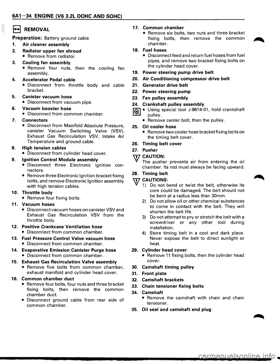
6A1-34 ENGINE (V6 3.2L DOHC AND SOHC)
1••1 REMOVAL
Preparation:
Battery ground cable
1. Air cleaner assembly
2. Radiator upper fan shroud
• Remove from radiator.
3. Cooling fan assembly
• Remove four nuts, then the cooling fan
assembly.
4. Accelerator Pedal cable
• Disconnect from throttle body and cable
bracket.
5. Canister vacuum hose
• Disconnect from vacuum pipe.
6. Vacuum booster hose
• Disconnect from common chamber.
7. Connectors
• Disconnect from Manifold Absolute Pressure,
canister Vacuum Switching Valve (VSV),
Exhaust Gas Recirculation VSV, Intake Air
Temperature and ground cable.
8. High tension cables
• Disconnect from cylinder head cover.
9. Ignition Control Module assembly
• Disconnect three Electronic Ignition con
nectors.
• Remove three Electronic Ignition bracket fixing
bolts, and remove Electronic Ignition assembly
with high tension cables.
10. Throttle body
• Remove four fixing bolts.
11. Vacuum hoses
• Disconnect vacuum hoses on canister VSV and
Exhaust Gas Recirculation
VSV from the
throttle body.
12. Positive Crankcase Ventilation hose
• Disconnect from common chamber.
13. Fuel Pressure Control Valve vacuum hose
• Disconnect from common chamber.
14. Evaporative Emission Canister Purge hose
• Disconnect from common chamber.
15. Exhaust Gas Recirculation Valve assembly
• Remove five bolts from common chamber,
exhaust manifold and cylinder head cover.
16. Common chamber duct
• Remove four bolts, four nuts and three bracket
fixing
bolts, then remove the common
chamber duct.
• Disconnect ground cable from rear side of
common chamber.
17. Common chamber
• Remove six bolts, two nuts and three bracket
fixing
bolts, then remove the common
chamber.
18. Fuel hoses
• Disconnect feed and return fuel hoses from fuel
pipes, and remove two bracket fixing bolts on
the cylinder head cover.
19. Power steering pump drive belt
20.
Air Conditioning compressor drive belt
21. Generator drive belt
22. Power steering pump
23.
Fan pulley assembly
24. Crankshaft pulley assembly
liQil • Using special tool J-8614-01, hold crankshaft
~ pulley.
• Remove center bolt, then the pulley.
25. Oil cooler hose
• Remove two cooler hose bracket fixing bolts on
the
timing belt cover.
26. Timing belt cover
27. Pusher
\fl CAUTION:
'V The pusher prevents air from entering the oil
chamber. Its rod must always be facing upward.
28. Timing belt
\fl CAUTIONS:
'V 1) Do not bend or twist the belt, otherwise its
core could be damaged. The
belt should not
be bent at a radius less than 30mm.
2) Do not allow oil or other chemical substances
to come in contact with the belt. They will
shorten the belt life.
3) Do not attempt to pry or stretch the belt with a
screwdriver or any other tool during
installation.
4) Store timing belt in a cool and dark place.
Never expose the
belt to direct sunlight or
heat.
29. Cylinder head cover
• Remove 11 fixing bolts, then the cylinder head
cover.
30. Camshaft timing pulley
31. Front plate
32. Camshaft brackets
33. Chain tensioner fixing
bolts
34. Camshaft
• Remove the camshaft with chain and chain
tensioner.
35. Oil seal and camshaft end plug
II
Page 597 of 1928
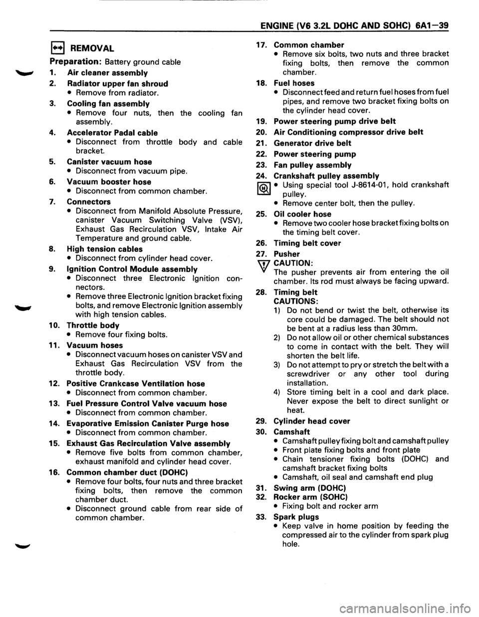
E) REMOVAL
Preparation: Battery ground cable
1. Air cleaner assembly
2. Radiator upper fan shroud
• Remove from radiator.
3. Cooling fan assembly
• Remove four nuts, then the cooling fan
assembly.
4. Accelerator Padal cable
• Disconnect from throttle body and cable
bracket.
5. Canister vacuum hose
• Disconnect from vacuum pipe.
6. Vacuum booster hose
• Disconnect from common chamber.
7. Connectors
• Disconnect from Manifold Absolute Pressure,
canister Vacuum
Switching Valve (VSV),
Exhaust Gas Recirculation VSV, Intake Air
Temperature and ground cable.
8. High tension cables
• Disconnect from cylinder head cover.
9.
Ignition Control Module assembly
• Disconnect three Electronic Ignition con
nectors.
• Remove three Electronic Ignition bracket fixing
bolts, and remove Electronic Ignition assembly
with high tension cables.
10.
Throttle body
• Remove four fixing bolts.
11. Vacuum hoses
• Disconnect vacuum hoses on canister VSV and
Exhaust Gas Recirculation
VSV from the
throttle body.
12.
Positive Crankcase Ventilation hose
• Disconnect from common chamber.
13.
Fuel Pressure Control Valve vacuum hose
• Disconnect from common chamber.
14.
Evaporative Emission Canister Purge hose
• Disconnect from common chamber.
15.
Exhaust Gas Recirculation Valve assembly
• Remove five bolts from common chamber,
exhaust
manifold and cylinder head cover.
16.
Common chamber duct (DOHC)
• Remove four bolts, four nuts and three bracket
fixing
bolts, then remove the common
chamber duct.
• Disconnect ground cable from rear side of
common chamber.
ENGINE (V6 3.2L DOHC AND SOHC) 6A1-39
17. Common chamber
• Remove six bolts, two nuts and three bracket
fixing
bolts, then remove the common
chamber.
18.
Fuelhoses
• Disconnect feed and return fuel hoses from fuel
pipes, and remove two bracket fixing bolts on
the
cylinder head cover.
19.
Power steering pump drive belt
20. Air Conditioning compressor drive belt
21. Generator drive belt
22. Power steering pump
23. Fan pulley assembly
24. Crankshaft pulley assembly
~ • Using special tool J-8614-01, hold crankshaft
~ pulley.
•
Remove center bolt, then the pulley.
25. Oil cooler hose
• Remove two cooler hose bracket fixing bolts on
the timing
belt cover.
26.
Timing belt cover
27. Pusher
\fl CAUTION:
'if The pusher prevents air from entering the oil
chamber. Its rod must always be facing upward.
28.
Timing belt
CAUTIONS:
1) Do not bend or twist the belt, otherwise its
core
could be damaged. The belt should not
be bent at a radius less than 30mm.
2) Do not allow oil or other chemical substances
to come in contact
with the belt. They will
shorten the belt life.
3) Do not attempt to pry or stretch the belt with a
screwdriver
or any other tool during
installation.
4) Store timing belt in a cool and dark place.
Never expose the belt to direct sunlight or
heat.
29.
Cylinder head cover
30. Camshaft
• Camshaft pulley fixing bolt and camshaft pulley
•
Front plate fixing bolts and front plate
• Chain
tensioner fixing bolts (DOHC) and
camshaft bracket fixing
bolts
•
Camshaft, oil seal and camshaft end plug
31. Swing arm (DOHC)
32. Rocker
arm (SOHC)
•
Fixing bolt and rocker arm
33.
Spark plugs
• Keep valve in home position by feeding the
compressed air to the
cylinder from spark plug
hole.
Page 601 of 1928
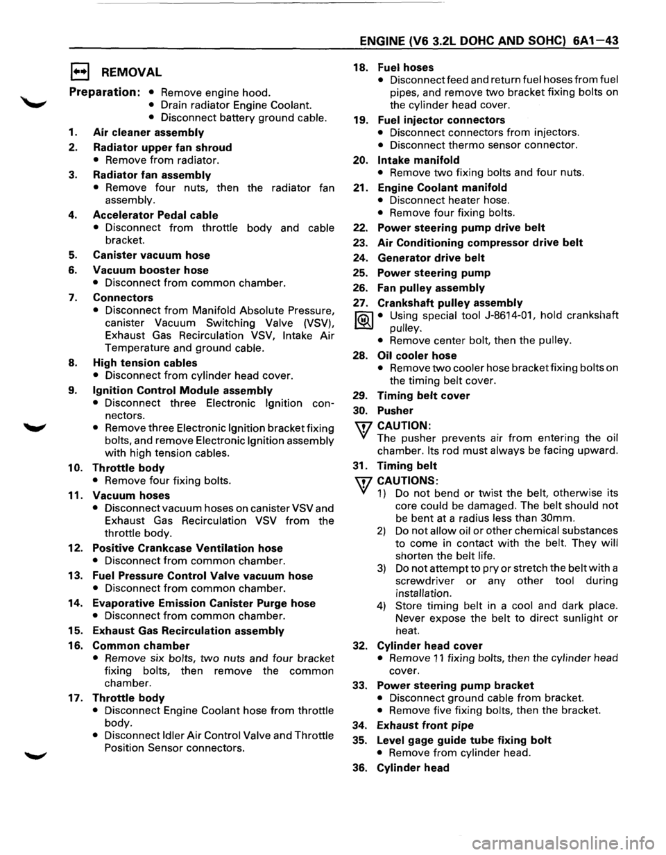
EJ REMOVAL
Preparation: • Remove engine hood.
• Drain radiator Engine Coolant.
• Disconnect battery ground cable.
1. Air cleaner assembly
2. Radiator upper fan shroud
• Remove from radiator.
3. Radiator fan assembly
• Remove four nuts, then the radiator fan
assembly.
4. Accelerator Pedal cable
• Disconnect from throttle body and cable
bracket.
5. Canister vacuum hose
6. Vacuum booster hose
• Disconnect from common chamber.
7. Connectors
• Disconnect from Manifold Absolute Pressure,
canister Vacuum Switching
Valve (VSV),
Exhaust Gas Recirculation VSV,
Intake Air
Temperature and ground cable.
8. High tension cables
• Disconnect from cylinder head cover.
9. Ignition Control Module assembly
• Disconnect three Electronic Ignition con
nectors.
• Remove three Electronic Ignition bracket fixing
bolts, and remove Electronic Ignition assembly
with high tension cables.
10. Throttle body
• Remove four fixing bolts.
11. Vacuum hoses
• Disconnect vacuum hoses on canister VSV and
Exhaust Gas Recirculation VSV
from the
throttle body.
12. Positive Crankcase Ventilation hose
• Disconnect from common chamber.
13. Fuel Pressure Control Valve vacuum hose
• Disconnect from common chamber.
14. Evaporative Emission Canister Purge hose
• Disconnect from common chamber.
15. Exhaust Gas Recirculation assembly
16. Common chamber
• Remove six bolts, two nuts and four bracket
fixing bolts, then remove the
common
chamber.
17. Throttle body
• Disconnect Engine Coolant hose from throttle
body.
• Disconnect Idler Air Control Valve and Throttle
Position Sensor connectors.
ENGINE (V6 3.2L DOHC AND SOHC) 6A1-43
18. Fuelhoses
• Disconnect feed and return fuel hoses from fuel
pipes, and remove two bracket fixing bolts on
the cylinder head cover.
19. Fuel injector connectors
• Disconnect connectors from injectors.
• Disconnect thermo sensor connector.
20. Intake manifold
• Remove two fixing bolts and four nuts.
21. Engine Coolant manifold
• Disconnect heater hose.
• Remove four fixing bolts.
22. Power steering pump drive belt
23. Air Conditioning compressor drive belt
24. Generator drive belt
25. Power steering pump
26.
Fan pulley assembly
27. Crankshaft pulley assembly
~ • Using special tool J-8614-01, hold crankshaft
~ pulley.
•
Remove center bolt, then the pulley.
28. Oil cooler hose
• Remove two cooler hose bracket fixing bolts on
the timing
belt cover.
29. Timing belt cover
30. Pusher
\fl CAUTION:
VI The pusher prevents air from entering the oil
chamber. Its rod must always be facing upward.
31. Timing belt
\fl CAUTIONS:
VI 1) Do not bend or twist the belt, otherwise its
core
could be damaged. The belt should not
be bent at a radius less than 30mm.
2) Do not allow oil or other chemical substances
to come in contact with the belt. They will
shorten the belt life.
3) Do not attempt to pry or stretch the belt with a
screwdriver
or any other tool during
installation.
4) Store timing belt in a cool and dark place.
Never expose the
belt to direct sunlight or
heat.
32. Cylinder head cover
• Remove 11 fixing bolts, then the cylinder head
cover.
33. Power steering pump bracket
• Disconnect ground cable from bracket.
• Remove five fixing bolts, then the bracket.
34. Exhaust front pipe
35.
Level gage guide tube fixing bolt
• Remove from cylinder head.
36. Cylinder head
Page 605 of 1928
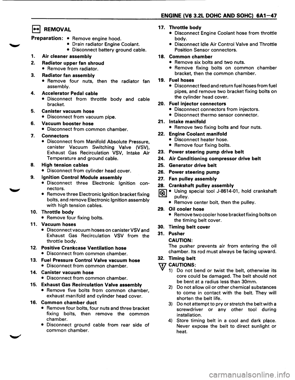
1••1 REMOVAL
Preparation: • Remove engine hood.
• Drain radiator Engine Coolant.
•
Disconnect battery ground cable.
1.
Air cleaner assembly
2. Radiator upper fan shroud
• Remove from radiator.
3. Radiator fan assembly
• Remove four nuts, then the radiator fan
assembly.
4. Accelerator Pedal cable
• Disconnect from throttle body and cable
bracket.
5. Canister vacuum hose
• Disconnect from vacuum pipe.
6.
Vacuum booster hose
• Disconnect from common chamber.
7. Connectors
• Disconnect from Manifold Absolute Pressure,
canister Vacuum Switching Valve (VSV),
Exhaust
Gas Recirculation VSV, Intake Air
Temperature and ground cable.
8. High tension cables
• Disconnect from cylinder head cover.
9. Ignition Control Module assembly
• Disconnect three Electronic Ignition con
nectors.
• Remove three Electronic Ignition bracket fixing
bolts, and remove Electronic
Ignition assembly
with high tension cables.
10. Throttle body
• Remove four fixing bolts.
11.
Vacuum hoses
• Disconnect vacuum hoses on canister VSV and
Exhaust
Gas Recirculation VSV from the
throttle body.
12.
Positive Crankcase Ventilation hose
• Disconnect from common chamber.
13. Fuel Pressure
Control Valve vacuum hose
• Disconnect from common chamber.
14.
Canister vacuum hose
• Disconnect from common chamber.
15.
Exhaust Gas Recirculation Valve assembly
• Remove five bolts from common chamber,
exhaust manifold and cylinder head cover.
16.
Common chamber duct
• Remove four bolts, four nuts and three bracket
fixing bolts, then remove the
common
chamber.
• Disconnect ground cable from rear side of
common chamber.
ENGINE (V6 3.2L DOHC AND SOHC) 6A1 47
17. Throttle body
• Disconnect Engine Coolant hose from throttle
body.
• Disconnect Idle Air Control Valve and Throttle
Position Sensor connectors.
18.
Common chamber
• Remove six bolts and two nuts.
• Remove fixing bolts on common chamber
bracket, then the
common chamber.
19.
Fuelhoses
• Disconnect feed and return fuel hoses from fuel
pipes, and remove
two bracket fixing bolts on
the cylinder head cover.
20. Fuel injector connectors
• Disconnect connectors from injectors.
• Disconnect thermo sensor connector.
21.
Intake manifold
• Remove two fixing bolts and four nuts.
22. Engine
Coolant manifold
• Disconnect heater hose.
• Remove four fixing bolts.
23.
Power steering pump drive belt
24. Air Conditioning compressor drive belt
25. Generator drive belt
26. Power steering pump
27. Fan pulley assembly
28. Crankshaft pulley assembly
I®J • Using special tool J-8614-01, hold crankshaft
pulley.
•
Remove center bolt, then the pulley.
29. Oil cooler hose
• Remove two cooler hose bracket fixing bolts on
the timing belt cover.
30. Timing belt cover
31. Pusher
CAUTION:
The pusher prevents air from entering the oil
chamber. Its rod must always be facing upward.
32.
Timing belt
w CAUTIONS:
' 1) Do not bend or twist the belt, otherwise its
core could
be damaged. The belt should not
be bent at a radius less than 30mm.
2) Do not allow oil or other chemical substances
to come in contact
with the belt. They will
shorten the belt life.
3) Do not attempt to pry or stretch the belt with a
screwdriver
or any other tool during
installation.
4) Store timing belt in a cool and dark place.
Never expose the belt to direct sunlight
or
heat.
Page 644 of 1928
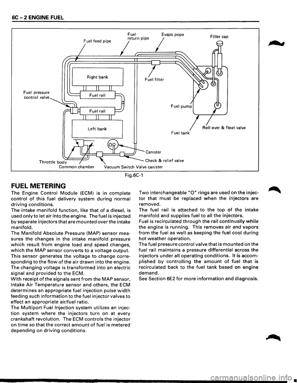
6C - 2 ENGINE FUEL
Fuel
Fuel
feed pipe return pipe Evapo pope
Fuel pressure
control valve Right
bank
Left bank Fuel tank
Canister
Throttle body Common chamber
Check & relief
valve
Vacuum Switch Valve canister
Fig.6C-1
FUEL METERING
The Engine Control Module (ECM) 1s 1n complete
control of this fuel delivery system during normal
driving conditions.
The intake manifold function, like that of a diesel, is
used
only to let air into the engine. The fuel is injected
by separate injectors that are mounted over the intake
manifold.
The Manifold Absolute Pressure (MAP) sensor mea
sures
the changes in the intake manifold pressure
which result from engine load and speed changes,
which the MAP sensor converts to a voltage output.
This sensor generates the voltage to change corre
sponding to the flow ofthe air drawn into the engine.
The
changing voltage is transformed into an electric
signal and provided to the ECM.
With receipt of the signals sent from the MAP sensor,
Intake Air Temperature sensor and others, the ECM
determines an appropriate fuel injection pulse width
feeding such information to the fuel injector valves to
effect an appropriate air/fuel ratio.
The
Multipart Fuel Injection system utilizes an injec
tion system where the injectors turn on at every
crankshaft revolution. The ECM controls the injector
on time so that the correct amount of fuel is metered
depending on driving conditions.
Two interchangeable "0" rings are used on the injec
tor that must be replaced when the injectors are
removed.
The fuel rail is attached to the top of the intake
manifold and supplies fuel to all the injectors.
Fuel is recirculated
through the rail continually while
the engine is running. This removes air and vapors
from the fuel as well as keeping the fuel cool during
hot weather operation.
The fuel pressure control valve that is mounted on the
fuel rail maintains a pressure differential across the
injectors under all operating conditions. It is accom
plished by controlling the amount of fuel that is
recirculated back
to the fuel tank based on engine
demand.
See Section 6E2 for more information and diagnosis.
;au
•
Page 689 of 1928
IGNITION SYSTEM 6D4 - 1
SECTION 604
IGNITION SYSTEM
CONTENTS
General Description ...................... .
Diagnosis
................................... .
On-Vehicle Service ....................... .
Spark Plug Wire ....................... .
Spark Plug .............................. . 6D4-1
6D4-2 6D4-3
6D4-3
6D4-3
Electronic Ignition (EI) Assembly ...
Crankshaft Position Sensor
(CKP sensor) ........................ .
Torque Specifications
................ .
Main Data and Specifications
......... . 6D4-5
6D4-5
6D4-6
6D4-7
GENERAL DESCRIPTION
Ignition is done by the Electronic Ignition (EI) that
fires directly the ignition plugs from ignition coils
through spark plug wires without using a distributor.
A pair of ignition coils for the cylinders having differ
ent phases by 360° (No.1 and No.4, No.2 and No.5,
No.3 and No.6) are
fired simultaneously.
Since the cylinder on exhaust stoke requires less
energy to fire its ignition plug, energy from the
ignition coils can be utilized to fire the mating cylin
der on compression stroke. After additional 360°
rotation, respective cylinder stokes are reversed.
TheEl consists of three ignition coils, ignition control
module, crank angle sensor, Engine Control Module
(ECM) and other components.
Module is provided under the ignition coil, connected
with ECM by means of 6-pin connector. The
ignition control module turns on/off the primary
circuit of ignition coils, and also it controls the igni
tion timing at the engine
speed below 538 rpm.
A notch in
the timing disc on the crankshaft activates
the crank angle sensor which then sends information
such as firing order and starting timing of each
ignition coil to the ECM.
Further, the El employs Ignition Control (I C) to control
similar to a distributor system.
By receiving
signals such as crank position, engine
speed, water temperature and Manifold Absolute
Pressure (MAP), the ECM controls the ignition timing.