key ISUZU TROOPER 1995 Workshop Manual
[x] Cancel search | Manufacturer: ISUZU, Model Year: 1995, Model line: TROOPER, Model: ISUZU TROOPER 1995Pages: 1928
Page 1336 of 1928
8 -146 CHASSIS ELECTRICAL
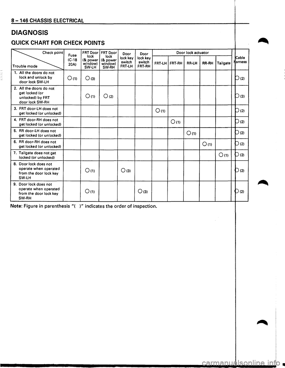
DIAGNOSIS
QUICK CHART FOR CHECK POINTS ~
~
Fuse FRT Door FRT Door
Door Door Door
lock actuator
lock lock
lock key lock key
Cable IC-18 I& power I& power 20AI window)
window) switch switch FRT-LH FRT-RH RR-LH RR-RH Tailgate
arness
T SW-LH SW-RH FRT-LH FRT-RH
1. All the doors do not
lock and unlock by
door lock SW-LH 0(1) 0131
P121
2. All the doors do not
get locked (or
0(1) 0121 Pl31 unlocked) by FRT door lock SW-RH
3. FRT door-LH does not 0(1) P121 get locked {or unlocked)
4. FRT door-RH does not 0111 P121 get
locked (or unlocked)
5. RR door-LH does not 0(1) P121 get locked (or unlocked)
6. RR door-RH does not 0111 P121 get
locked (or unlocked)
7. Tailgate does
not get 0111 P121 locked (or unlocked)
8. Door lock does not
operate when operated 0111 0131 p(2) from the door lock key SW-LH
9. Door lock does not ~ operate when operated Om 0131 P121 from the door lock key SW-RH
Note: Figure in parenthesis "( )" indicates the order of inspection.
~
•
Page 1339 of 1928
CHASSIS ELECTRICAL 8 -149
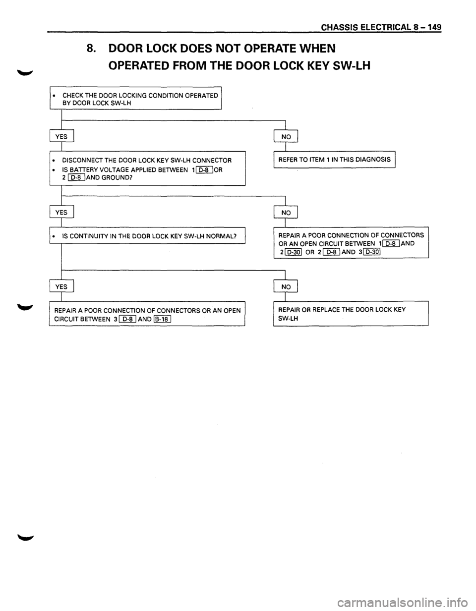
8. DOOR LOCK DOES NOT OPERATE WHEN
OPERATED FROM THE DOOR LOCK KEY SW-LH
• CHECK THE DOOR LOCKING CONDITION OPERATED
BY DOOR LOCK SW-LH
l
YES I NO l
1
• DISCONNECT THE DOOR LOCK KEY SW-LH CONNECTOR REFER TO ITEM 1 IN THIS DIAGNOSIS l
• IS BATTERY VOLTAGE APPLIED BETWEEN 1 I D-8 lOR
2 [Q]JAND GROUND?
I
YES I NO I
I
• IS CONTINUITY IN THE DOOR LOCK KEY SW-LH NORMAL? REPAIR A POOR CONNECTION OF CONNECTORS
OR AN OPEN CIRCUIT BETWEEN 1~AND
2ID-30I OR 2[@AND 3ID-30I
I
YES I NO l
I
REPAIR A POOR CONNECTION OF CONNECTORS OR AN OPEN REPAIR OR REPLACE THE DOOR LOCK KEY
CIRCUIT BETWEEN 3 [];[]AND IB-18 I SW-LH
Page 1340 of 1928
8 -150 CHASSIS ELECTRICAL
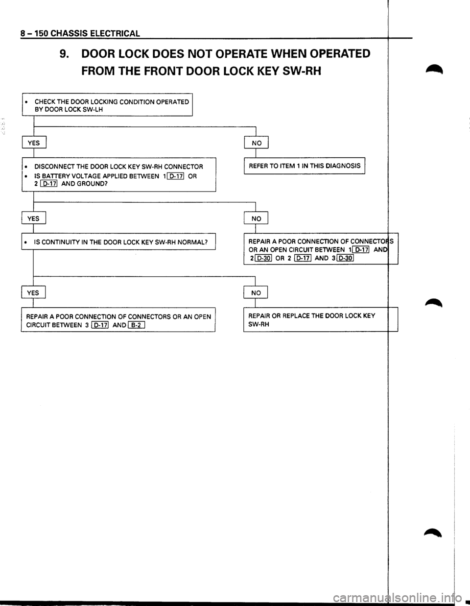
9. DOOR LOCK DOES NOT OPERATE WHEN OPERATED
FROM THE FRONT DOOR LOCK KEY SW-RH
• CHECK THE DOOR LOCKING CONDITION OPERATED BY DOOR LOCK SW-LH
YES I
• DISCONNECT THE DOOR LOCK KEY SW-RH CONNECTOR
• ISBATTERYVOLTAGEAPPLIEDBETWEEN 1ID-171 OR 21 D-171 AND GROUND?
YES I
• IS CONTINUITY IN THE DOOR LOCK KEY SW-RH NORMAL?
YES I
REPAIR A POOR CONNECTION OF CONNECTORS OR AN OPEN
CIRCUIT BETWEEN 31 D-171 AND(]]]
I
NO I
I
REFER TO ITEM 1 IN THIS DIAGNOSIS l
I
NO I
I
REPAIR A POOR CONNECTION OF CONNECTO S
OR AN OPEN CIRCUIT BETWEEN 11 D-171 ANC
2ID-30I OR 2ID-17I AND 3ID-30I
I
NO I
I
REPAIR OR REPLACE THE DOOR LOCK KEY
SW-RH
•
Page 1341 of 1928
![ISUZU TROOPER 1995 Workshop Manual (b!] INSPECTION OF THE DOOR LOCK
t!l CIRCUIT
~ Check the voltage and the continuity between
the
front door lock (& power window) switch
harness side connector terminals. (Fig. 8-185)
[E)
,](/img/61/57183/w960_57183-1340.png "ISUZU TROOPER 1995 Workshop Manual (b!] INSPECTION OF THE DOOR LOCK
t!l CIRCUIT
~ Check the voltage and the continuity between
the
front door lock (& power window) switch
harness side connector terminals. (Fig. 8-185)
[E)
,")
(b!] INSPECTION OF THE DOOR LOCK
t!l CIRCUIT
~ Check the voltage and the continuity between
the
front door lock (& power window) switch
harness side connector terminals. (Fig. 8-185)
[E)
,, r=1 ,
f.~B
~ slal7lal911o D
TerConnec- minal tor No. Wire
Item to Connecting
color Connected to be
checked terminal
No.
1
7
8
D-5
B
LIB
Ground
Power window
relay
LG/B Lock actuator
(Unlock)
Continuity 1-Ground
Voltage 7-Ground
8-9
CHASSIS ELECTRICAL8 -151
Checking conditions Standard
Continuity
Starter SW
"ON" Approx. 12V
Continuity
9 LG
(There is Continuity 1------.,..--+----------t e
Lock actuator 9-8 -som (Lock) resistance)
10 LG/W Fuse C-18
Voltage 10-Ground Approx.12V
1
(20A)
LG/L Door lock
SW-RH
(Unlock) 1-Ground
Door
lqck SW Unlock Continuity
Lock
No continuity
2 LG/R Door lock 2-Ground Door lock
SW-RH
or
door lock key
SW-LH & RH
Lock Continuity
D-30
3
SW-RH (Lock)
Door lock key
Continuity
SW-LH
& RH
(Lock)
L/Y Door lock key
SW-LH & RH
(Unlock) Unlock
No continuity
3-Ground
Door lock Unlock Continuity
key
SW-LH &
RH Lock No continuity
Fig 8-185
FRONT DOOR LOCK (& POWER
WINDOW) SWITCH-LH
The front door lock (&power window) switch sends
out to each door lock actuator the lock/unlock signals
received
from both door lock switch and door lock
key switch.
Fig 8-186
Page 1343 of 1928
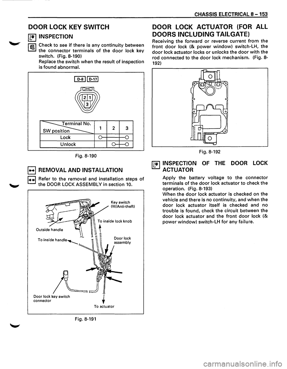
DOOR LOCK KEY SWITCH
~ INSPECTION
l'fiil Check to see if there is any continuity between
~ the connector terminals of the door lock key
switch. (Fig.
8-190)
Replace the switch when the result of inspection
is found abnormal.
~lo-nl
•
~ s 1 2 3
Lock 0 0
Unlock o--o
Fig. 8-190
E) REMOVAL AND INSTALLATION
1••1 Refer to the removal and installation steps of
the DOOR LOCK ASSEMBLY in section 10.
Door lock key switch
connector Key
switch
(W/Anti-theft)
Door
lock
assembly
To actuator
Fig. 8-191
CHASSIS ELECTRICAL 8 -153
DOOR LOCK ACTUATOR (FOR ALL
DOORS INCLUDING TAILGATE)
Receiving the forward or reverse current from the
front door lock (& power window) switch-LH, the
door lock actuator locks or unlocks the door with the
rod connected
to the door lock mechanism. (Fig. 8-
192)
Fig. 8-192
~ INSPECTION OF THE DOOR LOCK
ACTUATOR
Apply the battery voltage to the connector
terminals
of the door lock actuator to check the
operation. (Fig. 8-193)
When the
door lock actuator is checked on the
vehicle and there is no continuity, and when the
door lock actuator itself is checked and no
trouble is found, check the circuit between the
door lock actuator and the front door lock (&
power window) switch-LH for any failure.
Page 1348 of 1928
,-,·
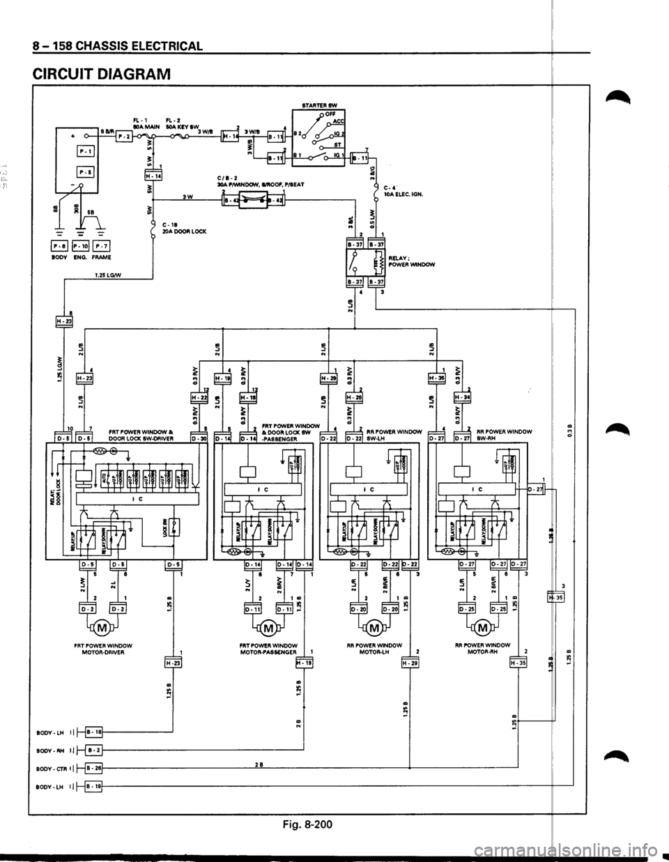
8 -158 CHASSIS ELECTRICAL
CIRCUIT DIAGRAM
8TARTERSW
FL-1 FL-2
-II
.-----, S Bill 80A MAIN lOA KEY IW o--t---1 P. 2 ~ -<>"" 3 W/1
B .. !!:
+
"' I fP7 ~ H-14 C/1-2 1i .. ~ 30A P/WINDOW, I/IIOOF, P/IEAT
~---~3W~--~~~--------~
~
~ C-4· lOA ELEC. IGN.
"' ci i
., Iii 58
--~
E!JIP-Iol(!3 BODY ENG. FRAME
i ..
~F:d IB-37IIB-37
I p ] RELAY; I I 9 J POWER WINDOW
C-18 20A DOOR LOCK
1.25 LG/W
4 3 ~~~-37
~ N ~----------------------------~--,
~ 4 ~ I ~
~ .. .. ~
~-2~ :·It ra :·2t ~-28
a FRT POWER WINDOW ~ 1= ~ 1=~ FRT POWER WINDOW I< 1= ~ ~ I< DOOR LOCK SW d l=lJ, RR POWER WINDOW
r-'-1..;;. oor-s"'" '"'"' 1 oo,-..;;. 55.__ I_;;;.Do'"'o"'R..;;.Lo;..;CK=.;sw.;..-OR=.;IV..;;.ER'---.o;; 1oo., --~30 o-141 -PASSENGER o-221 ID -221 sw-LH
~ ~-~~~i~ II ~" ~ ~" ~
i§ I I c IO ~ ~
~ ~ •J ~~h ~r~ lrt=H•
i~~ I[ . ~~~ iL4J_ il~
... ..
2 I
D-2 D-2
M
FRT POWER WINDOW MOTOR-DRIVER
H-23
Ill
s
BODY· LH II B • IBf---------___J
~g,-~ ~g,-~~~ e 1 1
~ i N N
D-11
M
I Ill Ill D-11 ,..:
FRT POWER WINDOW MOTOR-PASSENGER I
Ill N
-19
BODY-RH II r-8f---------------------------------....l'
,-!-
.
~ 5 ~~ e r=3
~ ~ N Ill N 2 I Ill
D-20 0-20 l(l ,..:
M
FIR POWER WINDOW
MOTOII-LH 2
H
-29
I ~ H-35 .. ci
!:
:~ lM·-·~· D-27 BW-RH
~ 1~ I
I C H-s-
lo ~ -A
!~ ~ i[~t
~ v
~ s ~~~ 6 3 ~ ~ Ill .. N ~ 2 I Ill l(l D-25 D-25 ,..:
M
I RR POWER WINDOW MOTOR-RH 2
1
H -35
Ill :e ,..:
BODY-CTR II 8-261---------------------------'2'-"8'---------------------------+-------\
-----------'
Ill .. 0
3
35
Ill l(l ,..:
BODY-LH lj B • 19f---------------------------------------------------------------------\
--------it---'
Fig. 8-200
~
~
Page 1368 of 1928
8 -178 CHASSIS ELECTRICAL
ANTI-LOCK BRAKE SYSTEM (ABS)
GENERAL DESCRIPTION
The circuit consists of the starter switch, stoplight switch (vehicle w/o cruise control), brake switch (vehicle
with cruise control), hydraulic unit, electronic brake control module, wheel speed sensor, G sensor, ABS and
4WD indicator, 4WD switch and data link connector.
When the service brake is applied while in the running mode,
the EBCM (Electronic Brake Control Module)
judges
which wheel is about to lock by using the wheel rotation speed signals sent from the four ABS speed
sensors at the
front and rear wheels. And the brake fluid pressure applied to the four wheels is controlled by
a hydraulic unit to prevent the wheels from locking.
Based on the wheel rotation speed signals
input from the ABS sensor, the EBCM sends out signals to the
solenoid valve in the hydraulic unit
to increase, maintain or decrease the brake fluid pressure. The solenoid
valve uses this signal
to control the fluid pressure which is applied to the calipers of the disk brakes of the
front wheels. (The system also controls at the same time the fluid pressure applied to the rear wheels.)
• EBCM (Electronic brake control module)
The EBCM uses the signals sent from the speed sensor to control the operation of the hydraulic unit.
When any malfunction occurs in the ABS, the
EBCM activates the fail-safe fuction while turning on the
ABS warning light.
• Hydraulic unit
The hydraulic unit consists of the motor, plunger pump, solenoid valve, and fluid pressure control
valves. The exterior
of the unit has a relay box consisting of the motor relay and valve relay. Three
solenoid valves, the
two of which are provided at the front wheels and the one at the rear wheels, control
the fluid pressure
of these wheels.
• Speed sensor
The speed sensor consists of the sensor and the rotor. It sends the EBCM the AC voltage generated by
the rotation of the rotor as the vehicle speed signal. ~
• G-sensor
The G-sensor, installed inside the center console, sends out signals to the EBCM by detecting the
decelerating speed
of the vehicle.
• ABS warning light
The ABS warning light in the instrument panel, lights up when any malfunction occurs in the ABS. It also
lights up
with the starter key at the "ON" position, as a self-check.
Refer
to Section 5A4, "ANTI-LOCK BRAKE SYSTEM" for detail.
II
Page 1392 of 1928
<(
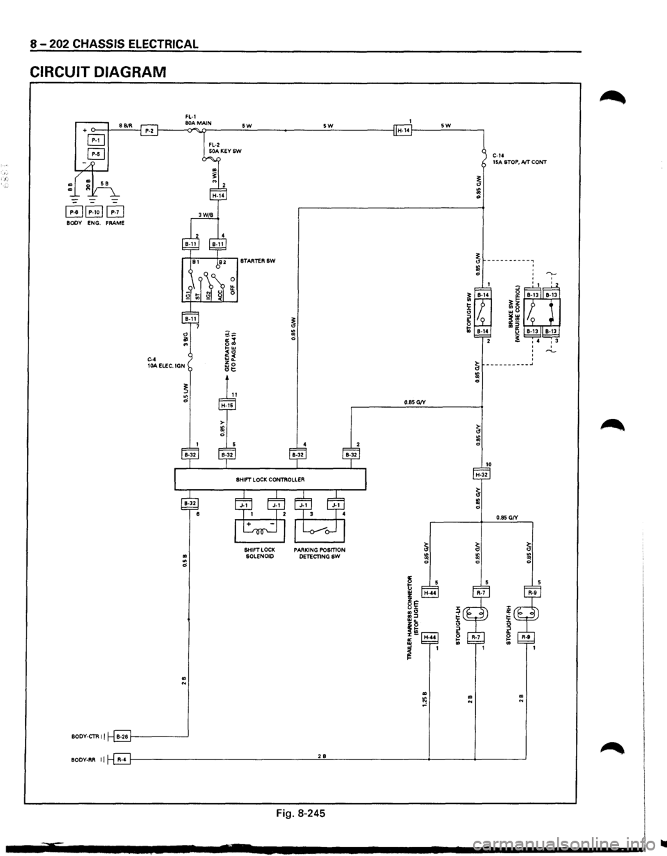
8 -202 CHASSIS ELECTRICAL
CIRCUIT DIAGRAM
FL-1 + o--t---'8'-'Bi::.:R-'--j P-2 f-----<80)"A~M>i.ATIN ___ _;_5..::W:.__ ______ :.__5:_:W:;_ _____ --I H-14f----_:5_:W:.._ __ ---,
B
B
~~P-1oj~ BODY ENG. FRAME
.. .. 0
.. N
BODY-CTR II B-26 1-------'
FL-2 50A KEYSW
0 !!: 0
SHIFT LOCK SOLENOID PARKING POSmON
DETECTINGSW
C-14 15A STOP, A/T CONT
BODY-RR II R-4 f---------------------'2'-'B'------------4-----4------'
Fig. 8-245
..
Page 1460 of 1928
8-270 CHASSIS ELECTRICAL
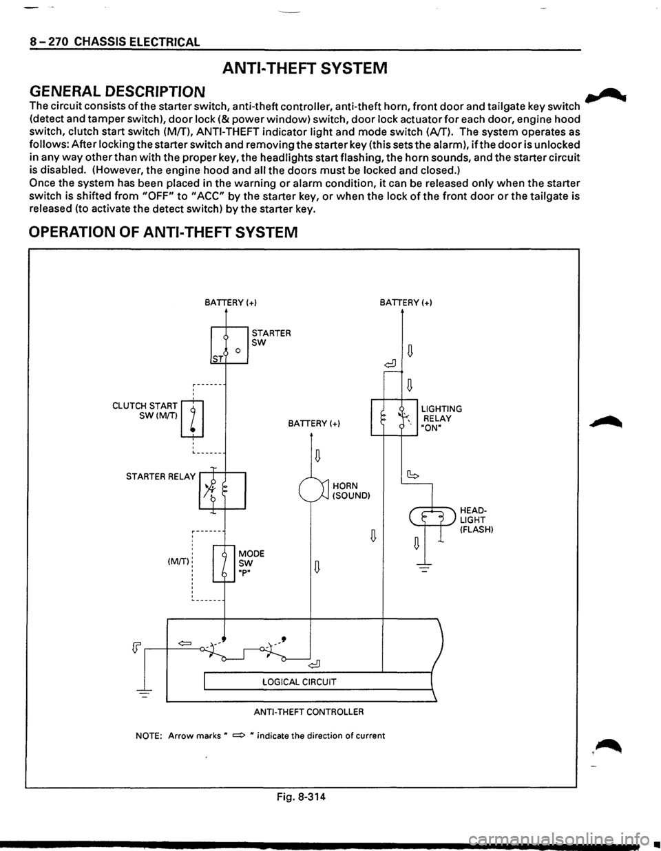
ANTI-THEFT SYSTEM
GENERAL DESCRIPTION .......
The circuit consists ofthe starter switch, anti-theft controller, anti-theft horn, front door and tailgate key switch
(detect and tamper switch),
door lock (&power window) switch, door lock actuator for each door, engine hood
switch, clutch start switch (MfT),
ANTI-THEFT indicator light and mode switch (AfT). The system operates as
follows: After locking the starter switch and removing the starter key (this sets the alarm),
ifthe door is unlocked
in any
way other than with the proper key, the headlights start flashing, the horn sounds, and the starter circuit
is disabled. (However,
the engine hood and all the doors must be locked and closed.)
Once the system has been placed in the warning or alarm condition, it can be released only when the starter
switch is shifted
from "OFF" to "ACC" by the starter key, or when the lock of the front door or the tailgate is
released (to activate the detect switch)
by the starter key.
OPERATION OF ANTI-THEFT SYSTEM
'
'
CLUTCH START m
SW(M/Tiw
' '
'
BATIERY(+)
0 ST
STARTER sw
BATIERY(+)
L------
STARTER RELAY
' ' (MIT):
'
'
'
HORN
(SOUND)
ANTI-THEFT CONTROLLER
BATIERY(+)
LIGHTING
RELAY
"ON"
HEADLIGHT (FLASH)
NOTE: Arrow marks u ~ u indicate the direction of current
Fig. 8-314
•
Page 1461 of 1928
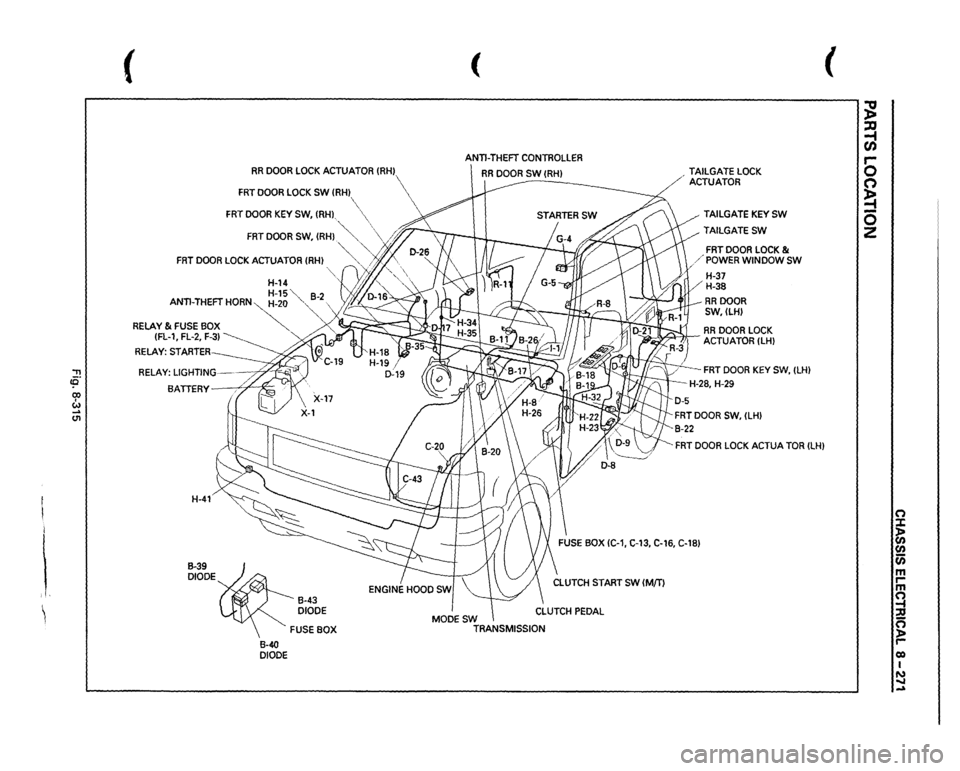
'"T1 !fl' co I w _. (11
I i i, ~
(
RR
DOOR
LOCK
ACTUATOR
{RHJ
FRT
DOOR
LOCK
SW
(RH
FRT
DOOR
KEY
SW,
(RH),
( ANTI-THEFT
CONTROLLER
RR
DOOR
SW
(RHJ
-------
FRT
DOOR
SW,
(RH)
.~""··
\
/;'~
~
"'··
FRT
DOOR
LOCK
ACTUATOR
(RH)
'-, ..,/j.
',
H-14
'L
y'JIJ.
"·,
H-15"
82
ANTI-THEFT
HORN~-20
"-,
-
RELAY
& FUSE
BOX
~
{FL-1,
FL-2,
F-3)
~
RELAY:
STARTER BATTERY
X::
H-41 B-39 DIODE
B-40 DIODE
B-43 DIODE FUSE
BOX MODESW
TRANSMISSION ,
TAILGATE
LOCK
ACTUATOR
TAILGATE
KEY
SW
TAILGATESW
FRT
DOOR
LOCK
&
/'POWER
WINDOW
SW
H-37 H-38 RRDOOR SW,(LH)
.
RR
DOOR
LOCK
-~ACTUATOR
{LHJ
FRT
DOOR
KEY
SW,
{LH)
-H-28,
H-29
FRT
DOOR
LOCK
ACTUA
TOR
(LH)
(
;g ~ C/) 5 C') ~ 0 z
n :X: ~ (/) 0 m rm ~ n ):a r-0) I N ..... -