engine ISUZU TROOPER 1995 Workshop Manual
[x] Cancel search | Manufacturer: ISUZU, Model Year: 1995, Model line: TROOPER, Model: ISUZU TROOPER 1995Pages: 1928
Page 566 of 1928
6A1-8 ENGINE (V6 3.2L DOHC AND SOHC)
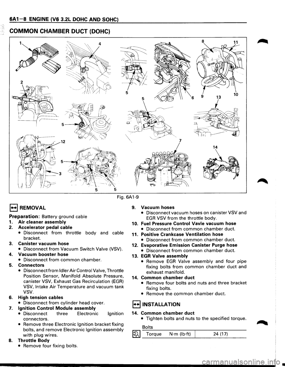
COMMON CHAMBER DUCT (DOHC)
8
11
5
5
6
7
14
5 5
Fig. 6A1-9
E) REMOVAL
Preparation: Battery ground cable
1. Air cleaner assembly
2. Accelerator pedal cable
• Disconnect from throttle body and cable
bracket.
3. Canister vacuum hose
• Disconnect from Vacuum Switch Valve (VSV).
4. Vacuum booster hose
• Disconnect from common chamber.
5. Connectors
• Disconnect from Idler Air Control Valve, Throttle
Position Sensor, Manifold Absolute Pressure,
canister VSV, Exhaust Gas Recirculation (EGR)
VSV, Intake Air Temperature and vacuum tank
vsv.
6. High tension cables
• Disconnect from cylinder head cover.
7. Ignition Control Module assembly
• Disconnect three Electronic Ignition
connectors.
• Remove three Electronic Ignition bracket fixing
bolts, and remove Electronic Ignition assembly
with plug wires.
8. Throttle Body
• Remove four fixing bolts.
9. Vacuum hoses
• Disconnect vacuum hoses on canister VSV and
EGR VSV from the throttle body.
10. Fuel Pressure Control Vavle vacuum hose
• Disconnect from common chamber duct.
11. Positive Crankcase Ventilation hose
• Disconnect from common chamber duct.
12. Evaporative Emission Canister Purge hose
• Disconnect from common chamber duct.
13. EGR Valve assembly
• Remove EGR Valve assembly and four pipe
fixing bolts from common chamber duct and
exhaust manifold.
14. Common chamber duct
• Remove four bolts and nuts and three bracket
fixing bolts.
• Remove the common chamber duct.
l·u·IINSTALLATION
14. Common chamber duct
• Tighten bolts and nuts to the specified torque.
Bolts
~~~ Torque N·m (lb·ft) 24 (17)
•
Page 567 of 1928
Nuts
~~~ Torque N·m (lb·ft) 24 (17)
13. Exhaust Gas Recirculation Valve assembly
• Tighten bolts to the specified torque.
Exhaust Gas Recirculation
Valve Side
~~~ Torque N·m (lb·in) I 8 (69)
Exhaust Manifold Side
~~~ Torque N·m (lb·ft) 28 (21)
12. Evaporative Emission Canister Purge hose
11. Positive Crankcase Vantilatlon hose
10. Fuel Pressure Control Valve vacuum hose
8. Throttle body
• Tighten bolts to the specified torque.
~~~ Torque N·m (lb·ft) I 19 (14)
9. Vacuum hose
• Connect vacuum hoses on canister Vacuum
Switching Valve
and Exhaust Gas Recirculation
Vacuum Switching Valve to the throttle body.
7. Ignition Control Module assembly
• Tighten bolts to the specified torque and
connect connector.
~~~ Torque N·m (lb·ft)
6. High tension cables
5. Connectors
• Connect each connector.
4. Vacuum booster hose
3. Canister vacuum hose
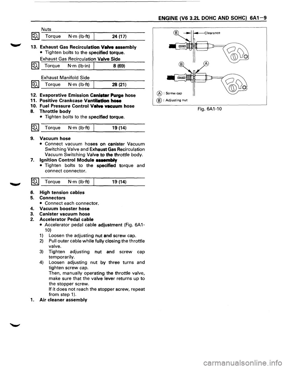
2. Accelerator Pedal cable
19 (14)
• Accelerator pedal cable adjustment (Fig. 6A 1-
10)
1) Loosen the adjusting nut and screw cap.
2) Pull outer cable while fully closing the throttle
valve.
3) Tighten adjusting nut and screw cap
temporarily.
4) Loosen adjusting nut by three turns and
tighten screw cap.
Then,
manually operating the throttle valve,
make sure that the valve lever returns up to
the stopper screw.
If it does not reach the stopper screw, repeat
from step 1 ).
1. Air cleaner assembly
ENGINE (V6 3.2L DOHC AND SOHC) 6A 1-9
@:Screw cap
@ : Adjusting nut
Fig. 6A1-10
Page 568 of 1928
6A 1 1 0 ENGINE (V6 3.2L DOHC AND SOHC)
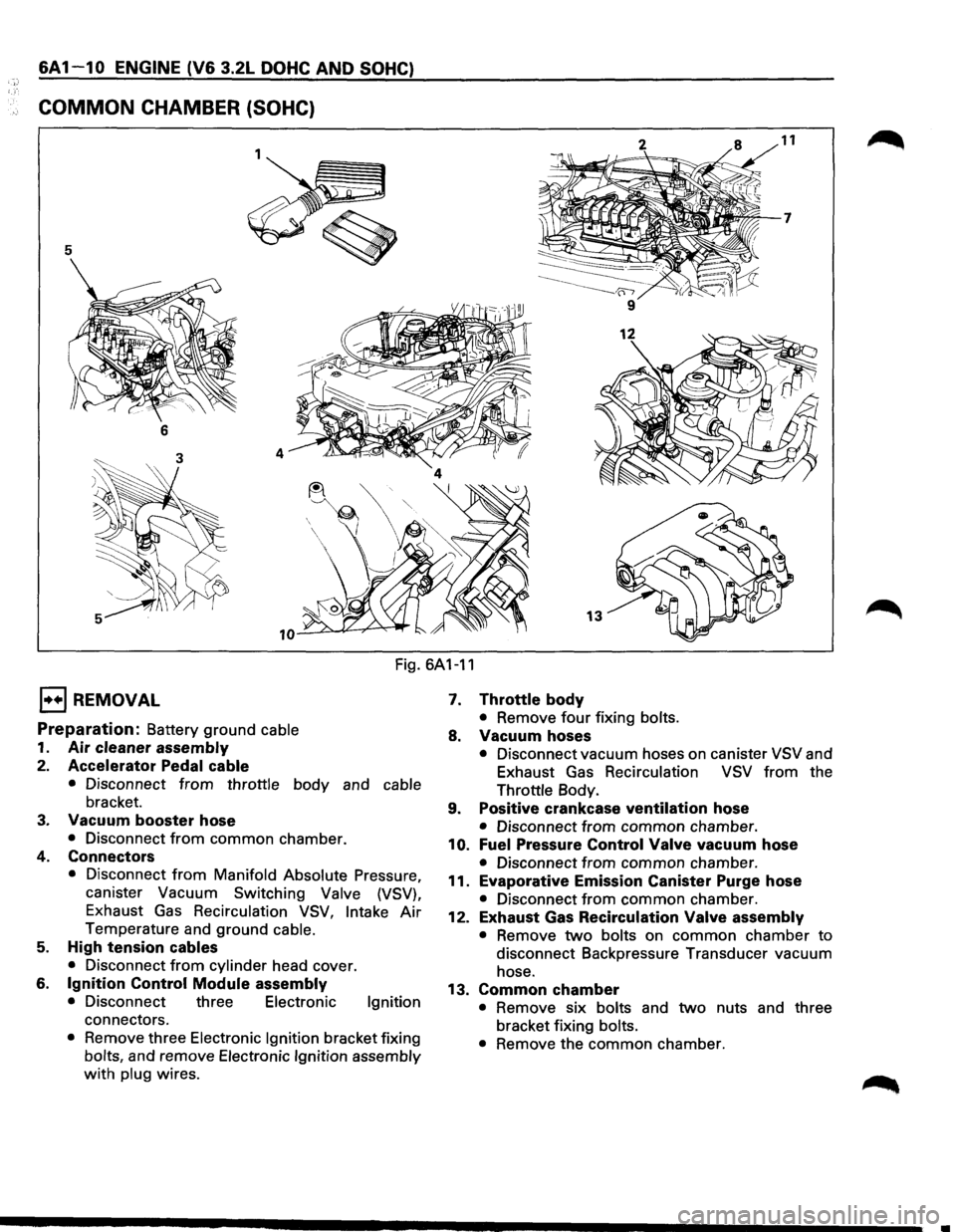
COMMON CHAMBER (SOHC)
5
6
13
Fig. 6A1-11
1••1 REMOVAL
Preparation: Battery ground cable
1. Air cleaner assembly
2. Accelerator Pedal cable
• Disconnect from throttle body and cable
bracket.
3. Vacuum booster hose
• Disconnect from common chamber.
4. Connectors
• Disconnect from Manifold Absolute Pressure,
canister Vacuum Switching
Valve (VSV),
Exhaust Gas Recirculation VSV, Intake Air
Temperature and ground cable.
5. High tension cables
• Disconnect from cylinder head cover.
6. Ignition Control Module assembly
• Disconnect three Electronic Ignition
connectors.
• Remove three Electronic Ignition bracket fixing
bolts, and remove Electronic Ignition assembly
with plug wires.
7. Throttle body
• Remove four fixing bolts.
8. Vacuum hoses
• Disconnect vacuum hoses on canister VSV and
Exhaust Gas
Recirculation VSV from the
Throttle Body.
9. Positive crankcase ventilation hose
• Disconnect from common chamber.
10. Fuel Pressure Control Valve vacuum hose
• Disconnect from common chamber.
11. Evaporative Emission Canister Purge hose
• Disconnect from common chamber.
12. Exhaust Gas Recirculation Valve assembly
• Remove two bolts on common chamber to
disconnect Backpressure Transducer vacuum
hose.
13. Common chamber
• Remove six bolts and two nuts and three
bracket fixing
bolts.
•
Remove the common chamber.
Page 569 of 1928
I••IINSTALLATION
13. Common chamber
~ • Tighten bolts and nuts to the specified torque.
~
Bolts
1~1 Torque N·m (lb·ft) 24 (17)
Nut
~~~ Torque N·m (lb·ft) 24 (17)
12. Exhaust Gas Recirculation Valve assembly
• Tighten bolts to the specified torque.
~~~ Torque N·m (lb·in) I 9 (78)
11. Evaporative Emission Canister Purge hose
9. Positive Crankcase Ventilation hose
1
0. Fuel Pressure Control Valve vacuum hose
7. Throttle body
• Tighten bolts to the specified torque.
~~~ Torque N·m (lb·ft) I 22 (16)
8. Vacuum hose
6.
~
5.
4.
3.
2.
• Connect vacuum hoses on canister Vacuum
Switching Valve and Exhaust
Gas Recirculation
Vacuum Switching Valve to the Throttle Body.
Ignition Control Module assembly
• Tighten bolts to the specified torque and
connect connector.
Torque
N·m (lb·ft)
High tension cables
Connectors
22 (16)
• Connect each connector without fail.
Vacuum booster hose
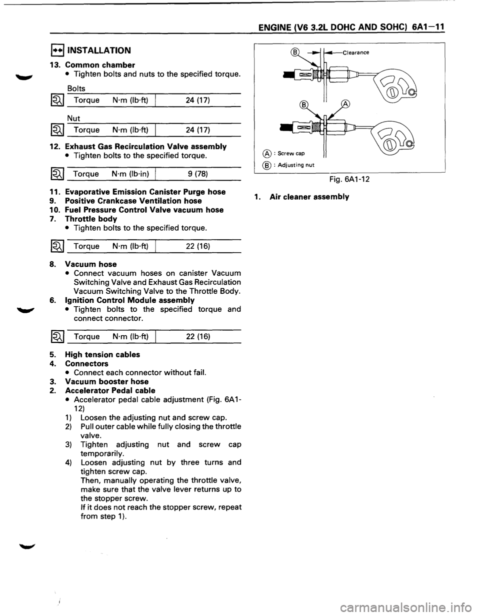
Accelerator Pedal cable
• Accelerator pedal cable adjustment (Fig. 6A 1-
12)
1) Loosen the adjusting nut and screw cap.
2) Pull outer cable while fully closing the throttle
valve.
3) Tighten adjusting nut and screw cap
temporarily.
4) Loosen adjusting nut by three turns and
tighten screw cap.
Then, manually operating the throttle valve,
make sure that the valve lever returns up to
the stopper screw.
If it does not reach the stopper screw, repeat
from step 1 ).
ENGINE (V6 3.2L DOHC AND SOHC) 6A1-11
@:Screw cap
@ :Adjusting nut
Fig. 6A1-12
1. Air cleaner assembly
Page 570 of 1928
1"!
6A 1-12 ENGINE (V6 3.2L DOHC AND SOHC)
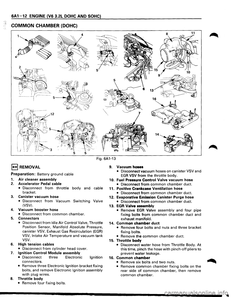
COMMON CHAMBER (DOHC)
Fig. 6A1-13
l•+l REMOVAL
Preparation: Battery ground cable
1. Air cleaner assembly
2. Accelerator Pedal cable
• Disconnect from throttle body and cable
bracket.
3. Canister vacuum hose
• Disconnect from Vacuum Switching Valve
(VSV).
4.
Vacuum booster hose
• Disconnect from common chamber.
5. Connectors
• Disconnect from Idle Air Control Valve, Throttle
Position Sensor, Manifold Absolute Pressure,
canister VSV, Exhaust Gas Recirculation (EGR)
VSV, Intake Air Temperature and vacuum tank
vsv.
6. High tension cables
•
Disconnect from cylinder head cover.
7. Ignition Control Module assembly
• Disconnect three Electronic Ignition
connectors.
• Remove three Electronic Ignition bracket fixing
bolts, and remove Electronic Ignition assembly
with plug wires.
8. Throttle body
• Remove four fixing bolts.
9. Vacuum hoses
• Disconnect vacuum hoses on canister VSV and
EGR VSV from the throttle body.
10. Fuel Pressure Control Valve vacuum hose
• Disconnect from common chamber duct.
11.
Positive Crankcase Ventilation hose
• Disconnect from common chamber duct.
12.
Evaporative Emission Canister Purge hose
• Disconnect from common chamber duct.
13.
EGR Valve assembly
• Remove EGA Valve assembly and four pipe
fixing
bolts from common chamber duct and
exhaust
manifold.
14. Common chamber duct
• Remove four bolts and nuts and three bracket
fixing
bolts.
•
Remove the common chamber duct.
15.
Throttle body
• Disconnect water hose from Throttle Body. At
this time, pinch the hose with pinch-off pliers to
prevent water leakage.
16. Common chamber
• Remove six bolts and two nuts. ~
• Remove common chamber fixing bolts on the
rear side
of common chamber, then remove
common chamber.
1111
Page 571 of 1928
l·u·IINSTALLATION
16. Common chamber
• Tighten bolts and nuts to the specified torque.
Bolts
1«1 Torque N·m (lb·ft) 24 (17)
Nuts
1«1 Torque N·m (lb·ft) 24 (17)
15. Throttle body
• Connect the water hose securely.
14. Common chamber duct
• Tighten bolts and nuts to the specified torque.
Bolts
~ Torque N·m (lb·ft) 24 (17)
Nuts
~ Torque N·m (lb·ft) 24 (17)
13. Exhaust Gas Recirculation Valve assembly
• Tighten bolts to the specified torque.
Exhaust Gas Recirculation Valve
Side
1«1 Torque N·m (lb·in) I 8 (69)
Exhaust Manifold Side
1«1 Torque N·m (lb·ft) 28 (21)
12. Evaporative Emission Canister Purge hose
11. Positive Crankcase Ventilation hose
10. Fuel Pressure Control Valve vacuum hose
8. Throttle body
• Tighten bolts to the specified torque.
1«1 Torque N·m (lb·ft) I 19 (14)
9. Vacuum hose
• Connect vacuum hoses on canister Vacuum
Switching Valve and Exhaust Gas Recirculation
Vacuum
Switching Valve to the throttle body.
7. Ignition Control Module assembly
• Tighten bolts to the specified torque and
connect connector.
1«1 Torque N·m (lb·ft)
6. High tension cables
5. Connectors
• Connect each connector.
4. Vacuum booster hose
3. Canister vacuum hose
19 (14)
ENGINE (V6 3.2L DOHC AND SOHC) 6A 1-13
2. Accelerator Pedal cable
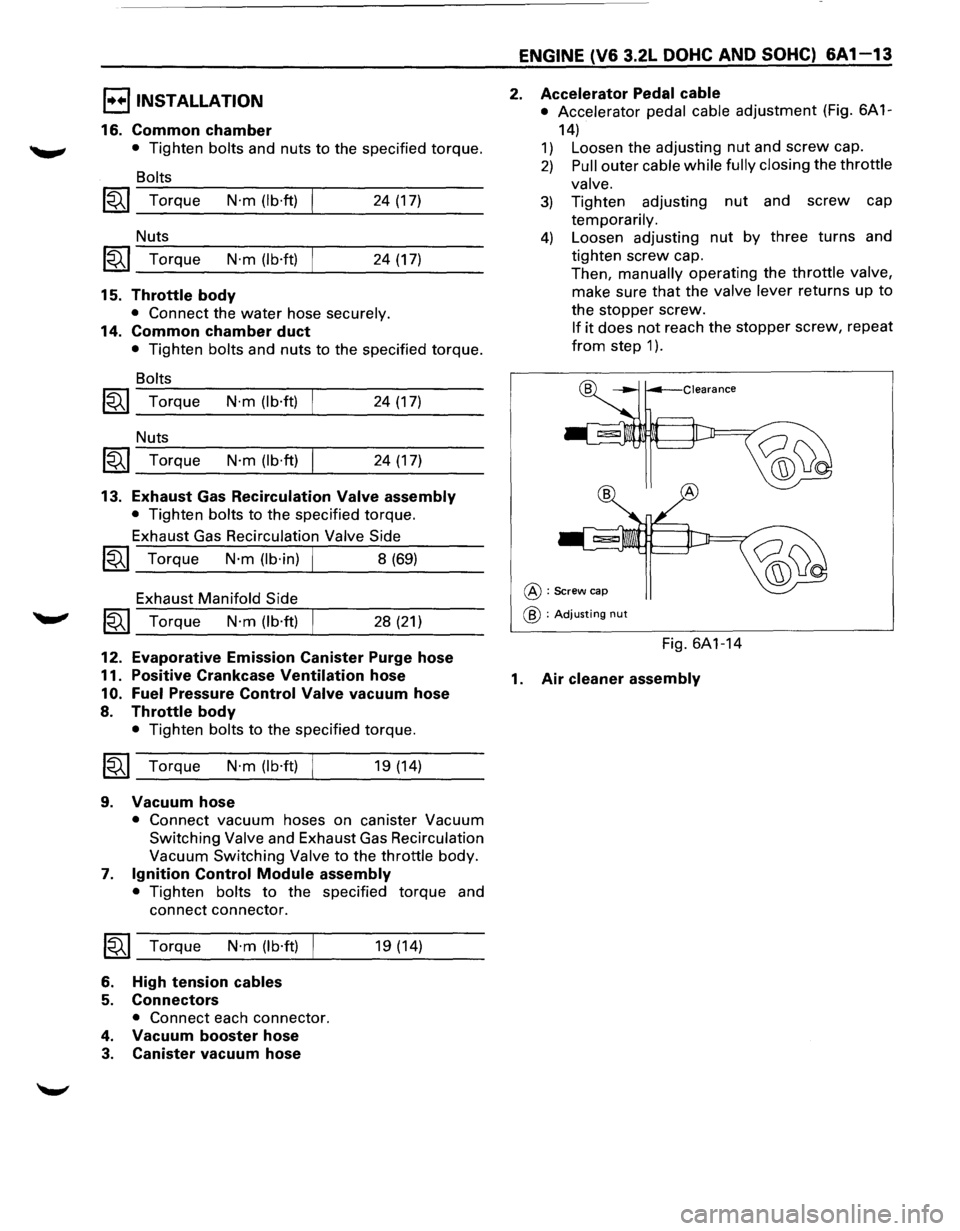
• Accelerator pedal cable adjustment (Fig. 6A 1-
14)
1) Loosen the adjusting nut and screw cap.
2) Pull outer cable while fully closing the throttle
valve.
3) Tighten adjusting nut and screw cap
temporarily.
4) Loosen adjusting nut by three turns and
tighten screw cap.
Then, manually operating the
throttle valve,
make sure that the valve lever returns up to
the stopper screw.
If it does not reach the stopper screw, repeat
from step 1 ).
@:Screw cap
@ : Adjusting nut
Fig. 6A1-14
1. Air cleaner assembly
Page 572 of 1928
6A1-14 ENGINE (V6 3.2L DOHC AND SOHC)
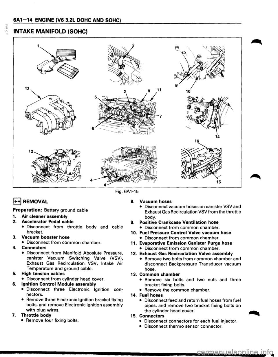
INTAKE MANIFOLD (SOHC}
13 10
7
6
14
4 15
Fig. 6A1-15
1••1 REMOVAL
Preparation: Battery ground cable
1. Air cleaner assembly
2. Accelerator Pedal cable
• Disconnect from throttle body and cable
bracket.
3. Vacuum booster hose
• Disconnect from common chamber.
4. Connectors
• Disconnect from Manifold Aboslute Pressure,
canister Vacuum Switching Valve (VSV),
Exhaust
Gas Recirculation VSV, Intake Air
Temperature and ground cable.
5. High tension cables
• Disconnect from cylinder head cover.
6. Ignition Control Module assembly
• Disconnect three Electronic Ignition con
nectors.
• Remove three Electronic Ignition bracket fixing
bolts, and remove Electronic Ignition assembly
with plug wires.
7. Throttle body
• Remove four fixing bolts.
8. Vacuum hoses
• Disconnect vacuum hoses on canister VSV and
Exhaust Gas Recirculation VSV
from the throttle
body.
9. Positive Crankcase Ventilation hose
• Disconnect from common chamber.
10. Fuel Pressure Control Valve vacuum hose
• Disconnect from common chamber.
11. Evaporative Emission Canister Purge hose
• Disconnect from common chamber.
12. Exhaust Gas Recirculation Valve assembly
• Remove two bolts from common chamber and
disconnect Backpressure Transducer vacuum
hose.
13. Common chamber
• Remove six bolts and two nuts and three
bracket fixing bolts.
• Remove the common chamber.
14. Fuel hoses
• Disconnect feed and return fuel hoses from fuel
pipes, and remove two bracket fixing bolts on
the cylinder head cover.
15. Connectors
• Disconnect connectors for each fuel injector.
• Disconnect thermo sensor connector.
•
Page 573 of 1928
16. Intake manifold
• Remove two fixing bolts and four nuts, then
remove the intake
manifold.
I••IINSTALLATION
16. Intake manifold
• Tighten bolts and nuts to the specified torque.
Bolts
~~~ Torque N·m (lb·ft) 24 (17)
Nuts
1~1 Torque N·m (lb·ft) 24 (17)
15. Connectors
• Connect each connector.
14. Fuel hoses
• Connect the hoses securely and install bolts on
the head cover.
13. Common chamber
• Tighten bolts and nuts to the specified torque.
Bolts
~~~ Torque N·m (lb·ft) 24 (17)
Nuts
~~~ Torque N·m (lb·ft) 24 (17)
12. Exhaust Gas Recirculation Valve assembly
• Tighten bolts to the specified torque.
~~~ Torque N·m (lb·in) I 9 (78)
11. Evaporative Emission Canister Purge hose
10. Fuel Pressure Control Valve vacuum hose
9. Positive Crankcase Ventilation hose
7. Throttle body
• Tighten bolts to the specified torque.
~~~ Torque N·m (lb·ft) I 22 (16)
8. Vacuum hose
• Connect vacuum hoses on canister Vacuum
Switching Valve and Exhaust Gas Recirculation
Vacuum
Switching Valve to the throttle body.
6. Ignition Control Module assembly
• Tighten bolts to the specified torque and
connect connector.
~~~ Torque N·m (lb·ft) 22 (16)
5. High tension cables
4. Connectors
• Connect each connector without fail.
3. Vacuum booster hose
ENGINE (V6 3.2L DOHC AND SOHC) 6A1-15
2. Accelerator Pedal cable
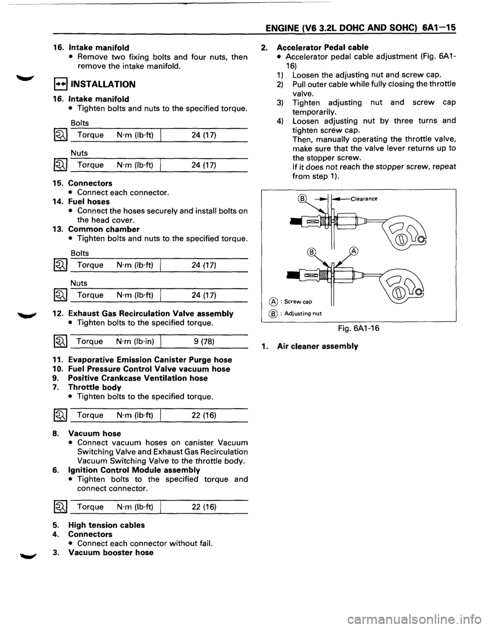
• Accelerator pedal cable adjustment (Fig. 6A 1-
16)
1) Loosen the adjusting nut and screw cap.
2) Pull outer cable while fully closing the throttle
valve.
3) Tighten adjusting nut and screw cap
temporarily.
4) Loosen adjusting nut by three turns and
tighten
screw cap.
Then,
manually operating the throttle valve,
make sure that the valve lever returns up to
the stopper screw.
If it does not reach the stopper screw, repeat
from step 1 ).
@:Screw cap
@ : Adjusting nut
Fig. 6A1-16
1. Air cleaner assembly
Page 574 of 1928
.,
6A1-16 ENGINE (V6 3.2L DOHC AND SOHC}
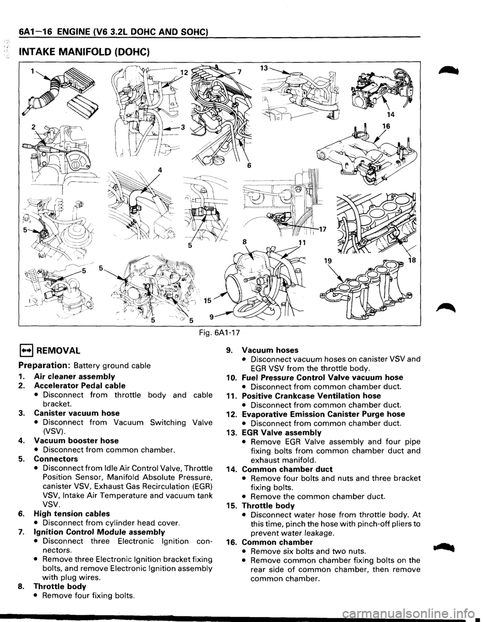
INTAKE MANIFOLD (DOHC)
Fig. 6A1-17
1••1 REMOVAL
Preparation: Battery ground cable
1. Air cleaner assembly
2. Accelerator Pedal cable
• Disconnect from throttle body and cable
bracket.
3. Canister vacuum hose
• Disconnect from Vacuum Switching Valve
(VSV).
4. Vacuum booster hose
• Disconnect from common chamber.
5. Connectors
• Disconnect from Idle Air Control Valve, Throttle
Position Sensor, Manifold Absolute Pressure,
canister
VSV, Exhaust Gas Recirculation (EGR)
VSV, Intake Air Temperature and vacuum tank
vsv.
6. High tension cables
• Disconnect from cylinder head cover.
7. Ignition Control Module assembly
• Disconnect three Electronic Ignition con
nectors.
• Remove three Electronic Ignition bracket fixing
bolts, and remove Electronic Ignition assembly
with plug wires.
8. Throttle body
• Remove four fixing bolts.
9. Vacuum hoses
• Disconnect vacuum hoses on canister VSV and
EGR VSV from the throttle body.
10. Fuel Pressure Control Valve vacuum hose
• Disconnect from common chamber duct.
11. Positive Crankcase Ventilation hose
• Disconnect from common chamber duct.
12. Evaporative Emission Canister Purge hose
• Disconnect from common chamber duct.
13. EGR Valve assembly
• Remove EGR Valve assembly and four pipe
fixing
bolts from common chamber duct and
exhaust
manifold.
14. Common chamber duct
• Remove four bolts and nuts and three bracket
fixing
bolts.
•
Remove the common chamber duct.
15. Throttle body
• Disconnect water hose from throttle body. At
this time, pinch the hose with pinch-off pliers to
prevent water leakage.
16. Common chamber
• Remove six bolts and two nuts.
• Remove common chamber fixing bolts on the
rear side
of common chamber, then remove
common chamber.
•
Page 575 of 1928
... t&:?
17. Fuel hoses
• Disconnect feed and return fuel hoses from fuel
pipes, and remove
two bracket fixing bolts on
the cylinder head cover.
18. Fuel injector connectors
• Disconnect from injectors.
19. Intake manifold
• Remove engine harness bracket on RH side.
• Remove two bolts and four nuts, and remove
intake manifold.
I••IINSTALLATION
19. Intake manifold
• Tighten bolts and nuts to the specified torque.
Bolts
~~~ Torque N·m (lb·ft) 24 (17)
Nuts
~~~ Torque N·m (lb·ft) 24 (17)
18. Fuel injector connectors
• Connect each connector.
17. Fuel hoses
• Connect the hoses securely and install the bolts
on the head cover.
16. Common chamber
• Tighten bolts and nuts to the specified torque.
Bolts
~ Torque N·m (lb·ft) 24 (17)
Nuts
~ Torque N·m (lb·ft) 24 (17)
15. Throttle body
• Connect surely the water hose.
14. Common chamber duct
• Tighten bolts and nuts to the specified torque.
Bolts
~ Torque N·m (lb·ft) 24 (17)
Nuts
~ Torque N·m (lb·ft) 24 (17)
13. Exhaust Gas Recirculation Valve assembly
• Tighten bolts to the specified torque.
Exhaust Gas Recirculation Valve
Side
~~~ Torque N·m (lb·in) I 8 (69)
Exhaust Manifold Side
~~~ Torque N·m (lb·ft) 28 (21)
12. Evaporative Emission Canister Purge hose
11. Positive Crankcase
Ventilation hose
10. Fuel Pressure Control Valve vacuum hose
ENGINE (V6 3.2L DOHC AND SOHC) 6A1-17
8. Throttle body
• Tighten bolts to the specified torque.
~~~ Torque N·m (lb·ft) I 19 (14)
9. Vacuum hose
• Connect vacuum hoses on canister Vacuum
Switching Valve and Exhaust Gas Recirculation
Vacuum Switching Valve
to the throttle body.
7. Ignition Control Module assembly
• Tighten bolts to the specified torque and
connect connector.
~~~ Torque N·m (lb·ft) 19 (14)
6. High tension cables
5. Connectors
• Connect each connector without fail.
4. Vacuum booster hose
3. Canister vacuum hose
2. Accelerator Pedal cable
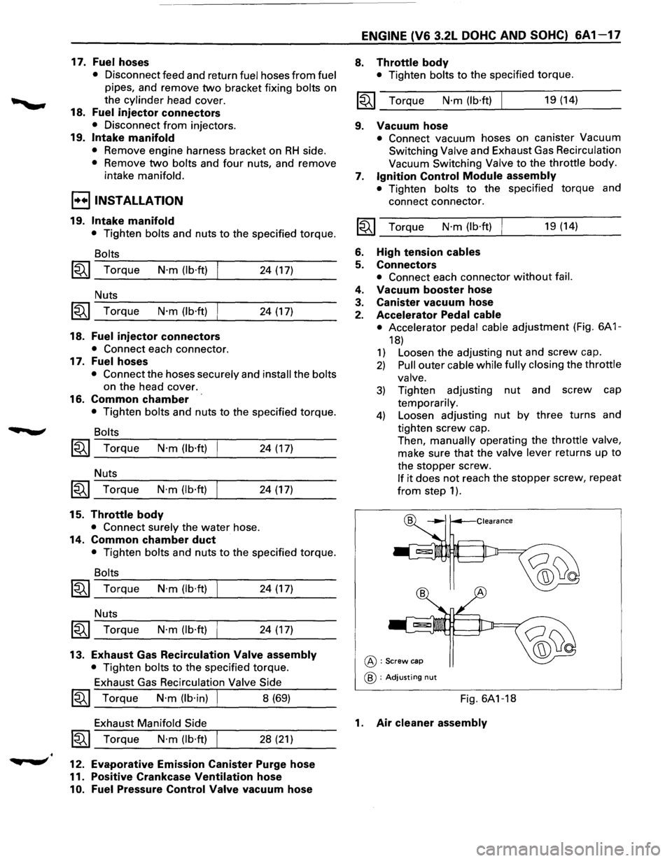
• Accelerator pedal cable adjustment (Fig. 6A 1-
18)
1) Loosen the adjusting nut and screw cap.
2) Pull outer cable while fully closing the throttle
valve.
3) Tighten adjusting nut and screw cap
temporarily.
4) Loosen adjusting nut by three turns and
tighten screw cap .
Then, manually operating the throttle valve,
make sure
that the valve lever returns up to
the stopper screw.
If it does not reach the stopper screw, repeat
from step 1 ).
@:Screw cap
@ : Adjusting nut
Fig. 6A1-18
1. Air cleaner assembly