engine ISUZU TROOPER 1995 Workshop Manual
[x] Cancel search | Manufacturer: ISUZU, Model Year: 1995, Model line: TROOPER, Model: ISUZU TROOPER 1995Pages: 1928
Page 525 of 1928
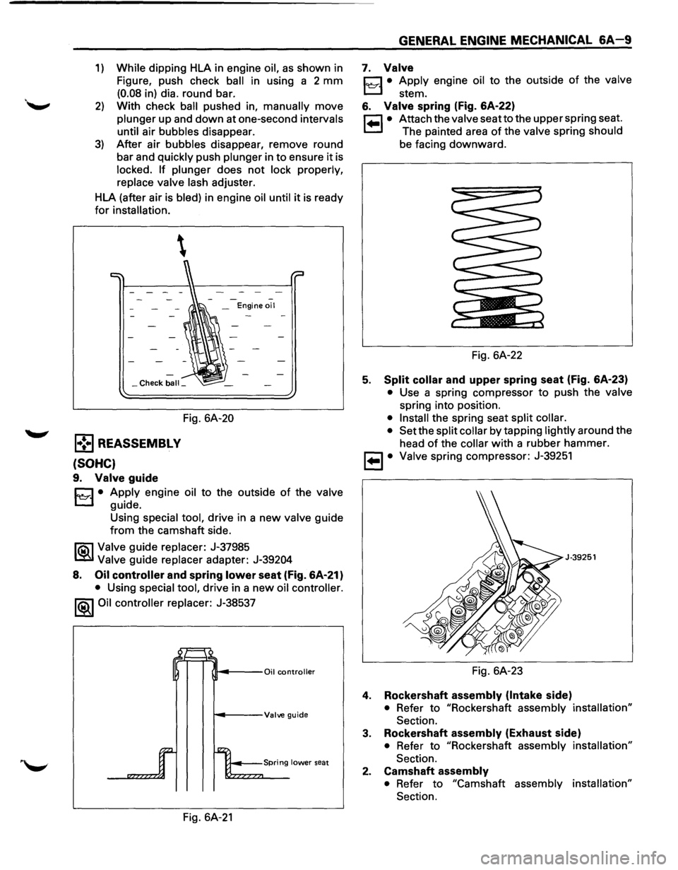
1) While dipping HLA in engine oil, as shown in
Figure, push check
ball in using a 2 mm
(0.08 in) dia. round bar.
2) With check ball pushed in, manually move
plunger up and down at one-second intervals
until
air bubbles disappear.
3) After air bubbles disappear, remove round
bar and
quickly push plunger in to ensure it is
locked. If plunger does not lock properly,
replace valve lash adjuster.
HLA (after air is
bled) in engine oil until it is ready
for installation.
-_ Engine oil
_Check ball_
Fig. 6A-20
l•!•l REASSEMBL V
(SOHC)
9. Valve guide
C1 • Apply engine oil to the outside of the valve
t..::::.l guide.
Using
special tool, drive in a new valve guide
from the camshaft side.
li5\l Valve guide replacer: J-37985
~ Valve guide replacer adapter: J-39204
8. Oil controller and spring lower seat (fig. 6A·21)
• Using special tool, drive in a new oil controller.
1®.1 Oil controller replacer: J-38537
~---Valve guide
Fig. 6A-21
GENERAL ENGINE MECHANICAL 6A-9
7. Valve
C1 • Apply engine oil to the outside of the valve
t..::::.l stem.
6. Valve spring (fig. 6A-22)
r=l • Attach the valve seatto the upper spring seat.
1.=.1 The painted area of the valve spring should
be facing downward.
Fig. 6A-22
5. Split collar and upper spring seat (Fig. 6A-23)
• Use a spring compressor to push the valve
spring into position.
• Install the spring seat split collar.
• Set
the split collar by tapping lightly around the
head
of the collar with a rubber hammer.
, ... ,. Valve spring compressor: J-39251
J·39251
Fig. 6A-23
4. Rockershaft assembly (Intake side)
• Refer to "Rockershaft assembly installation"
Section.
3. Rockershaft assembly (Exhaust side)
• Refer to "Rockershaft assembly installation"
Section.
2. Camshaft assembly
• Refer to "Camshaft assembly installation"
Section.
Page 526 of 1928
6A-1 0 GENERAL ENGINE MECHANICAL
1. Camshaft bracket fixing bolts
• Refer to "Camshaft assembly installation"
Section.
(DOHC)
10. Valve guide
D • Apply engine oil to the outside of the valve
l::::::J guide. Using special tool, drive in a new valve
guide from the camshaft side.
I'Qi1 Valve guide replacer: J-37985
~ Valve guide replacer adapter: J-39204
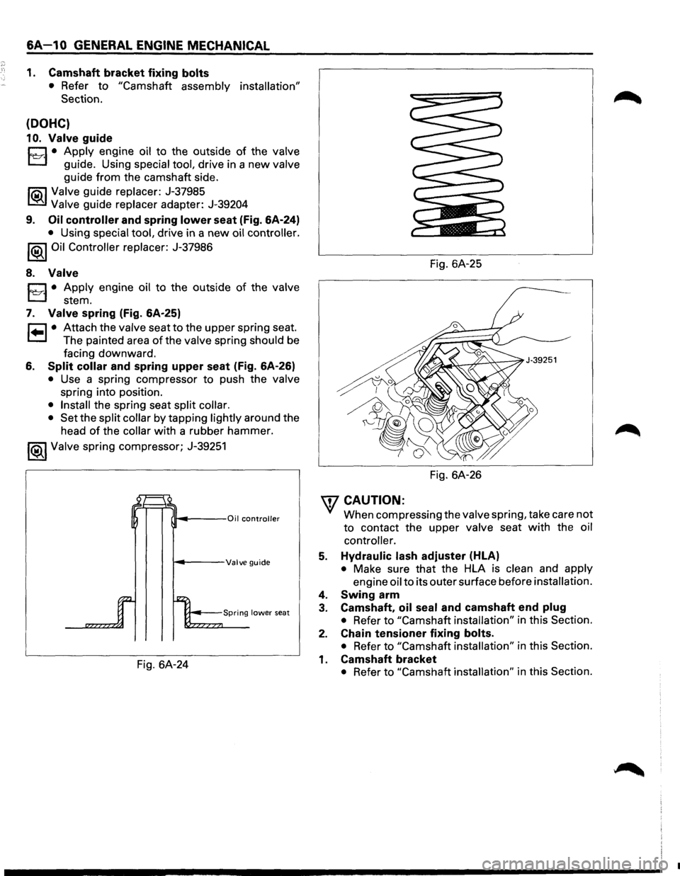
9. Oil controller and spring lower seat (Fig. 6A-24)
• Using special tool, drive in a new oil controller.
1®1 Oil Controller replacer: J-37986
8. Valve
D • Apply engine oil to the outside of the valve
l::::::J ste m .
7. Valve spring (Fig. 6A-25)
r:::l • Attach the valve seat to the upper spring seat.
1.=..1 The painted area of the valve spring should be
facing downward.
6. Split collar and spring upper seat (Fig. 6A-26)
• Use a spring compressor to push the valve
spring into position.
• Install the spring seat split collar.
• Set
the split collar by tapping lightly around the
head
of the collar with a rubber hammer.
I®J Valve spring compressor; J-39251
~---Valve guide
Fig. 6A-24 Fig.
6A-25
Fig. 6A-26
WCAUTION:
'V When compressing the valve spring, take care not
to contact the upper
valve seat with the oil
controller.
5. Hydraulic lash adjuster (HLA)
• Make sure that the HLA is clean and apply
engine oil to its outer surface before installation.
4. Swing arm
3. Camshaft, oil seal and camshaft end plug
• Refer to "Camshaft installation" in this Section.
2. Chain tensioner fixing bolts.
• Refer to "Camshaft installation" in this Section.
1. Camshaft bracket
• Refer to "Camshaft installation" in this Section.
•
Page 527 of 1928
GENERAL ENGINE MECHANICAL 6A-11
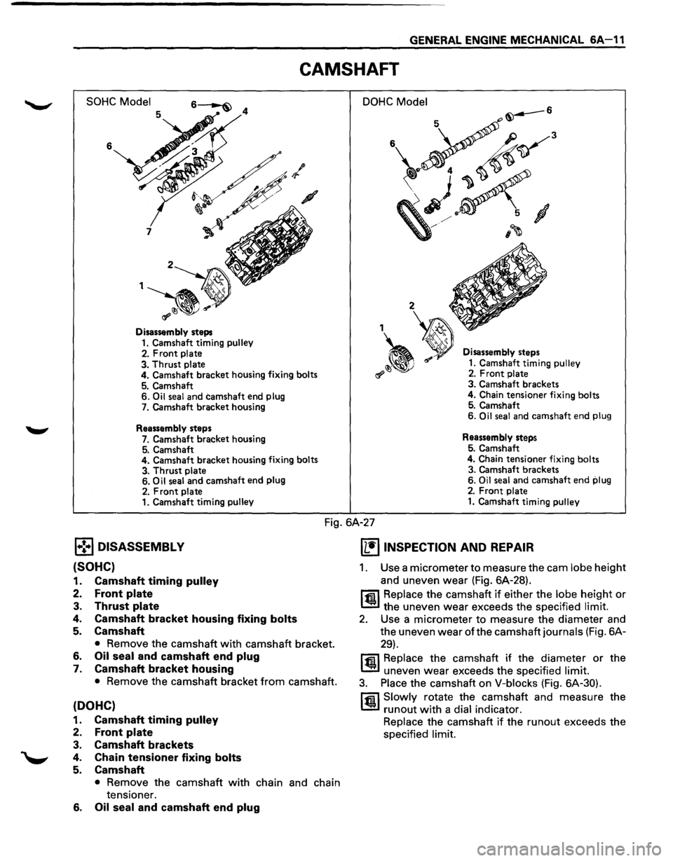
CAMSHAFT
SOHC Model
6 7
1
Disassembly steps
1. Camshaft timing pulley
2. Front plate
3. Thrust plate 4. Camshaft bracket housing fixing bolts
5. Camshaft 6. Oil seal and camshaft end plug
7. Camshaft bracket housing
Reassembly steps
7. Camshaft bracket housing 5. Camshaft
4. Camshaft bracket housing fixing bolts
3.
Thrust plate
6. Oil seal and camshaft end plug
2. Front plate 1. Camshaft timing pulley
DOHC Model
Disassembly steps
1. Camshaft timing pulley 2. Front plate
3. Camshaft brackets
4. Chain tensioner fixing bolts
5. Camshaft
6. Oil seal and camshaft end plug
Reassembly steps
5. Camshaft
4. Chain tensioner fixing bolts
3. Camshaft brackets
6.
Oil seal and camshaft end plug 2. Front plate
1. Camshaft timing pulley
Fig. 6A-27
1.-!•l DISASSEMBLY
(SOHC)
1. Camshaft timing pulley
2. Front plate
3. Thrust plate
4. Camshaft bracket housing fixing bolts
5. Camshaft
• Remove the camshaft with camshaft bracket.
6. Oil seal and camshaft end plug
7. Camshaft bracket housing
• Remove the camshaft bracket from camshaft.
(OOHC)
1. Camshaft timing pulley
2. Front plate
3. Camshaft brackets
4. Chain tensioner fixing bolts
5. Camshaft
• Remove the camshaft with chain and chain
tensioner.
6. Oil seal and camshaft end plug
IL•IINSPECTION AND REPAIR
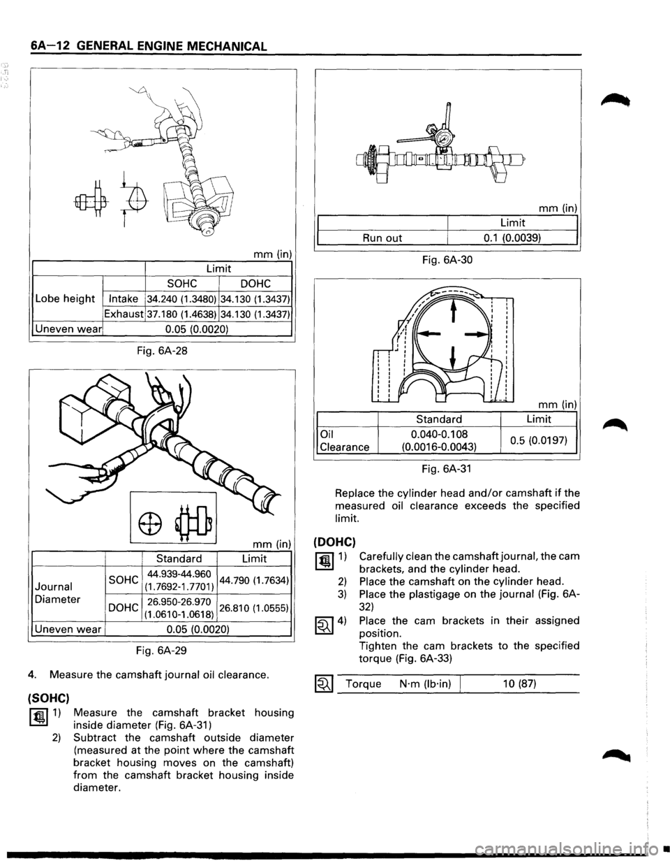
1. Use a micrometer to measure the cam lobe height
and uneven
wear (Fig. 6A-28).
Hffil Replace the camshaft if either the lobe height or
l..!:l the uneven wear exceeds the specified limit.
2. Use a micrometer to measure the diameter and
the uneven wear
of the camshaft journals (Fig. 6A-
29).
Hffil Replace the camshaft if the diameter or the
l..!:l uneven wear exceeds the specified limit.
3. Place the camshaft on V-blocks (Fig. 6A-30).
rfiil Slowly rotate the camshaft and measure the
l..!:l runout with a dial indicator.
Replace the camshaft if the runout exceeds the
specified
limit.
Page 528 of 1928
6A-12 GENERAL ENGINE MECHANICAL
mm (in)
Limit
SOHC DOHC
Lobe height Intake 34.240 (1.3480) 34.130 (1.3437)
Exhaust 37.180 (1.4638) 34.130 (1.3437)
Uneven wear 0.05 (0.0020)
Journal
Diameter
Uneven
wear
Fig. 6A-28
mm (in)
Standard Limit
44.939-44.960 SOHC (1.
7692 _
1 _7701) 44.790 (1.7634)
26.950-26.970 DOHC (1 _
0610 _
1 _
0618 )
26.810 (1.0555)
0.05 (0.0020)
Fig. 6A-29
4. Measure the camshaft journal oil clearance.
(SOHC)
~1) Measure the camshaft bracket housing
inside diameter (Fig. 6A-31)
2) Subtract the camshaft outside diameter
(measured at the
point where the camshaft
bracket housing moves on the camshaft)
from the camshaft bracket housing inside
diameter.
mm (in)
Limit
Run out 0.1 (0.0039)
Fig. 6A-30
mm (in)
Limit
Oil
Clearance
0.040-0.1 08
(0.0016-0.0043) 0.5
(0.0197)
Fig. 6A-31
Replace the cylinder head
and/or camshaft if the
measured oil clearance exceeds the specified
limit.
(DOHC)
~1) Carefully clean the camshaft journal, the cam
brackets, and the
cylinder head.
2) Place the camshaft on the cylinder head.
3) Place the plastigage on the journal (Fig. 6A-
32)
~4) Place the cam brackets in their assigned
position.
Tighten the cam brackets
to the specified
torque (Fig. 6A-33)
~~~ Torque N·m (lb·in) 10 (87)
•
Page 529 of 1928
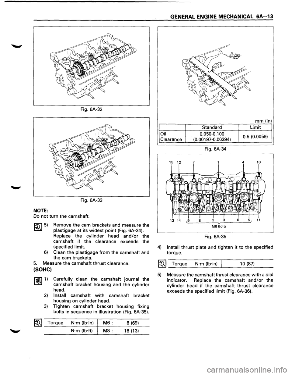
Fig. 6A-32
Fig. 6A-33
NOTE:
Do not turn the camshaft.
~~~5) Remove the cam brackets and measure the
plastigage at its widest point (Fig. 6A-34).
Replace the cylinder head and/or the
camshaft
if the clearance exceeds the
specified
limit.
6) Clean the plastigage from the camshaft and
the cam brackets.
5. Measure the camshaft thrust clearance.
(SOHC)
~1) Carefully clean the camshaft journal the
camshaft bracket housing and the
cylinder
head.
2) Install camshaft with camshaft bracket
housing on
cylinder head.
3) Tighten camshaft bracket housing fixing
bolts in sequence in illustration (Fig. 6A-35).
~~~ Torque N·m (lb·in)
N·m (lb·ft) M6:
M8:
8 (69)
18 (13)
GENERAL ENGINE MECHANICAL 6A-13
Oil
Clearance
15 12
Standard
0.050-0.100
(0.00197-0.00394)
Fig. 6A-34
7
mm (in)
Limit
0.5 (0.0059)
4 10
13 14 \-.:._9 __ 8 ___ 2 ---~_=.3 _ ___:6::__--=.5 1 11
M6 Bolts
Fig. 6A-35
4) Install thrust plate and tighten it to the specified
torque.
1~1 Torque N·m (lb·in) I 10 (87)
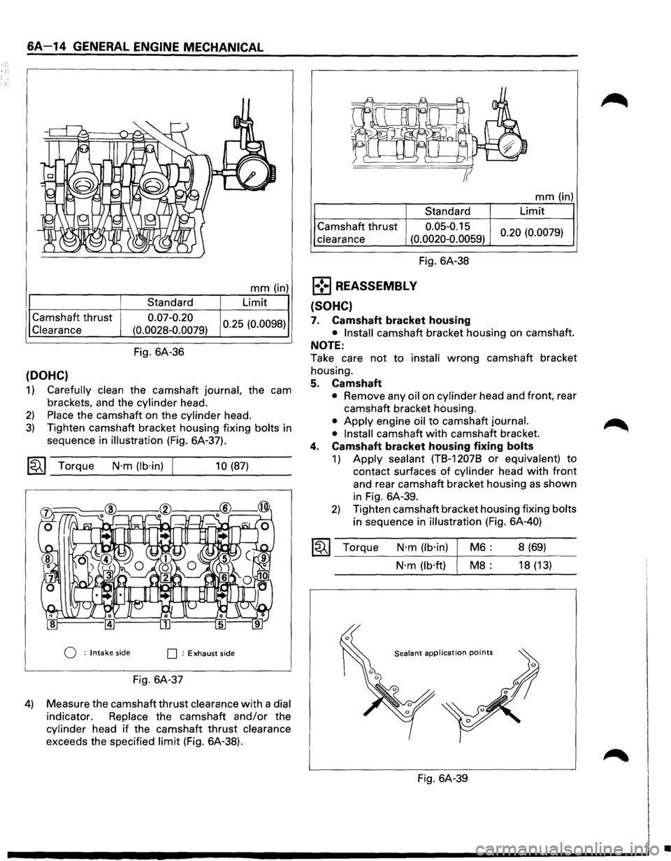
5) Measure the camshaft thrust clearance with a dial
indicator. Replace the camshaft and/or the
cylinder head if the camshaft thrust clearance
exceeds the specified limit (Fig. 6A-36).
Page 530 of 1928
6A-14 GENERAL ENGINE MECHANICAL
Camshaft thrust
Clearance
(DOHC}
Standard
0.07-0.20
(0.0028-0.0079)
Fig. 6A-36
mm (in)
Limit
0.25 (0.0098)
1) Carefully clean the camshaft journal, the cam
brackets, and the
cylinder head.
2) Place the camshaft on the cylinder head.
3) Tighten camshaft bracket housing fixing bolts in
sequence in
illustration (Fig. 6A-37).
~~~ Torque N·m (lb·in) 10 (87)
Q : Intake side O : Exhaust side
Fig. 6A-37
4) Measure the camshaft thrust clearance with a dial
indicator. Replace the camshaft and/or the
cylinder head if the camshaft thrust clearance
exceeds the specified limit (Fig. 6A-38).
mm (in)
Standard Limit
Camshaft thrust 0.05-0.15 0.20 (0.0079)
clearance (0.0020-0.0059)
l•!•l REASSEMBLY
(SOHC}
Fig. 6A-38
7. Camshaft bracket housing
• Install camshaft bracket housing on camshaft.
NOTE:
Take care not to install wrong camshaft bracket
housing.
5. Camshaft
• Remove any oil on cylinder head and front, rear
camshaft bracket housing.
• Apply engine oil to camshaft journal.
• Install
camshaft with camshaft bracket.
4. Camshaft bracket housing fixing bolts
1) Apply sealant (TB-12078 or equivalent) to
contact surfaces
of cylinder head with front
and rear camshaft bracket housing as shown
in Fig. 6A-39.
2) Tighten camshaft bracket housing fixing bolts
in sequence in illustration (Fig. 6A-40)
~~~ Torque N·m (lb·in)
N·m (lb·ft) M6:
M8:
Sealant application points
Fig. 6A-39 8
(69)
18 (13)
•
Page 531 of 1928
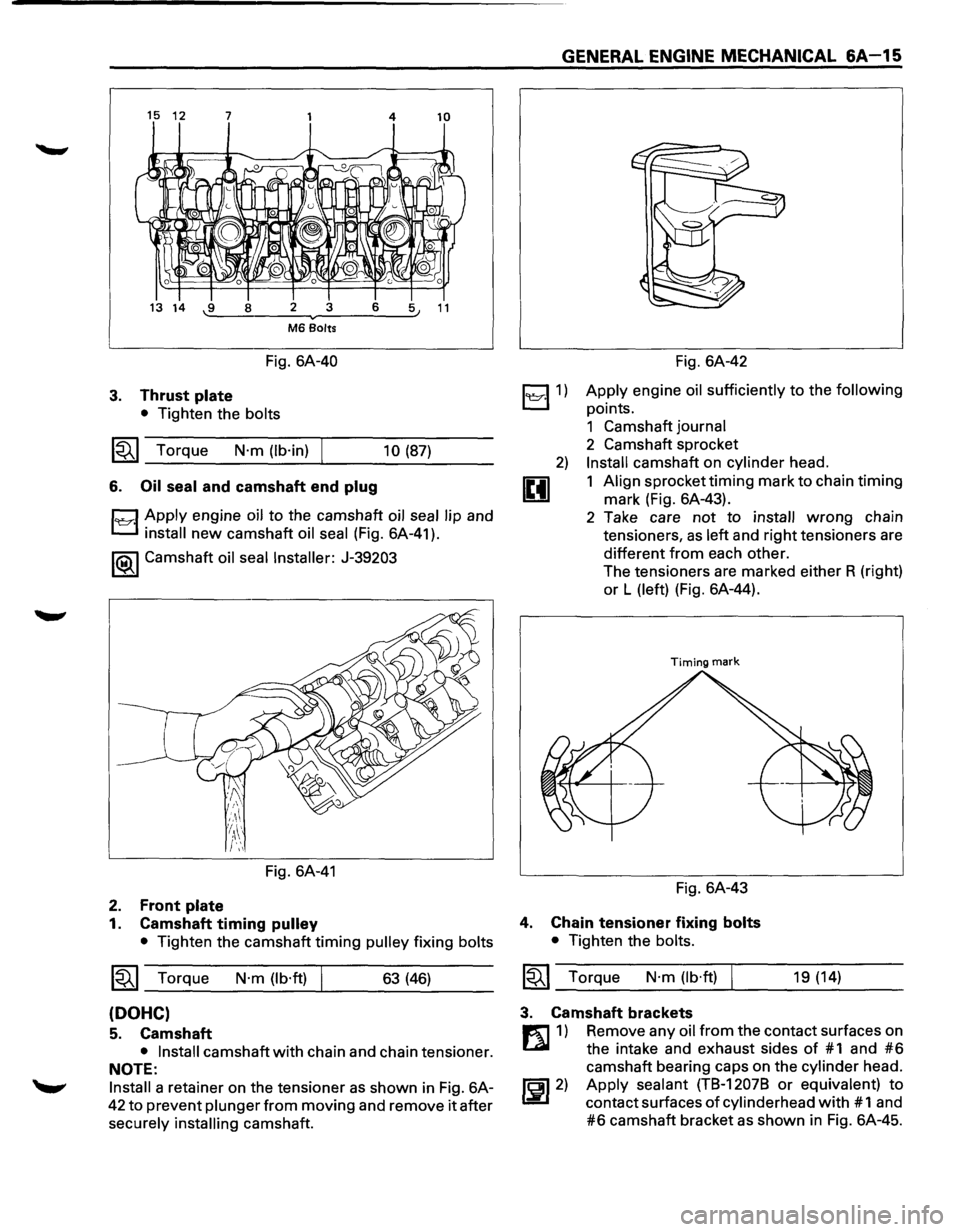
15 12 7 4 10
13 14 -.:9:...._--=8 __ =-2 ---..-....::3:.__ _ _:6:___:::..~5 11
M6 Bolts
Fig. 6A-40
3. Thrust plate
• Tighten the bolts
~~~ Torque N·m (lb·in) 10 (87)
6. Oil
seal and camshaft end plug
1~·1 Apply engine oil to the camshaft oil seal lip and
install new camshaft oil seal (Fig. 6A-41).
1®-1 Camshaft oil seal Installer: J-39203
Fig. 6A-41
2. Front plate
1. Camshaft timing pulley
• Tighten the camshaft timing pulley fixing bolts
1~1 Torque N·m (lb·ft) 63 (46)
(DOHC)
5. Camshaft
• Install camshaft with chain and chain tensioner.
NOTE:
Install a retainer on the tensioner as shown in Fig. 6A-
42 to prevent plunger from moving and remove it after
securely
installing camshaft.
GENERAL ENGINE MECHANICAL 6A-15
~1)
2)
u
Fig. 6A-42
Apply engine oil sufficiently to the following
points.
1 Camshaft journal
2 Camshaft sprocket
Install camshaft on cylinder head.
1 Align sprocket
timing mark to chain timing
mark (Fig. 6A-43).
2 Take care
not to install wrong chain
tensioners,
as left and right tensioners are
different from each other.
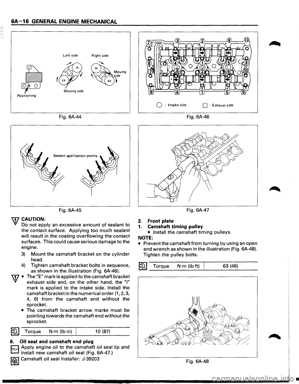
The tensioners are marked either R (right)
or L (left) (Fig. 6A-44).
Timing mark
Fig. 6A-43
4. Chain tensioner fixing bolts
• Tighten the bolts.
1~1 Torque N·m (lb·ft) 19 (14)
3. Camshaft brackets
m 1) Remove any oil from the contact surfaces on
Lll the intake and exhaust sides of #1 and #6
camshaft bearing caps on the cylinder head.
~~~2) Apply sealant (TB-12078 or equivalent) to
contact surfaces of cylinderhead with # 1 and
#6 camshaft bracket as shown in Fig. 6A-45.
Page 532 of 1928
6A-16 GENERAL ENGINE MECHANICAL
Left side Right side
Moving side Positioning
Q : Intake side 0 : Exhaust side
Fig. 6A-44 Fig. 6A-46
Sealant application points
Fig. 6A-45
7 CAUTION:
'VI Do not apply an excessive amount of sealant to
the contact surface. Applying too much sealant
will result
in the coating overflowing the contact
surfaces. This
could cause serious damage to the
engine.
3)
4)
w·
•
Mount the camshaft bracket on the cylinder
head.
Tighten camshaft bracket
bolts in sequence,
as shown in the illustration (Fig. 6A-46).
The
"E" mark is applied to the camshaft bracket
exhaust side and, on the other hand, the
"I"
mark is applied to the intake side. Install the
camshaft bracket in the
numerical order (1, 2, 3,
4, 6) from the camshaft end without the
sprocket.
The camshaft bracket
arrow marks must be
pointing towards the camshaft end
without the
sprocket.
~~~ Torque N·m (lb·in) f 10 (87)
6. Oil seal and camshaft end plug
CJ Apply engine oil to th~ camsh~ft oil seal lip and
L.::::J install new camshaft oil seal (F1g. 6A-47.)
1®..1 Camshaft oil seal Installer: J-39203
Fig. 6A-47
2. Front plate
1. Camshaft timing pulley
• Install
the camshaft timing pulleys.
NOTE:
• Prevent the camshaft from turning by using an open
end wrench
as shown in the illustration (Fig. 6A-48).
Tighten the
pulley bolts.
~~~ Torque N·m (lb·ft) 63 (46)
Fig. 6A-48
•
Page 533 of 1928
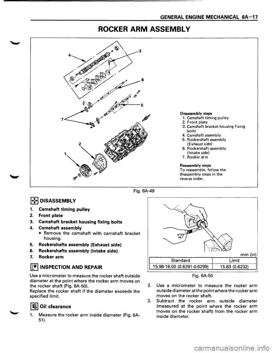
GENERAL ENGINE MECHANICAL 6A-17
ROCKER ARM ASSEMBL V
Disassembly steps 1. Camshaft timing pulley 2. Front plate 3. Camshaft bracket housing fixing
bolts 4. Camshaft assembly 5. Rockershaft assembly (Exhaust side)
6.
Rockershaft assembly
(Intake side)
7. Rocker arm
Reassembly steps To reassemble, follow the disassembly steps in the reverse order.
Fig. 6A-49
l•!•l DISASSEMBL V
1. Camshaft timing pulley
2. Front plate
3. Camshaft bracket housing fixing bolts
4. Camshaft assembly
• Remove the camshaft with camshaft bracket
housing.
5. Rockershafts assembly (Exhaust side)
6. Rockershafts assembly (Intake side)
7. Rocker arm
~ INSPECTION AND REPAIR
Use a micrometer to measure the rocker shaft outside
diameter at the point
where the rocker arm moves on
the rocker shaft (Fig.
6A-50).
Replace
the rocker shaft if the diameter exceeds the
specified
limit.
1~1 Oil clearance
1. Measure the rocker arm inside diameter (Fig. 6A-
51 ).
mm (in)
Standard Limit
15.98-16.00 (0.6291-0.6299) 15.83 (0.6232)
Fig. 6A-50
2. Use a micrometer to measure the rocker arm
outside diameter at the
point where the rocker arm
moves on the rocker shaft.
3. Subtract the rocker arm outside diameter
(measured at the point where the rocker arm
moves on the rocker shaft)
from the rocker arm
inside diameter.
Page 534 of 1928
6A-18 GENERAL ENGINE MECHANICAL
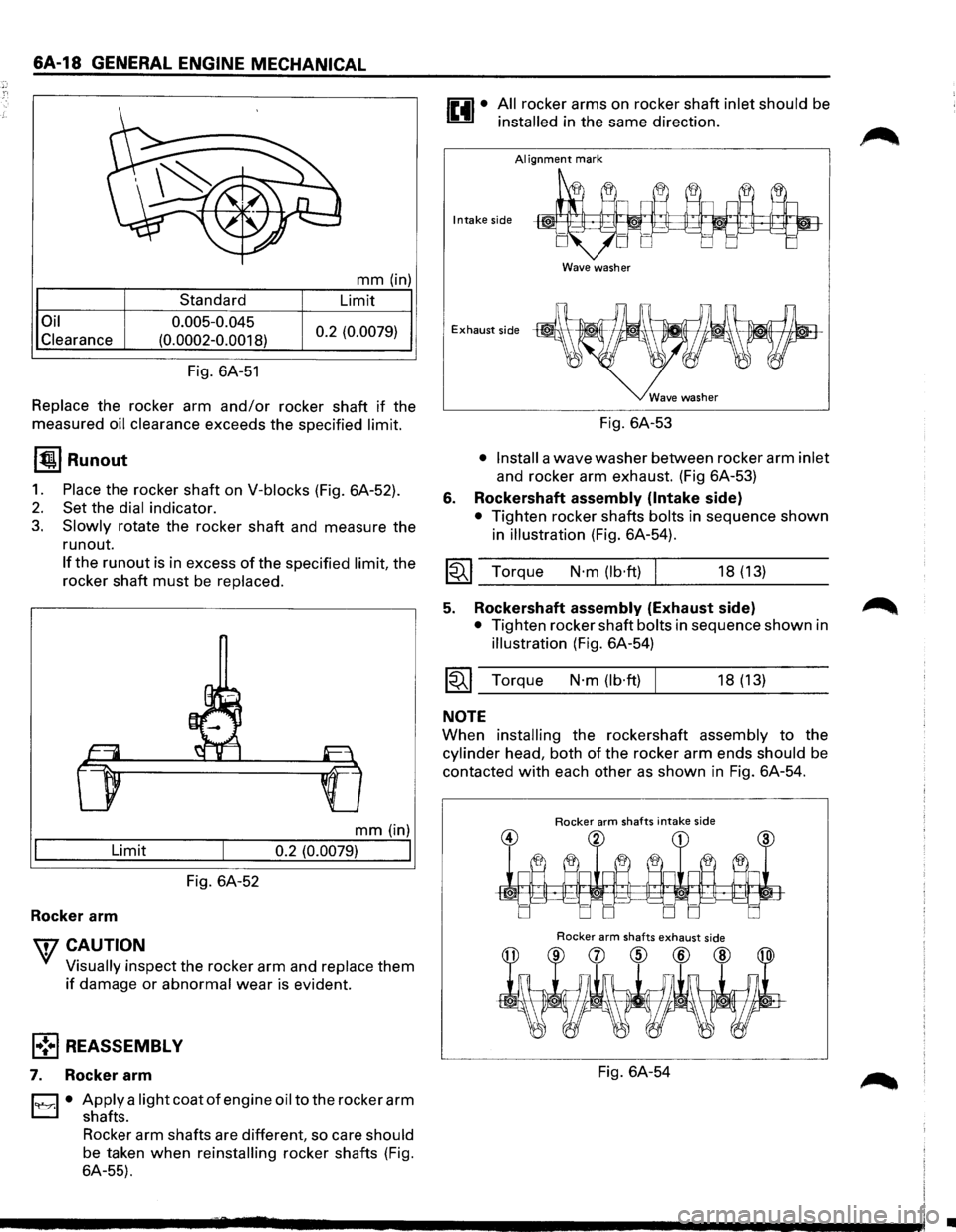
Oil
Clearance
Standard
0.005-0.045
(0.0002-0.0018)
Fig. 6A-51
mm (in)
Limit
0.2 (0.0079)
Replace the rocker arm and/or rocker shaft if the
measured
oil clearance exceeds the specified limit.
1~1 Runout
1. Place the rocker shaft on V-blocks (Fig. 6A-52).
2. Set the dial indicator.
3. Slowly rotate the rocker shaft and measure the
run out.
If the run out is in excess of the specified limit, the
rocker shaft
must be replaced.
mm (in)
Limit o.2 (o.oo79)
I
Fig. 6A-52
Rocker arm
wcAUTION
' Visually inspect the rocker arm and replace them
if damage or abnormal wear is evident.
l•!•l REASSEMBLY
7. Rocker arm
l'e::r.l • Apply a light coat of engine oil to the rocker arm
shafts.
Rocker arm shafts are different, so care
should
be taken when reinstalling rocker shafts (Fig.
6A-55).
All rocker arms on rocker shaft inlet should be
installed in the same direction.
AI ignment mark
Intake side
Wave washer
Exhaust side
6.
Fig. 6A-53
• Install a wave washer between rocker arm inlet
and rocker arm exhaust. (Fig 6A-53)
Rockershaft assembly (Intake side)
• Tighten rocker shafts bolts in sequence shown
in
illustration (Fig. 6A-54).
I~I __ To_r_q_ue ___ N_·_m_(_lb_·ft_)~l ______ 18_(_1_3) ____ _
5. Rockershaft assembly (Exhaust side) ~
• Tighten rocker shaft bolts in sequence shown in
illustration (Fig. 6A-54)
~~~ Torque N·m (lb·ft) I 18 (13)
NOTE
When installing the rockershaft assembly to the
cylinder head, both of the rocker arm ends should be
contacted
with each other as shown in Fig. 6A-54.
Rocker arm shafts intake side
Rocker arm shafts exhaust side
Fig. 6A-54
•