check engine ISUZU TROOPER 1995 Workshop Manual
[x] Cancel search | Manufacturer: ISUZU, Model Year: 1995, Model line: TROOPER, Model: ISUZU TROOPER 1995Pages: 1928
Page 787 of 1928
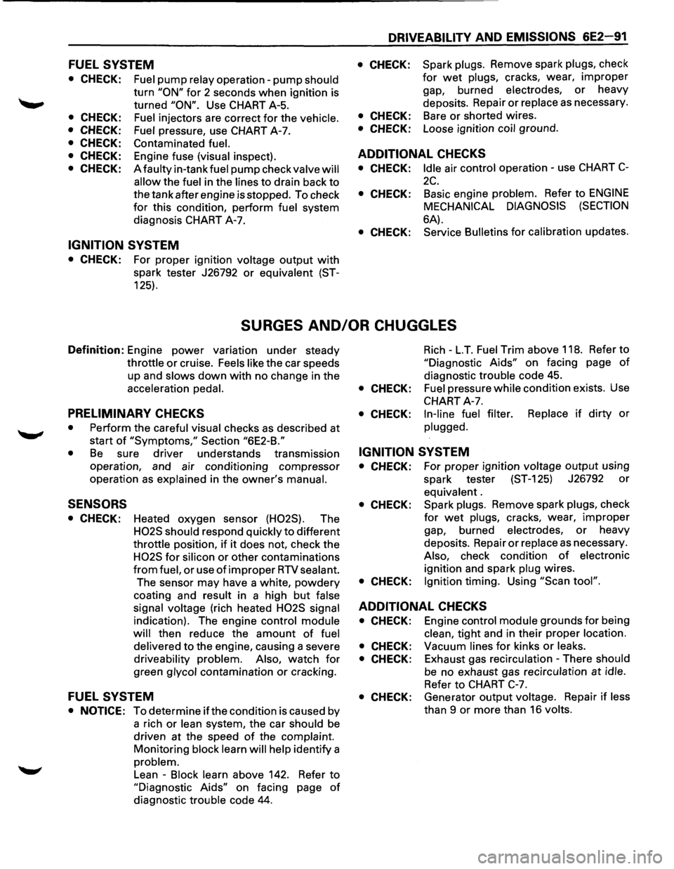
FUEL SYSTEM
• CHECK:
• CHECK:
• CHECK:
• CHECK:
• CHECK:
• CHECK:
Fuel pump relay operation-pump should
turn "ON" for 2 seconds when ignition is
turned
"ON". Use CHART A-5.
Fuel injectors are correct for the vehicle.
Fuel
pressure, use CHART A-7.
Contaminated
fuel.
Engine fuse (visual inspect).
A
faulty in-tank fuel pump check valve will
allow
the fuel in the lines to drain back to
the tank after engine is stopped. To check
for this condition, perform fuel system
diagnosis CHART A-7.
IGNITION SYSTEM
• CHECK: For proper ignition voltage output with
spark tester J26792 or equivalent (ST-
125).
DRIVEABILITY AND EMISSIONS 6E2-91
• CHECK: Spark plugs. Remove spark plugs, check
for wet plugs, cracks, wear, improper
gap, burned electrodes, or heavy
deposits. Repair
or replace as necessary.
• CHECK: Bare or shorted wires.
• CHECK: Loose ignition coil ground.
ADDITIONAL CHECKS
• CHECK: Idle air control operation-use CHART C-
2C.
• CHECK: Basic engine problem. Refer to ENGINE
MECHANICAL DIAGNOSIS (SECTION
6A).
• CHECK: Service Bulletins for calibration updates.
SURGES AND/OR CHUGGLES
Definition: Engine power variation under steady
throttle or cruise. Feels like the car speeds
up and
slows down with no change in the
acceleration pedal.
PRELIMINARY CHECKS
• Perform the careful visual checks as described at
start
of "Symptoms," Section "6E2-B."
•
Be sure driver understands transmission
operation, and air conditioning compressor
operation
as explained in the owner's manual.
SENSORS
• CHECK: Heated oxygen sensor (H02S). The
H02S should respond quickly to different
throttle position, if it does not, check the
H02S for silicon or other contaminations
from fuel, or use of improper RTV sealant.
The sensor may have a white, powdery
coating and result in a high but false
signal voltage
(rich heated H02S signal
indication). The engine control module
will
then reduce the amount of fuel
delivered
to the engine, causing a severe
driveability problem. Also, watch for
green glycol contamination or cracking.
FUEL SYSTEM
• NOTICE: To determine ifthe condition is caused by
a rich
or lean system, the car should be
driven at the speed of the complaint.
Monitoring block learn will help identify a
problem.
Lean -Block learn above 142. Refer to
"Diagnostic Aids" on facing page of
diagnostic trouble code 44.
Rich -L.T. Fuel Trim above 118. Refer to
"Diagnostic Aids" on facing page of
diagnostic trouble code 45.
• CHECK: Fuel pressure while condition exists. Use
CHART A-7.
• CHECK: In-line fuel filter. Replace if dirty or
plugged.
IGNITION SYSTEM
• CHECK: For proper ignition voltage output using
spark tester (ST-125) J26792
or
equivalent .
• CHECK: Spark plugs. Remove spark plugs, check
for wet plugs, cracks, wear, improper
gap, burned electrodes, or heavy
deposits. Repair
or replace as necessary.
Also, check condition of electronic
ignition and spark plug wires.
• CHECK: Ignition timing. Using "Scan tool".
ADDITIONAL CHECKS
• CHECK: Engine control module grounds for being
clean, tight and in their proper location.
• CHECK: Vacuum lines for kinks or leaks.
• CHECK: Exhaust gas recirculation -There should
be no exhaust gas recirculation at idle.
Refer to CHART C-7.
• CHECK: Generator output voltage. Repair if less
than 9 or more than 16 volts.
Page 788 of 1928
6E2-92 DRIVEABILITY AND EMISSIONS
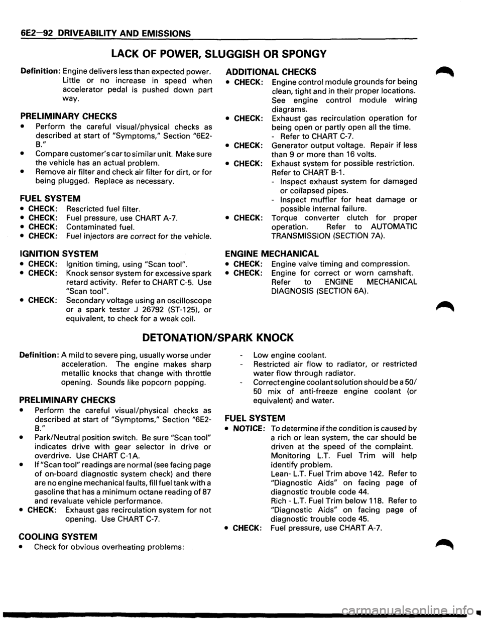
LACK OF POWER, SLUGGISH OR SPONGY
Definition: Engine delivers less than expected power.
Little or no increase in speed when
accelerator
pedal is pushed down part
way.
PRELIMINARY CHECKS
• Perform the careful visual/physical checks as
described at start of "Symptoms," Section "6E2-
B."
•
Compare customer's car to similar unit. Make sure
the
vehicle has an actual problem.
• Remove air filter and check air filter for dirt, or for
being plugged. Replace as necessary.
FUEL SYSTEM
• CHECK: Rescricted fuel filter.
• CHECK: Fuel pressure, use CHART A-7.
• CHECK: Contaminated fuel.
• CHECK: Fuel injectors are correct for the vehicle.
IGNITION SYSTEM
• CHECK: Ignition timing, using "Scan tool".
• CHECK: Knock sensor system for excessive spark
retard activity. Refer to CHART
C-5. Use
"Scan tool".
• CHECK: Secondary voltage using an oscilloscope
or a spark tester J 26792 (ST-125), or
equivalent, to check for a weak coil.
ADDITIONAL CHECKS
• CHECK: Engine control module grounds for being
clean,
tight and in their proper locations.
See engine control module wiring
diagrams.
• CHECK: Exhaust gas recirculation operation for
being open or partly open all the time.
- Refer to CHART
C-7.
• CHECK: Generator output voltage. Repair if less
than 9
or more than 16 volts.
• CHECK: Exhaust system for possible restriction.
Refer
to CHART B-1.
-Inspect exhaust system for damaged
or collapsed pipes.
-
Inspect muffler for heat damage or
possible internal failure.
• CHECK: Torque converter clutch for proper
operation. Refer
to AUTOMATIC
TRANSMISSION
(SECTION 7A).
ENGINE MECHANICAL
• CHECK: Engine valve timing and compression.
• CHECK: Engine for correct or worn camshaft.
Refer
to ENGINE MECHANICAL
DIAGNOSIS
(SECTION 6A).
DETONATION/SPARK KNOCK
Definition: A mild to severe ping, usually worse under
acceleration. The engine makes sharp
metallic knocks that change with throttle
opening.
Sounds like popcorn popping.
PRELIMINARY CHECKS
• Perform the careful visual/physical checks as
Low engine coolant.
Restricted air
flow to radiator, or restricted
water flow through radiator.
Correct engine
coolant solution should be a 50/
50 mix of anti-freeze engine coolant (or
equivalent) and water.
described at start
of "Symptoms," Section "6E2-FUEL SYSTEM
B."
•
Park/Neutral position switch. Be sure "Scan tool"
indicates drive with gear selector in drive or
overdrive. Use
CHART C-1A.
• If "Scan tool" readings are normal (see facing page
of on-board diagnostic system check) and there
are no engine mechanical faults,
fill fuel tank with a
gasoline
that has a minimum octane reading of 87
and revaluate vehicle performance.
• CHECK: Exhaust gas recirculation system for not
opening. Use CHART C-7.
COOLING SYSTEM
• Check for obvious overheating problems:
• NOTICE: To determine if the condition is caused by
a rich
or lean system, the car should be
driven at the speed
of the complaint.
Monitoring
LT. Fuel Trim will help
identify problem.
Lean-
LT. Fuel Trim above 142. Refer to
"Diagnostic Aids" on facing page of
diagnostic trouble code 44.
Rich-LT. Fuel Trim below 118. Refer to
"Diagnostic Aids" on facing page of
diagnostic trouble code 45.
• CHECK: Fuel pressure, use CHART A-7.
..
Page 789 of 1928
IGNITION SYSTEM
• CHECK: Spark plugs for proper heat cause. Refer
to Owner's Manual.
• CHECK: Ignition timing, using a "Scan tool".
ENGINE MECHANICAL
• CHECK: For excessive oil in the combustion
chamber. -
Valve oil seals for leaking.
• CHECK: Combustion chambers for excessive
carbon
build up. Remove carbon with top
engine cleaner and follow instructions on
can.
DRIVEABILITY AND EMISSIONS 6E2-93
• CHECK: Combustion chamber pressure by
performing a compression test.
See
ENGINE MECHANICAL DIAGNOSIS
(SECTION 6A).
• CHECK: For incorrect basic engine parts such as
cam, heads, pistons, etc.
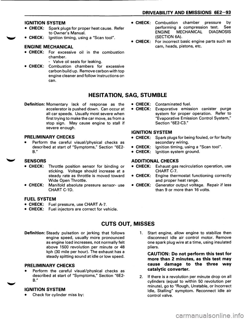
HESITATION, SAG, STUMBLE
Definition: Momentary lack of response as the
accelerator is pushed down. Can occur at
all car speeds. Usually most severe when
first trying
to make the car move, as from a
stop sign. May cause engine to
stall if
severe enough.
PRELIMINARY CHECKS
• Perform the careful visual/physical checks as
described at start of "Symptoms," Section "6E2-
B."
SENSORS
• CHECK: Throttle position sensor for binding or
sticking. Voltage should increase at a
steady
rate as throttle is moved toward
Wide Open Throttle.
• CHECK: Manifold absolute pressure sensor-use
CHART C-10.
FUEL SYSTEM
• CHECK: Fuel pressure, use CHART A-7.
• CHECK: Fuel injectors are correct for vehicle.
• CHECK: Contaminated fuel.
• CHECK: Evaporative emission canister purge
system
for proper operation. Refer to
"Evaporative Emission Control System,"
Section "6E2-C3."
IGNITION SYSTEM
• CHECK: Spark plugs for being fouled, or for faulty
secondary wiring.
• CHECK: Ignition timing, using a "Scan tool".
• CHECK: Ignition system ground.
ADDITIONAL CHECKS
• CHECK: Exhaust gas recirculation operation, use
CHART
C-7.
• CHECK: Engine thermostat functioning correctly
and proper heat range.
• CHECK: Generator output voltage. Repair if less
than 9 or more than 16 volts.
CUTS OUT, MISSES
Definition: Steady pulsation or jerking that follows
engine speed, usually more pronounced
as engine load increases, not normally felt
above 1500 revolution per minute or 48
kph
(30 mile per hour). The exhaust has a
steady spitting sound at
idle or low speed.
PRELIMINARY CHECKS
• Perform the careful visual/physical checks as
described at start of "Symptoms," Section "6E2-
B."
IGNITION SYSTEM
• Check for cylinder miss by:
1. Start engine, allow engine to stabilize then
disconnect
idle air control motor. Remove
one spark
plug wire at a time, using insulated
pliers.
CAUTION: Do not perform this test for
more than 2 minutes,
as this test may
cause damage to the three
way
catalytic converter.
2. If there is a revolution per minute drop on all
cylinders (equal
to within 50 revolution per
minute), go
to "Rough, Unstable, or Incorrect
Idle, Stalling"
symptom. Reconnect idle air
control valve.
Page 790 of 1928
6E2-94 DRIVEABILITY AND EMISSIONS
3. If there is no revolution per minute (rpm) drop
on one or more cylinders, or excessive
variation is drop, check
for spark on the
suspected
cylinder(s) using a shop
oscilloscope or with J 26792 (ST-125) spark
tester
or equivalent. If no spark, refer to
ENGINE ELECTRICAL (SECTION 6D) for
intermittent operation of miss. If there is a
spark, remove spark
plug(s) in these cylinders
and check for:
-
Insulator Cracks.
- Wear.
-
Improper Gap.
- Burned
Electrodes.
-Heavy Deposits.
• CHECK: Spark plug wires by connecting
ohmmeter to ends of each wire in
question.
If meter reads over 30,000
ohms, replace wire(s).
FUEL SYSTEM
• CHECK: Fuel system -Plugged fuel filter, low
pressure. Use CHART A-7.
• CHECK: Contaminated fuel.
• CHECK: Injector drivers. Disconnect all injector
harness connectors. Connect
J 34730-2
Injector Test Light or equivalent 6 volts
test light between the harness terminal,
of each injector connector and note light
while
cranking. If test light fails to blink at
any connector, it is a faulty injector drive
circuit harness, connector
or terminal.
ENGINE MECHANICAL
• CHECK: Compression. Perform compression
check on
questionable cylinder(s) found
above.
If compression is low, repair as
necessary. Refer to ENGINE
MECHANICAL DIAGNOSIS (SECTION
6A).
• CHECK: Engine parts. Remove cam covers.
Check
for broken valve springs, worn
camshaft lobes and valve timing. Repair
as necessary. See ENGINE MECHANICAL
DIAGNOSIS (SECTION
6A).
ADDITIONAL CHECKS
• CHECK: For electromagnetic interference (EMI).
A missing condition can be caused by EMI
on the reference circuit. EMI can usually
be detected by monitoring engine speed
with a "Scan tool". A sudden increase in
rpm
with little change in actual engine
speed change, indicates
EMI is present. If
the problem exists, check routing of
secondary wires, check distributor
ground circuit.
• CHECK: Intake and exhaust manifold passage for
casting
flash.
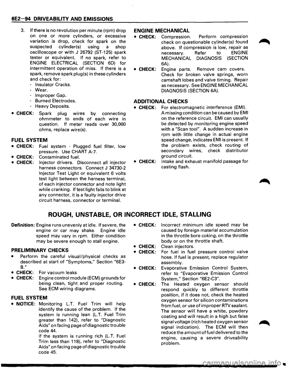
ROUGH, UNSTABLE, OR INCORRECT IDLE, STALLING
Definition: Engine runs unevenly at idle. If severe, the
engine
or car may shake. Engine idle
speed may vary in rpm. Either condition
may be severe enough to stall engine.
PRELIMINARY CHECKS
• Perform the careful visual/physical checks as
described at start
of "Symptoms," Section "6E3-
B."
• CHECK:
• CHECK:
For vacuum leaks
Engine control module (ECM) grounds for
being clean, tight and proper routing.
See ECM wiring diagrams.
FUEL SYSTEM
• NOTICE: Monitoring L.T. Fuel Trim will help
identify the cause of the problem. If the
system is running
lean (LT. Fuel Trim
greater than 142), refer
to "Diagnostic
Aids"
on facing page of diagnostic trouble
code 44.
If the system is running rich (L.T. Fuel
Trim less than 118), refer to "Diagnostic
Aids" on facing page of diagnostic trouble
code 45.
• CHECK:
• CHECK:
• CHECK:
• CHECK:
• CHECK:
Incorrect minimum idle speed may be
caused
by foreign material accumulation
in the throttle bore coking, on the throttle
body or on the throttle shaft.
Clean injectors.
For
fuel in fuel pressure control valve
hose. If fuel is present, replace regulator
assembly.
Evaporative Emission Control System,
refer to "Evaporative Emission Control
System," Section "6E2-C3".
The Heated oxygen sensor should
respond quickly to different throttle
position, if it does not, check the heated
oxygen sensor
for silicon contaminations
from fuel, or use of improper RTV sealant.
The sensor will have a white, powdery
coating and will result in a high but false
signal voltage
(rich heated oxygen sensor
signal indication). The ECM will then
reduce the
amount of fuel delivered to the
engine, causing a severe
driveability
problem.
II
Page 791 of 1928
IGNITION SYSTEM
• CHECK: Ignition timing, using a "Scan tool".
• CHECK: Ignition system; wires, plugs, electronic
ignition, etc.
ENGINE MECHANICAL
• CHECK: Perform a cylinder compression check.
See ENGINE MECHANICAL DIAGNOSIS
(SECTION 6).
• CHECK: For correct camshaft or weak valve
springs.
ADDITIONAL CHECKS
• CHECK: Manifold absolute pressure sensor.
Refer to
CHART C-10.
• CHECK: Throttle linkage for sticking or binding.
• CHECK: Park/neutral position switch circuit. See
CHART C-1A,
or use "Scan tool" and be
sure
tool indicates vehicle is in drive with
gear selector in drive or overdrive.
DRIVEABILITY AND EMISSIONS 6E2-95
• CHECK:
• CHECK:
• CHECK:
• CHECK:
• CHECK:
• CHECK:
Idle air control operation, use CHART C-
2C.
Exhaust gas recirculation valve. There
should be no exhaust gas recirculation at
idle. Refer to CHART C-7A.
Air conditioning (A/C) signal to engine
control module, "Scan tool" should
indicate A/C is being requested when
ever
A/C is selected. If problem exists
with A/C "ON," check A/C system
operation
CHART C-10.
Positive crankcase ventilation valve for
proper operation. Refer to "Positive
Crankcase Ventilation (PCV),"
Section
"6E2-C13."
For broken motor mounts.
Generator output
voltage. Repair if less
than 9 or more than 16 volts.
POOR FUEL ECONOMY
Definition: Fuel economy, as measured by an actual
road test, is noticeably lower than
expected.
Also, fuel economy is
noticeably lower than it was on this car at
one time,
as previously shown by an actual
road test.
PRELIMINARY CHECKS
• Perform the careful visual checks as described at
start
of "Symptoms," Section "6E2-B."
• Visually (physically)
check: Vacuum hoses for
splits, kinks, and proper connections as shown on
"Vehicle Emission Control Information" label.
• Check
owner's driving habits.
Is A/C "ON" full time (Defroster mode "ON")?
Are tires at correct pressure?
Are
excessively heavy loads being carried?
Is acceleration too much, too often?
• Check air cleaner filter for dirty or being plugged.
IGNITION SYSTEM
• CHECK: Ignition timing. Refer to "Vehicle
Emission Control Information" label.
• CHECK: Spark plugs. Remove spark plugs, check
for wet plugs, cracks, wear, improper
gap, burned electrodes, or heavy
deposits. Repair or
replace as necessary.
COOLING SYSTEM
• CHECK: Engine coolant level.
• CHECK: Engine thermostat for faulty part (always
open) or for wrong heat range. Refer to
ENGINE COOLING (SECTION 68).
ENGINE MECHANICAL
• CHECK: Compression. See ENGINE MECHANICAL
DIAGNOSIS
(SECTION 6A).
ADDITION CHECKS
• CHECK:
• CHECK:
• CHECK:
• CHECK:
• CHECK:
TCC operation (A/T). Use CHART C-8. A
"Scan tool" should indicate a revolution
per minute drop, when the TCC is
commanded
"ON".
For exhaust system restriction.
For proper
calibration of speedometer.
Induction system and crankcase for air
leaks.
Fuel
injectors are correct for the vehicle.
Page 792 of 1928
6E2-96 DRIVEABILITY AND EMISSIONS
EXCESSIVE EXHAUST EMISSIONS OR ODORS
Definition: Vehicle fails an emission test. Vehicle has
excessive
"rotten egg" smell. Excessive
odors
do not necessarily indicate
excessive emissions.
PRELIMINARY CHECKS
• Perform on-board diagnostic system check.
• IF EMISSION TEST shows excessive CO and
hydrocarbon check items which cause car to run
RICH (Long Term Fuel Trim less than 118), refer to
"Diagnostic Aids" on facing page of diagnostic
trouble code (DTC) 45.
• If EMISSION TEST shows excessive NOx, check
items which cause car
to run lean or too hot.
COOLING SYSTEM
• If the "Scan tool" indicates a very high engine
coolant temperature and the system is running
lean:
CHECK: Engine coolant level
CHECK: Engine thermostat for faulty part
(always open) or for wrong heat range. Refer
to
ENGINE COOLING (SECTION 68).
CHECK: Cooling fan operation.
FUEL SYSTEM
• NOTICE: If the system is running rich (L.T. Fuel
Trim near 118), refer to "Diagnostic Aids"
on facing page
of DTC 45.
-
If the system is running lean (L.T. Fuel
Trim near 142) refer to "Diagnostic
Aids" on facing page of DTC 44.
• CHECK: For properly installed fuel cap.
• CHECK: Fuel pressure. Use CHART A-7.
• CHECK: Canister for fuel loading. Refer to
"Evaporative Emission Control System,"
Section
"6E2-C3."
IGNITION SYSTEM
• CHECK: Ignition timing. Refer to "Vehicle
Emission Control Information" label.
• CHECK: Spark plugs, plug wires, and ignition
components. Refer to
ENGINE
ELECTRICAL (SECTION 6D).
ADDITIONAL CHECKS
• CHECK: For vacuum leaks.
• CHECK: Exhaust gas recirculation valve for not
opening. Use CHART C-7.
• CHECK: For lead contamination of three way
catalytic converter (look for the removal
of fuel filler neck restrictor).
• CHECK: Carbon build-up. Remove carbon with
top engine cleaner. Follow instructions
on can.
• CHECK: PCV valve for being plugged, stuck or
blocked PCV hose or fuel in the
crankcase.
BACKFIRE
Definition: Fuel ignites in intake manifold, or in
exhaust system, making
loud popping
noise.
PRELIMINARY CHECKS
• Perform the careful visual/physical checks as
described at start of "Symptoms," Section "6E2-
B."
IGNITION SYSTEM
• CHECK: Proper ignition coil output voltage with
spark tester J26792 or equivalent (ST-
125).
• CHECK: Spark plugs. Remove spark plugs, check
for
wet plugs, cracks, wear, improper
gap, burned
electrodes, or heavy
deposits. Repair
or replace as necessary.
• CHECK: Spark plug wires for crossfire, also
inspect electronic ignition, spark plug
wires, and proper routing of plug wires.
• CHECK: Ignition timing. Refer to "Vehicle
Emission Control Information" label.
• CHECK: If an intermittent condition exists in the
ignition system, see
"Ignition System/
IGNITION CONTROL," Section "6E2-C4"
or ENGINE ELECTRICAL (SECTION 6D).
ENGINE MECHANICAL
• CHECK: Compression- Look for sticking or leaking
valves.
• CHECK: Valve timing, refer to ENGINE
MECHANICAL DIAGNOSIS (SECTION
6A).
• CHECK: Intake and exhaust manifold passages for
casting
flash.
FUEL SYSTEM
• CHECK: Perform fuel system diagnosis check, see
CHART A-7.
Page 793 of 1928
DRIVEABILITV AND EMISSIONS 6E2-97
ADDITIONAL CHECKS • CHECK: Intake and exhaust manifold for casting
• CHECK: Exhaust gas recirculation (EGR) gasket flash.
for faulty or loose fit.
• CHECK: EGR operation for being open all the time.
Refer to
"EGR," CHART C-7.
DIESELING, RUN-ON
Definition: Engine continues to run after key is turned
"OFF", but runs very roughly. If engine
runs
smoothly, check ignition switch and
adjustment.
PRELIMINARY CHECKS
• Perform the careful visual/physical checks as
described at start of "Symptoms," Section "6E2-
B."
FUEL SYSTEM
• CHECK: Injectors for leaking. Refer to "Fuel
System Diagnosis" CHART A-7.
Page 794 of 1928
6E2-98 DRIVEABILITY AND EMISSIONS
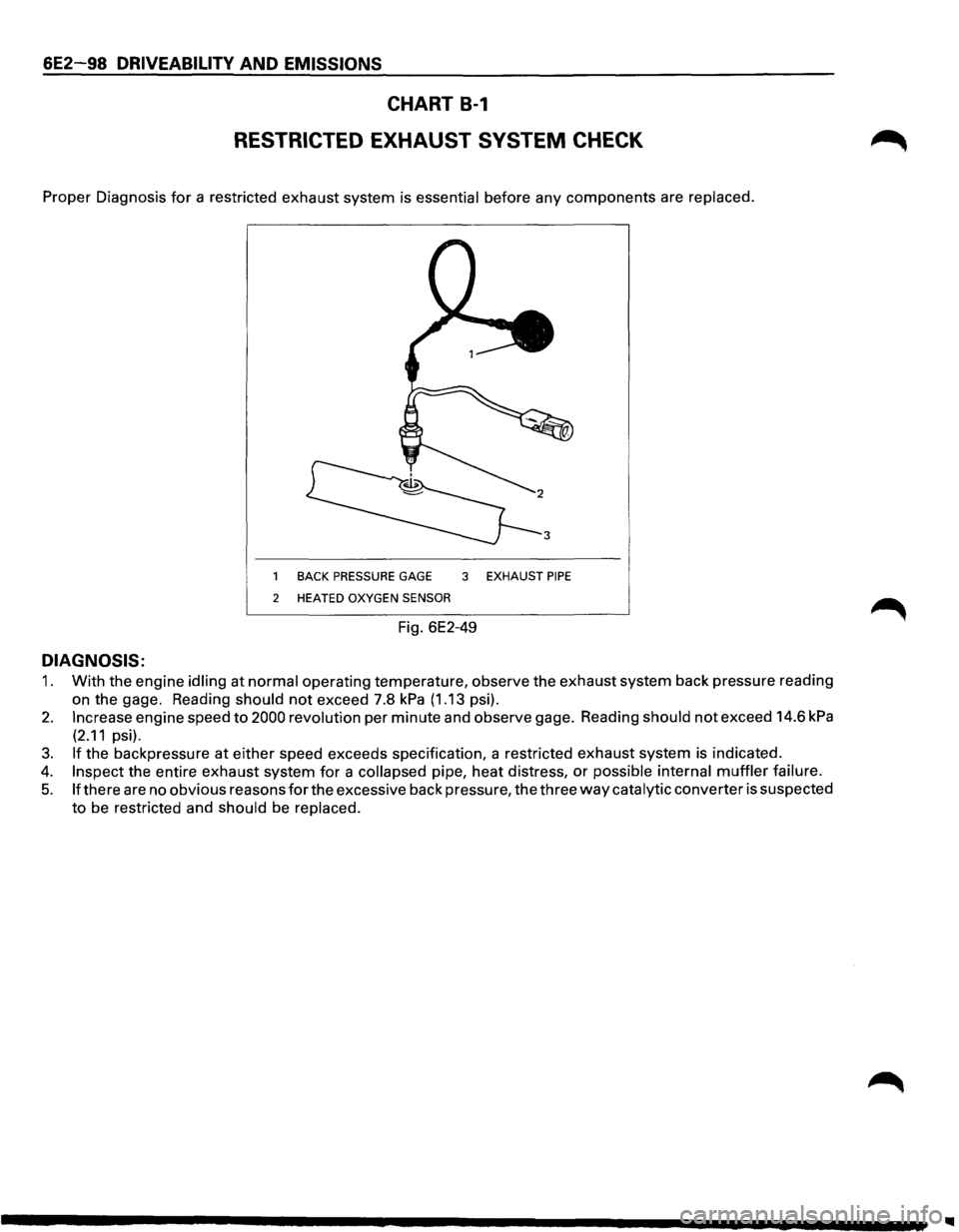
CHART 8-1
RESTRICTED EXHAUST SYSTEM CHECK
Proper Diagnosis for a restricted exhaust system is essential before any components are replaced.
BACK PRESSURE GAGE 3 EXHAUST PIPE
2 HEATED OXYGEN SENSOR
Fig. 6E2-49
DIAGNOSIS:
1. With the engine idling at normal operating temperature, observe the exhaust system back pressure reading
on the gage. Reading
should not exceed 7.8 kPa (1.13 psi).
2. Increase engine speed to 2000 revolution per minute and observe gage. Reading should not exceed 14.6 kPa
(2.11 psi).
3. If the backpressure at either speed exceeds specification, a restricted exhaust system is indicated.
4. Inspect the entire exhaust system for a collapsed pipe, heat distress, or possible internal muffler failure.
5. If there are no obvious reasons for the excessive back pressure, the three way catalytic converter is suspected
to be restricted and
should be replaced.
Page 795 of 1928
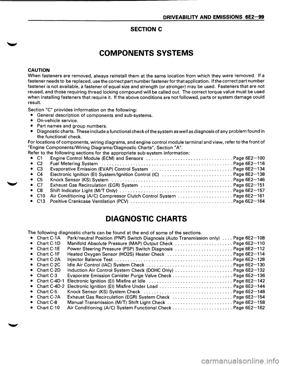
DRIVEABILITV AND EMISSIONS 6E2-99
SECTION C
COMPONENTS SYSTEMS
CAUTION
When fasteners are removed, always reinstall them at the same location from which they were removed. If a
fastener needs
to be replaced, use the correct part number fastener for that application. If the correct part number
fastener is not available, a fastener of equal size and strength (or stronger) may be used. Fasteners that are not
reused, and those requiring thread locking compound will be called out. The correct torque value must be used
when installing fasteners that require it. If the above conditions are not followed, parts or system damage could
result.
Section
"C" provides information on the following:
• General description of components and sub-systems.
• On-vehicle service.
• Part names and group numbers.
• Diagnostic charts. These include a functional check of the system as well as diagnosis of any problem found in
the functional check.
For locations
of components, wiring diagrams, and engine control module terminal and view, refer to the front of
"Engine Components/Wiring Diagrams/Diagnostic Charts", Section "A".
Refer to the following sections for the appropriate sub-system information:
• C1 Engine Control Module (ECM) and Sensors ................................. Page 6E2-1 00
•
C2 Fuel Metering System .................................................. Page 6E2-116
• C3 Evaporative Emission (EVAP) Control System ............................... Page 6E2-134
• C4 Electronic Ignition (EI) System/Ignition Control (IC) ........................... Page 6E2-138
• C5 Knock Sensor (KS) System .............................................. Page 6E2-146
• C7 Exhaust Gas Recirculation (EGR) System ................................... Page 6E2-151
• C8 Shift Indicator Light (M/T Only) ........................................... Page 6E2-157
• C1 0 Air Conditioning (A/C) Compressor Clutch Control System ..................... Page 6E2-161
• C13 Positive Crankcase Ventilation (PCV) ....................................... Page 6E2-164
DIAGNOSTIC CHARTS
The following diagnostic charts can be found at the end of some of the sections.
• Chart C-1A Park/neutral Position (PNP) Switch Diagnosis (Auto Transmission only) .... Page 6E2-108
• Chart C-1 D Manifold Absolute Pressure (MAP) Output Check ...................... Page 6E2-11 0
•
Chart C-1 E Power Steering Pressure (PSP) Switch Diagnosis ...................... Page 6E2-112
• Chart C-1 F Heated Oxygen Sensor (H02S) Heater Check ......................... Page 6E2-114
• Chart C-2A Injector Balance Test ............................................. Page 6E2-128
• Chart C-2C Idle Air Control (lAC) System Check ................................. Page 6E2-130
• Chart C-2D Induction Air Control System Check (DOHC Only) ...................... Page 6E2-132
• Chart C-3 Evaporate Emission Canister Purge Valve Check ....................... Page 6E2-136
• Chart C-4D-1 Electronic Ignition (EI) Misfire at Idle ................................ Page 6E2-142
• Chart C-4D-2 Electronic Ignition (EI) Misfire Under Load ............................ Page 6E2-144
• Chart C-5 Knock Sensor (KS) System Check .................................. Page 6E2-148
• Chart C-7A Exhaust Gas Recirculation (EGR) System Check ....................... Page 6E2-154
• Chart C-8 Manual Transmission (MIT) Shift Light Check ......................... Page 6E2-158
• Chart C-1 0 Air Conditioning (A/C) System Functional Check ....................... Page 6E2-162
Page 796 of 1928
6E2-100 DRIVEABILITY AND EMISSIONS
SECTION C1
ENGINE CONTROL MODULE (ECM) & SENSORS
CONTENTS
General Description ...................... 6E2-1 00
Engine Control Module (ECM) .............. 6E2-100
Engine Control Module (ECM) Function ....... 6E2-1 00
Information Sensors ..................... 6E2-1 01
Engine Coolant Temperature (ECT) Sensor ... 6E2-101
Intake Air Temperature (IAT) Sensor ........ 6E2-101
Heated Oxygen Sensor (H02S) ........... 6E2-101
Throttle Position
(TP) Sensor ............. 6E2-102
Manifold Absolute Pressure (MAP) Sensor ... 6E2-102
Vehicle Speed Sensor (VSS) ............. 6E2-102
Knock Sensor (KS) (DOHC ONLY) .......... 6E2-102
Air Conditioning (A/C) Request Signal ...... 6E2-1 02
Power Steering Pressure (PSP) Switch ...... 6E2-1 02
Park/Neutral Position (PNP) Switch
(Auto only)
........................ 6E2-1 03 Diagnosis ............................. 6E2-1 03
Engine Control Module (ECM) .............. 6E2-1 03
Electrically Erasable Programmable Read
Only Memory ........................ 6E2-1 03
Engine Control Module (ECM) Inputs ....... 6E2-103
Engine Coolant Temperature (ECT) Sensor ... 6E2-1 04
Intake Air Temperature (IAT) Sensor ........ 6E2-1 04
Heated Oxygen Sensor
(H02S) ........... 6E2-1 04
Throttle Position
(TP) Sensor ............. 6E2-1 04
Manifold Absolute Pressure (MAP) Sensor
... 6E2-1 04
Vehicle Speed Sensor (VSS) ............. 6E2-1 04
Air Conditioning (A/C) Request Signal
Power Steering Pressure
(PSP) Switch ..... .
Crankshaft Position
(CKP) Reference Signal ..
Park/Neutral Position (PNP) Switch ....... .
Knock Sensor
(KS) ................... .
On-Vehicle Service ..................... .
Engine Control Module
(ECM) ............ .
Engine Control Module
(ECM) Replacement ..
Engine Coolant Temperature (ECT) Sensor ... .
Intake Air Temperature (IAT) Sensor ........ .
Heated Oxygen Sensor
(H02S) ............ .
Throttle Position
(TP) Sensor ............. .
Manifold Absolute Pressure (MAP) Sensor
.... .
Vehicle Speed Sensor
(VSS) ............. .
Power Steering Pressure
(PSP) Switch ...... .
Park/Neutral Position
(PNP) Switch ......... .
Chart C-1A Park/Neutral Position
(PNP)
Switch Diagnosis .................... .
Chart
C-1 D Manifold Absolute Pressure (MAP)
Output Check
...................... .
Chart
C-1 E Power Steering Pressure (PSP)
Switch Diagnosis .................... .
Chart
C-1 F Heated Oxygen Sensor (H02S)
Heater Check ....................... .
6E2-104
6E2-104
6E2-104
6E2-104
6E2-104
6E2-104
6E2-104
6E2-105
6E2-105
6E2-106
6E2-106
6E2-107
6E2-107
6E2-107
6E2-107
6E2-107
6E2-108
6E2-110
6E2-112
6E2-114
GENERAL DESCRIPTION
ENGINE CONTROL MODULE (ECM)
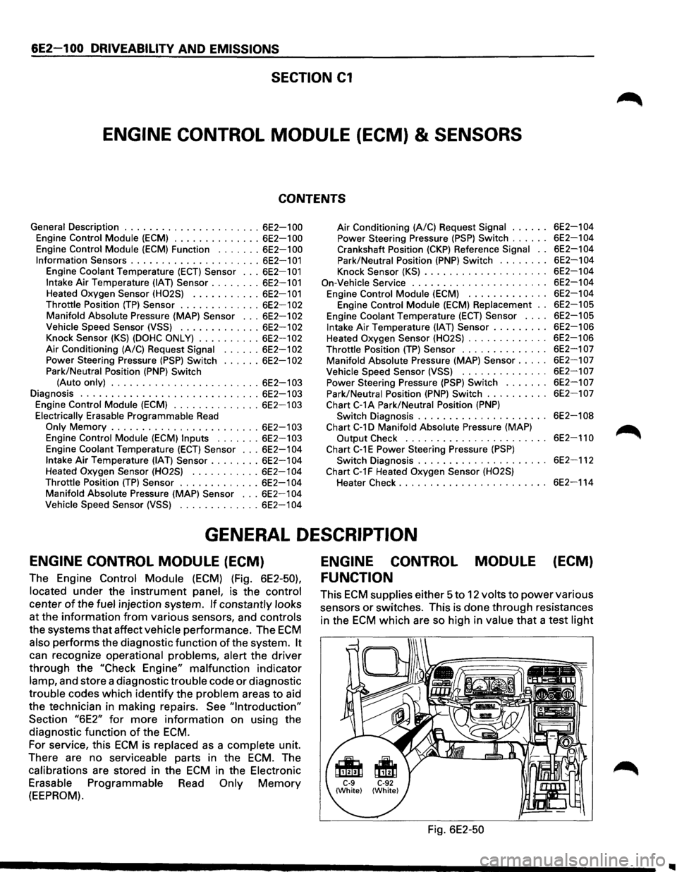
The Engine Control Module (ECM) (Fig. 6E2-50),
located under the instrument panel, is the control
center of the fuel injection system. If constantly looks
at the information from various sensors, and controls
the systems that affect vehicle performance. The ECM
also performs the diagnostic function of the system. It
can recognize operational problems, alert the driver
through the "Check Engine" malfunction indicator
lamp, and store a diagnostic trouble code or diagnostic
trouble codes which identify the problem areas to aid
the technician in making repairs.
See "Introduction"
Section "6E2" for more information on using the
diagnostic function
of the ECM.
For service, this ECM is replaced as a complete unit.
There are no serviceable parts in the
ECM. The
calibrations are stored in the
ECM in the Electronic
Erasable Programmable Read Only Memory
(EEPROM).
ENGINE CONTROL MODULE (ECM)
FUNCTION
This ECM supplies either 5 to 12 volts to power various
sensors
or switches. This is done through resistances
in the
ECM which are so high in value that a test light
Fig. 6E2-50