check engine ISUZU TROOPER 1995 Workshop Manual
[x] Cancel search | Manufacturer: ISUZU, Model Year: 1995, Model line: TROOPER, Model: ISUZU TROOPER 1995Pages: 1928
Page 797 of 1928
will not light when connected to the circuit. In some
cases, even an ordinary shop voltmeter
will not give an
accurate reading because its resistance is
too low.
Therefore, a 10 megohms input impedance digital
voltmeter is required to assure accurate voltage
readings.
The Engine
Control Module (ECM) controls output
circuits such as the fuel injectors, idle air control valve,
air conditioning clutch relay, etc. by controlling the
ground circuit through transistors
or a device called a
"quad-driver".
INFORMATION SENSORS
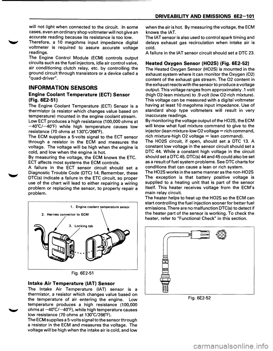
Engine Coolant Temperature (ECT) Sensor
(Fig. 6E2-51)
The Engine Coolant Temperature (ECT) Sensor is a
thermistor
(a resistor which changes value based on
temperature) mounted in the engine coolant stream.
Low ECT produces a high resistance (1 00,000 ohms at
-40.C/-40.F) while high temperature causes low
resistance (70 ohms at 130.C/266.F).
The ECM supplies a 5-volts signal to the ECT sensor
through a resistor in the
ECM and measures the
voltage. The voltage
will be high when the engine is
cold, and low when the engine is hot.
By measuring the voltage, the
ECM knows the ETC.
ECT affects most systems the ECM controls.
A failure in the
ECT sensor circuit should set a
Diagnostic Trouble Code
(DTC) 14. Remember, these
DTC(s) indicate a failure in the
ETC circuit, so proper
use
of the chart will lead to either repairing a wiring
problem or replacing the sensor, to properly repair a
problem.
1. Engine coolant temperature sensor
2. Harness connector to ECM
3. Locking tab
Fig. 6E2-51
Intake Air Temperature (IAT) Sensor
The Intake Air Temperature (IAT) sensor is a
thermistor, a resistor which changes
value based on
the temperature
of air entering the engine. Low
temperature produces a high resistance
(1 00,000
ohms at -4o·c/-40.F), while high temperature causes
low resistance (70 ohms at 130.C/266.F).
The ECM supplies a 5-volts signal to the sensor through
a resistor in the
ECM and measures the voltage. The
voltage
will be high when the intake air is cold, and low
DRIVEABILITV AND EMISSIONS 6E2-1 01
when the air is hot. By measuring the voltage, the ECM
knows the lAT.
The IAT sensor is also used to control spark timing and
delays exhaust gas recirculation when intake air is
cold.
A failure in the IAT sensor circuit should set a DTC 23.
Heated Oxygen Sensor (H02S) (Fig. 6E2-52)
The Heated Oxygen Sensor (H02S) is mounted in the
exhaust system where
it can monitor the Oxygen (02)
content of the exhaust gas stream. The 02 content in
the exhaust reacts
with the sensor to produce a voltage
output. This voltage ranges
from approximately .1 volt
(high 02-lean mixture) to .9 volt (low 02-rich mixture).
This voltage can
be measured with a digital voltmeter
having at
least 10 megohms input impedance. Use of
standard shop type voltmeters will result in very
inaccurate readings.
By monitoring the voltage
output ofthe H02S, the ECM
will know what fuel mixture command to give to the
injector
(lean mixture-low 02 voltage= rich command,
rich mixture-high
02 voltage= lean command).
The
H02S circuit, if open, should set a DTC 13. A
constant
low voltage in the sensor circuit should set a
DTC 44. While a constant high voltage in the circuit
should set a DTC 45. DTC(s) 44 and 45 could also be set
as a result of fuel system problems. See DTC charts for
conditions that can cause a lean or rich system.
The
H02S works in the same manner as the non-H02S
The exception is that battery positive voltage is
supplied to a heating unit that is part of the sensor
itself. This heater receives voltage
from the ECM's
main
relay circuit.
The heater
helps to heat up the H02S so the ECM can
start
controlling the fuel injection sooner for better fuel
emissions. There are no malfunction DTC(s) to detect if
the heater part of the sensor is working. To check the
heater, refer to "Functional
Check" in this section.
Fig. 6E2-52
~
\W
Page 799 of 1928
Park/Neutral Position (PNP) Switch (Auto Only)
The Park/Neutral position (PNP) switch indicates to the
Engine Control Module
(ECM) when the transmission
is in park, neutral
or drive. This information is used for
the exhaust gas recirculation, and the idle air control
valve operation.
NOTE:
• Vehicle
should not be driven with PNP switch
disconnected,
as idle quality will be affected and a
possible false diagnostic trouble code
(DTC) 24
(vehicle speed sensor).
DRIVEABILITY AND EMISSIONS 6E2-103
See DIAGNOSIS AND GENERAL SERVICE Section for
more information on the PNP switch. The PNP switch is
part
of the neutral/start and backup light switch
assembly mounted on the transmission.
See CHART C-
1 A for PNP switch check.
DIAGNOSIS
To read the DTC(s), use a "Scan tool" or ground the
diagnostic test terminal,
with the engine not running
and the ignition
"ON". The "Check Engine" malfunction
indicator lamp
will flash DTC 12 three times and then
flash each
DTC stored in memory three times. All
DTC(s) stored in memory will have been read when
DTC 12 is flashed again.
No new
DTC(s) can be stored when in the diagnostics
test mode (diagnostics lead grounded). This
eliminates confusion while the system is being
serviced.
To clear the
DTC(s) from memory:
• Ignition "OFF".
•
Disconnect main fuse located in the under hood
fuse/relay center near the battery.
Since the ECM can have a failure which may affect only
one circuit, following the diagnostic procedures in this
section
will determine which circuit has a problem and
where
it is.
If a diagnostic chart indicates thatthe ECM connections
or ECM is the cause of a problem, and the ECM is
replaced,
but does not correct the problem, one of the
following may be the reason.
• There is a problem with the ECM terminal
connections-The diagnostic chart will say ECM
connections or ECM. The terminals may have to
be removed from the connector in order to check
them properly.
• The ECM is not correct for the Vehicle-Ane
incorrect
ECM may cause a malfunction and may
set a DTC.
• The problem is intermittent -This means that
the problem is
not present at the time the system is
being checked.
In this case, refer to the
"Symptoms" portion of the manual and make a
careful physical inspection
of all portions of the
system involved.
• Shorted solenoid, relay coil, or harness
Solenoid and relays are turned "ON" and "OFF" by
the
ECM, using internal electronic switches called
"drivers".
Each driver is part of a group of four,
called "quad-drivers". Failure of one driver can
damage any other driver in the set. A
shorted solenoid, relay coil, or harness in a l-EFT
SHCI
computer will not damage the ECM, but will
cause the circuit and controlled component to be
inoperative. When the circuit fault is not present or
has been repaired, the "quad-driver" will again
operate in a normal manner due to its fault
protected design. If a fault has been repaired in a
circuit controlled by a "quad-driver", the original
ECM should be reinstalled and the circuit checked
for proper operation. ECM replacement will not be
necessary if the repaired circuit or component now
operates correctly.
J 34636 or BT-8405 testers or equivalent provide a fast,
accurate means
of checking for a shorted coil or a short
to battery positive voltage.
• The replacement ECM may be faulty-After the
ECM is replaced, the system should be re-checked
for proper operation. If the diagnostic chart again
indicates the
ECM is the problem, substitute a
known good
ECM. Although this is a rare
condition,
it could happen.
ENGINE CONTROL MODULE (ECM)
A faulty ECM will be determined in the diagnostic
charts.
ELECTRONICALL V ERASABLE
PROGRAMMABLE READ
ONL V MEMORY
A faulty electrically erasable programmable read only
memory, which is part of the ECM, will set a DTC 51.
ENGINE CONTROL MODULE (ECM)
INPUTS
All of the sensors and input switches can be diagnosed
by the use
of "Scan tool".
Following is a short description of how the sensors and
switches can be diagnosed by the use
"Scan tool". The
"Scan tool" can also be used to compare the values for
a normal running engine with the engine you're
diagnosing.
Page 800 of 1928
6E2-1 04 DRIVEABILITV AND EMISSIONS
Engine Coolant Temperature (ECT) Sensor
A "Scan tool" displays engine temperature in degrees
centigrade. After engine is started, the temperature
should rise steadily to about 90°C then stabilize when
thermostat opens. If the engine has not been run for
several hours (overnight), the engine coolant
temperature (ECT) and intake air temperature (IAT)
readings should be close to each other. A fault in the
ECT sensor circuit should set a diagnostic trouble code
(DTC) 14. The DTC charts also contain a chart to check
for sensor resistance values relative to temperature.
Intake Air Temperature (IAT) Sensor
A "Scan tool" displays temperature of the air entering
the engine and
should read close to ambient air
temperature when engine
is cold, and rise as under
hood temperature increases.
If the engine has not
been run for several hours (overnight), the IAT sensor
temperature and
ECT readings should be close to each
other. A
failure in the IAT sensor circuit should set a
DTC 23. The DTC charts also contain a chart to check
for sensor resistance values relative to temperature.
Heated Oxygen Sensor (H02S)
The "Scan tool" has several positions that will indicate
the state
of the exhaust gases, Oxygen voltage,
integrator, and block learn. See "Scan tool" position
information in
"Introduction", "Driveability and
Emission," in this section.
A
problem in the oxygen sensor circuit, or fuel system,
should set a DTC 13 (open circuit), DTC 44 (lean
indication)/DTC 45 (rich indication). Refer to
applicable chart, if any of these DTC(s) were stored in
memory.
Throttle Position (TP) Sensor
A "Scan tool" displays throttle position in volts. On 3.2L
engine, Throttle position
(TP) sensor voltage should
read below 0.85 volts, with throttle closed and ignition
"ON", or at idle. Voltage should increase at a steady
rate
as throttle is moved toward wide open throttle.
The Engine
Control Module (ECM) has the ability to
auto-zero the TP sensor voltage if it is below about 0.85
volts. This means that any voltage less than 0.85 volts
will
be determined by the ECM to be 0% throttle.
Some
"Scan tools" have the ability to read the throttle
angle and should read 0%, when the throttle is closed.
A failure in the TP sensor or circuit should set a DTC 21.
Manifold Absolute Pressure (MAP) Sensor
"Scan tool" displays manifold pressure in volts. Low
pressure (high vacuum) reads a
low voltage, while a
high pressure
(low vacuum) reads a high voltage. A
failure in the Manifold Absolute Pressure (MAP) sensor
circuit
should set a DTC 33 and using the chart will find
the cause
of the problem. A DTC 33 may be set if a
rough or unstable
idle exists. CHART C-1 D can also be
used
to check MAP sensor.
Vehicle Speed Sensor (VSS)
A "Scan tool" reading should closely match with
speedometer reading with drive wheels turning. A
failure in the vehicle speed sensor circuit should set a
DTC 24.
AIR CONDITIONING (A/C) Request Signal
When air conditioning in "ON", the "Scan tool" should
indicate air conditioning "ON".
See
"Air Conditioning Compressor Clutch Control
System",
Section "6E2-C1 0" for A/C electrical system
diagnosis.
Power Steering Pressure (PSP) Switch
A "Scan tool" should read "OFF" normally, and "ON"
with high pressure. This reading may vary with
different "Scan tools". Refer to CHART C-1 E for power
steering pressure switch diagnosis.
Crankshaft Position (CKP) Reference Signal
The ignition control module sends a signal to the ECM,
which is used to calculate proper spark advance and
fuel delivery. A "Scan tool" will read this signal and is
displayed in revolution per minute.
See "Electronic
Ignition System",
Section "6E2-C-4" for more
information on the ignition system (ignition control).
Park/Neutral Position (PNP) Switch
A "Scan tool" should read park/neutral position when
in park, or neutral, and R-D, L, when in drive or
overdrive. This reading may vary with different makes
of tools. Refer to CHART C-1 A for park/neutral position
switch diagnosis.
Knock Sensor (KS)
A "Scan tool" will indicate when the knock sensor
module signals the ECM that knock is present. See
"Knock
Sensor System," Section "6E2-C5" for further
information on the knock sensor system.
ON-VEHICLE SERVICE
ENGINE CONTROL MODULE (ECM)
The ECM is programmed from the factory and has no replaceable calibration chip.
•
Page 801 of 1928
wcAUTION:
' • When replacing the production Engine Control
Module
(ECM) with a service ECM (controller),
it is important to transfer the broadcast
diagnostic
trouble code and production ECM
number to the service ECM label. Please do not
record on ECM cover. This will allow positive
identification
of ECM parts throughout the
service
life of the vehicle.
DRIVEABILITV AND EMISSIONS 6E2-1 05
\fCAUTION:
' • To prevent internal ECM damage, the ignition
must be
"OFF" when disconnecting or
reconnecting power
to ECM (for example;
battery cable, ECM pigtail, ECM fuse, jumper
cables etc.)
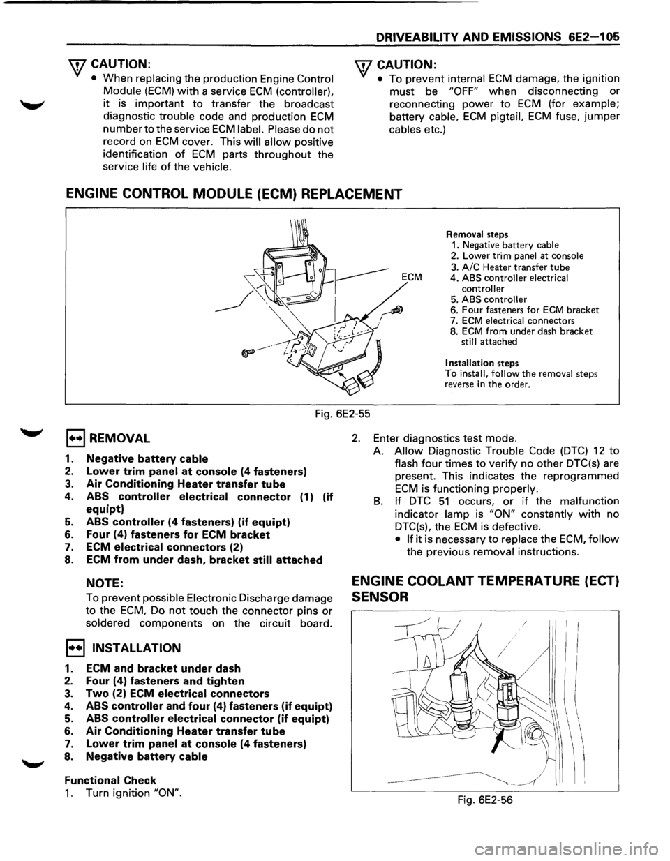
ENGINE CONTROL MODULE (ECM) REPLACEMENT
Removal steps 1. Negative battery cable 2. Lower trim panel at console
3. A/C Heater transfer tube ECM 4. ABS controller electrical
controller
5. ABS controller 6. Four fasteners for ECM bracket
7. ECM electrical connectors
8. ECM from under dash bracket still attached
Installation steps To install, follow the removal steps
reverse in the order.
Fig. 6E2-55
EJ REMOVAL
1. Negative battery cable
2. Lower trim panel at console (4 fasteners)
3. Air Conditioning Heater transfer tube
4. ABS controller electrical connector (1) (if
equipt)
5. ABS controller (4 fasteners) (if equipt)
6. Four (4) fasteners for ECM bracket
7. ECM
electrical connectors (2)
8. ECM from under dash, bracket
still attached
NOTE:
To prevent possible Electronic Discharge damage
to the ECM, Do not touch the connector pins or
soldered components on the circuit board.
I•+! INSTALLATION
1. ECM and bracket under dash
2. Four (4) fasteners and tighten
3. Two (2) ECM electrical connectors
4. ABS controller and four (4) fasteners (if equipt)
5. ABS controller electrical connector (if equipt)
6. Air Conditioning Heater transfer tube
7. Lower trim panel at console (4 fasteners)
8. Negative battery
cable
Functional
Check
1. Turn ignition "ON".
2. Enter diagnostics test mode.
A.
Allow Diagnostic Trouble Code (DTC) 12 to
flash four times to verify no other DTC(s) are
present. This indicates the reprogrammed
ECM is functioning properly.
B. If DTC 51 occurs, or if the malfunction
indicator lamp is "ON" constantly with no
DTC(s), the
ECM is defective.
• If it is necessary to replace the ECM, follow
the previous removal instructions.
ENGINE COOLANT TEMPERATURE (ECT)
SENSOR
Fig. 6E2-56
Page 803 of 1928
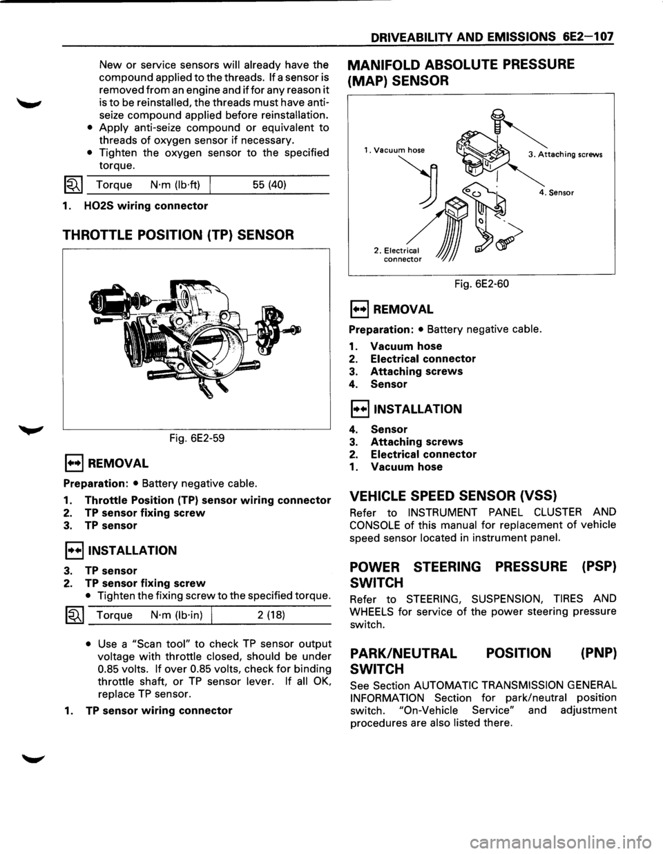
New or service sensors will already have the
compound
applied to the threads. If a sensor is
removed
from an engine and iffor any reason it
is to be reinstalled, the threads must have anti
seize compound
applied before reinstallation.
•
Apply anti-seize compound or equivalent to
threads of oxygen sensor if necessary.
• Tighten the oxygen sensor to the specified
torque.
1~1 Torque N·m (lb·ft) 55 (40)
1. H02S wiring connector
THROTTLE POSITION (TP) SENSOR
Fig. 6E2-59
E) REMOVAL
Preparation: • Battery negative cable.
1. Throttle Position (TP) sensor wiring connector
2. TP sensor fixing screw
3. TP sensor
I••IINSTALLATION
3. TP sensor
2. TP sensor fixing screw
• Tighten the fixing screw to the specified torque.
~~~ Torque N·m (lb·in) I 2 (18)
• Use a "Scan tool" to check TP sensor output
voltage with throttle closed, should be under
0.85 volts. If over 0.85 volts, check for binding
throttle shaft, or TP sensor lever. If all OK,
replace TP sensor.
1.
TP sensor wiring connector
DRIVEABILITY AND EMISSIONS 6E2-1 07
MANIFOLD ABSOLUTE PRESSURE
(MAP) SENSOR
1. Vacuum hose
) 0~
2 .• ,.~,,~,~
conne~ JJJ
4. Sensor
Fig. 6E2-60
E) REMOVAL
Preparation: • Battery negative cable.
1. Vacuum hose
2. Electrical connector
3. Attaching screws
4. Sensor
I••IINSTALLATION
4. Sensor
3. Attaching screws
2. Electrical connector
1. Vacuum hose
VEHICLE SPEED SENSOR (VSS)
Refer to INSTRUMENT PANEL CLUSTER AND
CONSOLE of this manual for replacement of vehicle
speed sensor located in instrument panel.
POWER STEERING PRESSURE (PSP)
SWITCH
Refer to STEERING, SUSPENSION, TIRES AND
WHEELS for service of the power steering pressure
switch.
PARK/NEUTRAL
SWITCH POSITION
(PNP}
See
Section AUTOMATIC TRANSMISSION GENERAL
INFORMATION Section for park/neutral position
switch.
"On-Vehicle Service" and adjustment
procedures are
also listed there.
Page 804 of 1928
6E2-1 08 DRIVEABILITV AND EMISSIONS
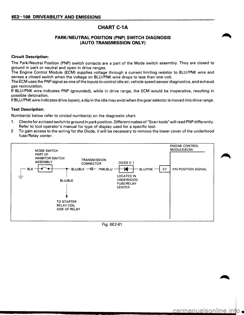
CHART C-1A
PARK/NEUTRAL POSITION (PNP} SWITCH DIAGNOSIS
(AUTO TRANSMISSION ONL
V}
Circuit Description:
The
Park/Neutral Position (PNP) switch contacts are a part of the Mode switch assembly. They are closed to
ground in park or neutral and open in drive ranges.
The Engine
Control Module (ECM) supplies voltage through a current limiting resistor to BLU/PNK wire and
senses a
closed switch when the voltage on BLU/PNK wire drops to less than one volt.
The ECM uses the PNP signal as one ofthe inputs to control idle air, vehicle speed sensor diagnostics, and exhaust
gas recirculation.
If BLU/PNK wire indicates PNP (grounded), while in drive range, the ECM would be inoperative, resulting in
possible detonation.
If BLU/PNK wire indicates drive (open), a dip in the idle may exist when the gear selector is moved into drive range.
Test Description:
Number(s)
below refer to circled number(s) on the diagnostic chart.
1. Checks for a closed switch to ground in park position. Different makes of "Scan tools" will read PNP differently.
Refer to tool operator's manual for type of display used for a specific tool.
2 To gain access to the wiring for the Diode, it will be necessary to remove the lower cover of the underhood
fuse/Relay center.
MODE SWITCH PART OF
INHIBITOR SWITCH TRANSMISSION ASSEMBLY CONNECTOR
_[ BLK +~•+1-------rt--BLU/BLK -{~ PNK/BLU
-BLU/BLK
l
TO STARTER
RELAY COIL
SIDE OF RELAY
DIODE E-1
ENGINE CONTROL MODULE(ECM)
~ BLU/PNK ~ P/N POSITION SIGNAL
LOCATED IN
UNDERHOOD
FUSE/RELAY
CENTER
Fig. 6E2-61
Ill
Page 806 of 1928
6E2-11 0 DRIVEABILITY AND EMISSIONS
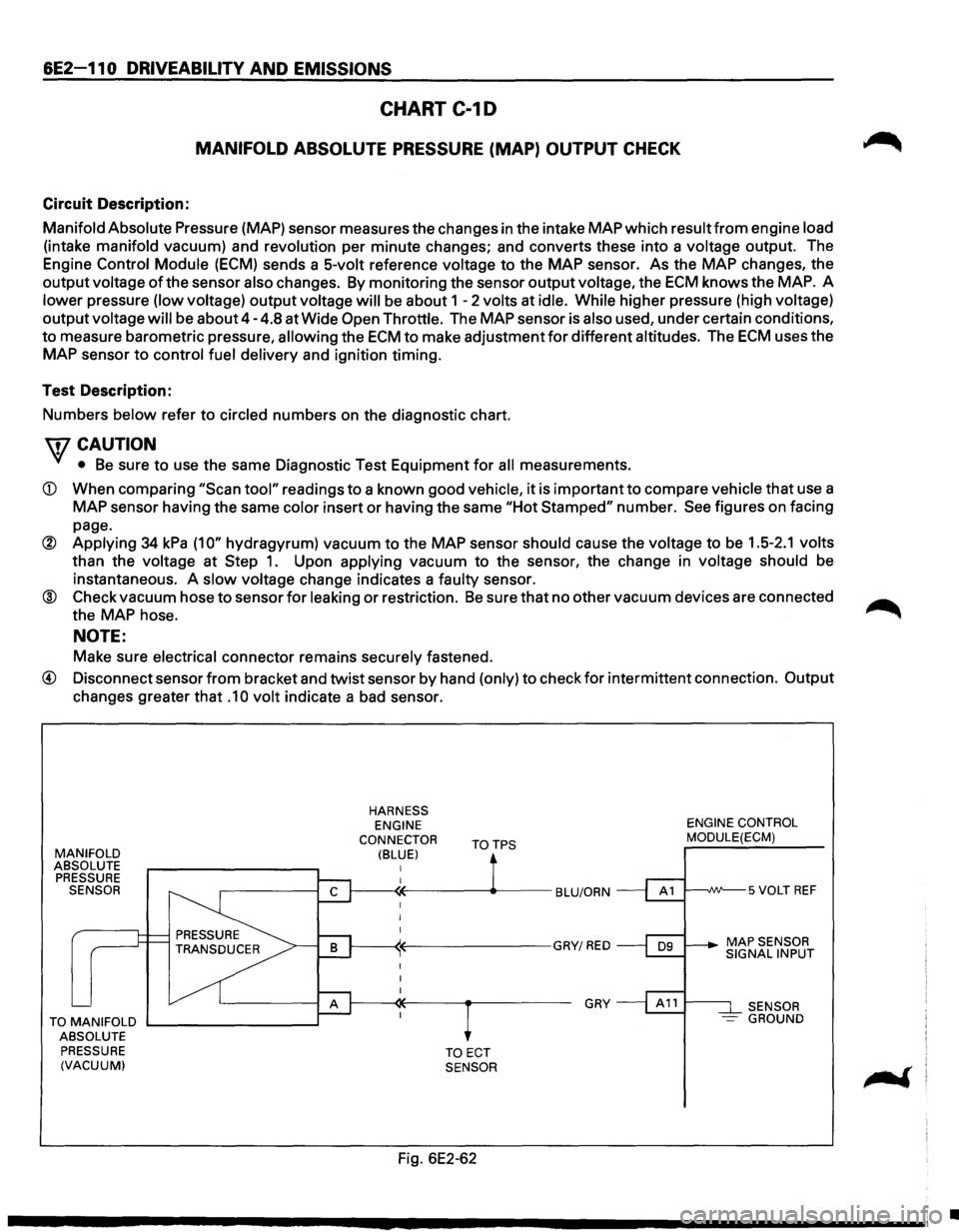
CHART C-10
MANIFOLD ABSOLUTE PRESSURE (MAP) OUTPUT CHECK
Circuit Description:
Manifold Absolute Pressure (MAP) sensor measures the changes in the intake MAP which result
from engine load
(intake manifold vacuum) and revolution per minute changes; and converts these into a voltage output. The
Engine
Control Module (ECM) sends a 5-volt reference voltage to the MAP sensor. As the MAP changes, the
output voltage of the sensor also changes. By monitoring the sensor output voltage, the ECM knows the MAP. A
lower pressure (low voltage)
output voltage will be about 1 - 2 volts at idle. While higher pressure (high voltage)
output voltage
will be about 4-4.8 at Wide Open Throttle. The MAP sensor is also used, under certain conditions,
to measure barometric pressure,
allowing the ECM to make adjustment for different altitudes. The ECM uses the
MAP sensor
to control fuel delivery and ignition timing.
Test Description:
Numbers
below refer to circled numbers on the diagnostic chart.
\fl CAUTION
'(/ • Be sure to use the same Diagnostic Test Equipment for all measurements.
CD When comparing "Scan tool" readings to a known good vehicle, it is important to compare vehicle that use a
MAP sensor having the same color insert
or having the same "Hot Stamped" number. See figures on facing
page.
® Applying 34 kPa (1 0" hydragyrum) vacuum to the MAP sensor should cause the voltage to be 1.5-2.1 volts
than the voltage at
Step 1. Upon applying vacuum to the sensor, the change in voltage should be
instantaneous. A slow voltage change indicates a faulty sensor.
® Check vacuum hose to sensor for leaking or restriction. Be sure that no other vacuum devices are connected ....-...
the MAP hose. ~
NOTE:
Make sure electrical connector remains securely fastened.
@) Disconnect sensor from bracket and twist sensor by hand (only) to check for intermittent connection. Output
changes greater that
.1 0 volt indicate a bad sensor.
MANIFOLD
ABSOLUTE PRESSURE
SENSOR
TO MANIFOLD
ABSOLUTE PRESSURE
(VACUUM)
HARNESS ENGINE
CONNECTOR
(BLUE) TOTPS
TOECT SENSOR
Fig. 6E2-62
GRY
ENGINE CONTROL
MODULE(ECM)
I---...JVV'--5 VOLT
REF
SENSOR -GROUND
•
Page 807 of 1928
DRIVEABILITV AND EMISSIONS 6E2-111
CHART C-10
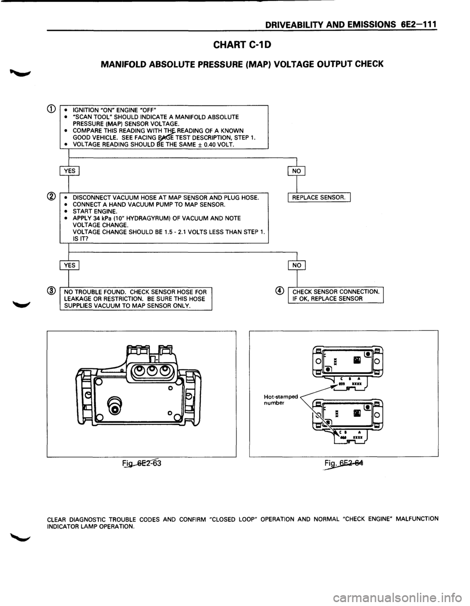
MANIFOLD ABSOLUTE PRESSURE (MAP) VOLTAGE OUTPUT CHECK
CD • IGNITION UON" ENGINE "OFF"
• uSCAN TOOL" SHOULD INDICATE A MANIFOLD ABSOLUTE
PRESSURE (MAP) SENSOR VOLTAGE. • COMPARE THIS READING WITii!TH READING OF A KNOWN
GOOD VEHICLE. SEE FACING E TEST DESCRIPTION, STEP 1. • VOLTAGE READING SHOULD E THE SAME± 0.40 VOLT.
® • DISCONNECT VACUUM HOSE AT MAP SENSOR AND PLUG HOSE.
• CONNECT A HAND VACUUM PUMP TO MAP SENSOR.
• START ENGINE.
•
APPLY 34 kPa (10" HYDRAGYRUM) OF VACUUM AND NOTE VOLTAGE CHANGE.
VOLTAGE CHANGE SHOULD BE 1.5-2.1 VOLTS LESS THAN STEP 1. IS IT?
@ NO TROUBLE FOUND. CHECK SENSOR HOSE FOR LEAKAGE OR RESTRICTION. BE SURE THIS HOSE
SUPPLIES VACUUM TO MAP SENSOR ONLY.
~3
@ CHECK SENSOR CONNECTION. IF OK, REPLACE SENSOR
Hot-stamped number
CLEAR DIAGNOSTIC TROUBLE CODES AND CONFIRM "CLOSED LOOP" OPERATION AND NORMAL "CHECK ENGINE" MALFUNCTION
INDICATOR LAMP OPERATION.
Page 808 of 1928
6E2-112 DRIVEABILITY AND EMISSIONS
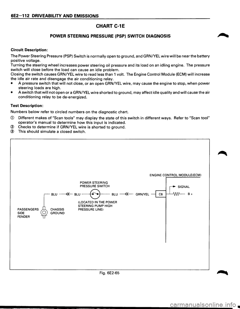
CHART C-1E
POWER STEERING PRESSURE (PSP) SWITCH DIAGNOSIS
Circuit Description:
The Power Steering Pressure
(PSP) Switch is normally open to ground, and GRNIYEL wire will be near the battery
positive
voltage.
Turning the steering wheel increases power steering oil pressure and its load on an idling engine. The pressure
switch
will close before the load can cause an idle problem.
Closing
the switch causes GRN/YEL wire to read less than 1 volt. The Engine Control Module (ECM) will increase
the
idle air rate and disengage the air conditioning relay.
•
A pressure switch that will not close, or an open GRNIYEL wire, may cause the engine to stop, when power
steering loads are high.
• A switch that will not open or a GRNIYEL wire shorted to ground, may affect idle quality and will cause the air
conditioning
relay to be de-energized.
Test Description:
Numbers
below refer to circled numbers on the diagnostic chart.
CD Different makes of "Scan tools" may display the state of this switch in different ways. Refer to "Scan tool"
operator's manual to determine how this input is indicated.
® Checks to determine if GRNIYEL wire is shorted to ground.
@ This should simulate a closed switch.
POWER STEERING PRESSURE SWITCH ENGINE
CONTROL
MODULE(ECM)
I SIGNAL
r
BLU ---(~ BLU --+8 .. •f---BLU --{~ GRN/YEL ~ ~ B +
(LOCATED IN THE POWER
STEERING PUMP HIGH PASSENGERS CHASSIS PRESSURE LINE)
SIDE GROUND
FENDER
Fig. 6E2-65
•
Page 809 of 1928
DRIVEABILITY AND EMISSIONS 6E2-113
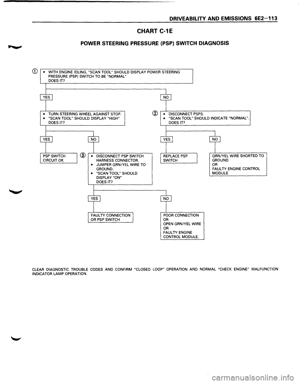
CHART C-1E
POWER STEERING PRESSUR,.E (PSP) SWITCH DIAGNOSIS
CD • WITH ENGINE IDLING, "SCAN TOOL" SHOULD DISPLAY POWER STEERING PRESSURE (PSP) SWITCH TO BE "NORMAL" DOES IT?
•
TURN STEERING WHEEL AGAINST STOP. ® • DISCONNECT PSPS. • "SCAN TOOL" SHOULD DISPLAY "HIGH"
DOES IT? • "SCAN TOOL" SHOULD INDICATE "NORMAL".
@ • DISCONNECT PSP SWITCH HARNESS CONNECTOR.
• JUMPER GRNIYEL WIRE TO GROUND. • "SCAN TOOL" SHOULD DISPLAY "ON" DOES IT? DOES
IT?
POOR CONNECTION OR OPEN GRN/YEL WIRE OR FAULTY ENGINE
CONTROL MODULE. GRN/YEL
WIRE SHORTED TO GROUND OR FAULTY ENGINE
CONTROL MODULE
CLEAR
DIAGNOSTIC TROUBLE CODES AND CONFIRM "CLOSED LOOP" OPERATION AND NORMAL "CHECK ENGINE" MALFUNCTION
INDICATOR LAMP OPERATION.