fuel ISUZU TROOPER 1995 Workshop Manual
[x] Cancel search | Manufacturer: ISUZU, Model Year: 1995, Model line: TROOPER, Model: ISUZU TROOPER 1995Pages: 1928
Page 864 of 1928
6F-2 ENGINE EXHAUST (V6 3.2L)
When inspecting or replacing exhaust system
components, make sure there is adequate
clearance
from all points on the underbody to prevent over
heating the
floor pan and possible damage to the
passenger
compartment insulation and trim materials.
Check complete exhaust system and nearby body
areas and rear compartment lid for broken, damaged,
missing
or mispositioned parts, open seams, holes,
loose
connections or other deterioration which could
permit exhaust fumes to seep into the rear
compartment or passenger compartment. Dust or
water in the rear compartment may be an indication of
a problem in one of these areas. Any faulty areas
should be corrected immediately.
HANGERS
Various types of hangers are used to support exhaust
system(s). These
include conventional rubber straps,
rubber rings, and rubber
blocks.
The installation of exhaust system supports is very
important,
as improperly installed supports can cause
annoying vibrations
which can be difficult to diagnose.
THREE WAY CATAL VTIC CONVERTER
The three way catalytic converter is an emission
control device added to the exhaust system to reduce
pollutants from the exhaust gas stream.
W CAUTION:
VI • The catalytic converter requires the use of
unleaded fuel only.
Periodic
maintenance of the exhaust system is not
required. If the vehicle is raised for other service, it is
advisable to check the condition of the complete
exhaust system.
A
dual bed monolith catalytic converter is used in
combination
with three way catalytic converter.
Catalytic Types:
Three
way (Reduction/Oxidation) catalyst
The catalyst coating on the three way (reduction)
converter contains
platinum and rhodium which
lowers the levels of oxide of nitrogen (NOx) as well as
hydrocarbons (HC) and carbon monoxide (Co).
GASKET
The gasket must be replaced whenever a new exhaust
pipe,
muffler or catalytic converter is installed.
Page 874 of 1928
7A-2 AUTOMATIC TRANSMISSION (4L30-E)
Valve Body Assembly (Adapter Case) ....... 7A-168 Third Clutch and Sprag Unit ....................... 7A-195
Transmission Control
Module (TCM) ......... 7A-169 Third Clutch .................................................. 7A-196
Speed Sensor (Extension Housing) ............ 7A-169 Sprag
Unit ....................................................
7A-198
Transmission
Oil Temperature Sensor Second
Clutch .............................................. 7A-199
(Adapter Case) ..........................................
7A-170 3-4 Accumulator Piston ............................... 7A-200
Front Oil Seal (Converter Housing) ............ 7A-170 Reverse Clutch Piston and Center
Rear
Oil Seal (Extension Housing) ............. 7A-171 Support ..................................................... 7 A-202
Unit Repair ........................................................ 7A-173 Overrun Clutch and Turbine Shaft ............. 7A-204
Transmission (4L30-E) ................................. 7A-173 Main Data and Specifications ......................... 7 A-207
Converter Housing and Oil Pump General
Specifications ................................. 7 A-207
Assembly .................................................. 7 A-189 Torque
Specifications .................................. 7A-208
Oil
Pump ....................................................... 7A-190 Special Tools .................................................... 7A-211
Main Case Valve Body ................................. 7A-191 4L30-E Parts List.. ............................................. 7A-213
Adapter Case Valve Body ............................ 7A-193 Hydraulic
Circuit Diagram .......... End of This Manual
GENERAL DESCRIPTION
The 4L30-E is a 4-speed fully-automatic transmission.
It uses a microcomputer as a control unit to judge
running conditions
including throttle opening rate
and vehicle speed, then
it sets the shifting point in
the
optimum timing so that best driving performance
can be achieved.
In addition, the built-in shift mode select function can
select three shift modes according to the driver's
preference.
• Normal mode-Normal shift pattern.
• Winter mode-Starts in 3rd gear to reduce
slippage on ice
or snow.
• Power mode has a delayed upshift for when
more powerful acceleration is required.
Also, the built-in fail-safe
function ("backup mode")
assures driving performance even if the vehicle
speed sensor,
throttle signal or any solenoid fails.
Further, the self-diagnostic
function conducts diag
nosis in a short time when the control system fails,
thus improving serviceability.
The major features of 4L30-E are as follows:
• A compact structure consisting of 2 sets of
planetary gears and flat torque converter.
• Electronic control selects the optimum shift
mode according
to the driving conditions.
• Electronic control maintains the optimum hy
draulic pressure for clutch, band brake as well as
transmission so that shift feeling is improved.
• Two sets of planetary gears reduce friction of
power train.
Also, a lock-up mechanism in the torque con
verter reduces fuel consumption.
• Wide gear ratio and high torque rate of torque
converter provide
excellent starting perform
ance.
MODEL YEAR 1994-95 CHANGES
The Transmission Control Module (TCM) for ISUZU
TROOPER
models equipped with 4L30-E is changed
from "BOSCH" to "DELCO ELECTRONICS"
manufacture.
The main differences
which will be encountered
while servicing concerned vehicles are as follows:
Diagnostic Trouble Codes (DTC):
DTC's are changed: For example, DTC for
transmission gear error will be as follows depending
on the TCM unit:
-
On the "DELCO" unit (1994-95) ......... DTC 61
-On the "BOSCH" unit (1993-prior) ..... DTC 41
TCM Pin Connector:
The pin connector is changed. Therefore the
connections
to be made for troubleshooting also
change.
Shift Alteration when TECH 1 Tool is connected
toTCM:
SHIFTS WILL BE HARSH WHEN TECH 1 IS
CONNECTED.
Connection of TECH 1 automatically forces maximum
line pressure during shifts only.
Normal line pressure checks at idle and stall spe
can be carried out.
/
/
I J I
/
l
•
Page 956 of 1928
7 A-84 AUTOMATIC TRANSMISSION (4L30-E)
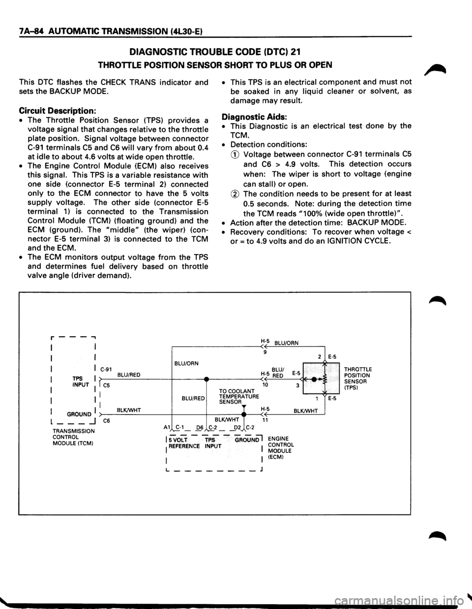
DIAGNOSTIC TROUBLE CODE (DTC) 21
THROTTLE POSITION SENSOR SHORT TO PLUS OR OPEN
This DTC flashes the CHECK TRANS indicator and
sets
the BACKUP MODE.
Circuit Description:
• The Throttle Position Sensor (TPS) provides a
voltage signal that changes relative to the throttle
plate position. Signal voltage between connector
C-91 terminals C5 and C6 will vary from about 0.4
at idle to about 4.6 volts at wide open throttle.
• The Engine Control Module (ECM) also receives
this signal. This TPS is a variable resistance with
one side (connector E-5 terminal 2) connected
only to the ECM connector to have the 5 volts
supply voltage. The other side (connector E-5
terminal 1) is connected to the Transmission
Control Module (TCM) (floating ground) and the
ECM (ground). The "middle" (the wiper) (con
nector E-5 terminal 3) is connected to the TCM
and
the ECM.
• The ECM monitors output voltage from the TPS
and determines fuel delivery based on throttle
valve angle (driver demand).
r---...,
I
I
I
I
I
I
TPS INPUT
I GROUND I L ___ _j
C-91
T C5
I
I
C6
BLU/ORN
BLU/RED
BLU/RED
BLK/WHT
• This TPS is an electrical component and must not
be soaked in any liquid cleaner or solvent, as
damage may result.
Diagnostic Aids:
• This Diagnostic is an electrical test done by the
TCM.
• Detection conditions:
CD Voltage between connector C-91 terminals C5
and C6 > 4.9 volts. This detection occurs
when: The wiper is short to voltage (engine
can
stall) or open.
@ The condition needs to be present for at least
0.5
seconds. Note: during the detection time
the TCM reads "100% (wide open throttle)".
• Action after the detection time: BACKUP MODE.
•
Recovery conditions: To recover when voltage <
or= to 4.9 volts and do an IGNITION CYCLE.
H-5 BLU/ORN
9
BLU/
H-5
RED E-5
-10 3 TO COOLANT TEMPERATURE
1 SENSOR H-5 BLK/WHT
BLK/WHT
11
2 E-5
E-5
THROTTLE POSITION
SENSOR
(TPS)
TRANSMISSION CONTROL MODULE
(TCM)
A1 S.-1_ 06 .,&_2 _ _!>2 C-2
lsvoLT-rps -aRouNDl ENGINE
I REFERENCE INPUT I CONTROL MODULE
I (ECM)
L--------J
Page 958 of 1928
7A-86 AUTOMATIC TRANSMISSION (4L30-E)
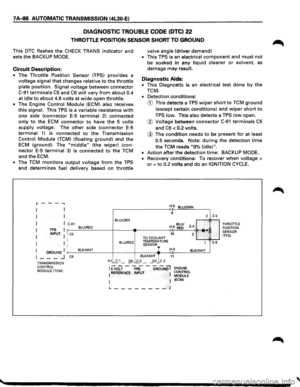
DIAGNOSTIC TROUBLE CODE (DTC) 22
THROTTLE POSITION SENSOR SHORT TO GROUND
This DTC flashes the CHECK TRANS indicator and
sets
the BACKUP MODE.
Circuit Description:
• The Throttle Position Sensor (TPS) provides a
voltage signal that changes relative to the throttle
plate position. Signal voltage between connector
C-91 terminals C5 and C6 will vary from about 0.4
at idle to about 4.6 volts at wide open throttle.
• The Engine Control Module (ECM) also receives
this signal. This TPS is a variable resistance with
one side (connector E-5 terminal 2) connected
only to the ECM connector to have the 5 volts
supply voltage. The other side (connector E-5
terminal 1) is connected to the Transmission
Control Module (TCM) (floating ground) and the
ECM (ground). The "middle" (the wiper) (con
nector E-5 terminal 3) is connected to the TCM
and the ECM.
• The TCM monitors output voltage from the TPS
and determines fuel delivery based on throttle
r---.,
I
I
I
I
I
I
TPS INPUT
I GROUND I L ___ .J
C-91
T C5
I
I
C6
BLU/ORN
BLU/RED
BLU/RED
BLK!WHT
valve angle (driver demand)
• This TPS is an electrical component and must not
be soaked in any liquid cleaner or solvent, as
damage may result.
Diagnostic Aids:
• This Diagnostic is an electrical test done by the
TCM.
• Detection conditions:
G) This detects a TPS wiper short to TCM ground
(except certain conditions) and wiper short to
TPS low. This also detects a TPS low open.
® Voltage between connector C-91 terminals C5
and C6 < 0.2 volts.
@ The condition needs to be present for at least
0.5
seconds. Note: during the detection time
the TCM reads "0% (idle)".
• Action after the detection time: BACKUP MODE.
•
Recovery conditions: To recover when voltage >
or= to 0.2 volts and do an IGNITION CYCLE.
H-5 BLU/ORN
9
BLU/
H- 5 RED E-5 _. 10 3 TO
COOLANT TEMPERATURE
1 SENSOR, H-5 BLK!WHT
BLK!WHT
11
2
:
E-5
E-5
THROTTLE POSITION
SENSOR
(TPS)
TRANSMISSION CONTROL MODULE
(TCM)
A1 S-1_ D6 ._£2-~2_, C-2
lsvo"Lr -"TP5 -"GRouNDl !REFERENCE INPUT 1
I I t_ ________ J
ENGINE
CONTROL MODULE
(ECM)
Page 960 of 1928
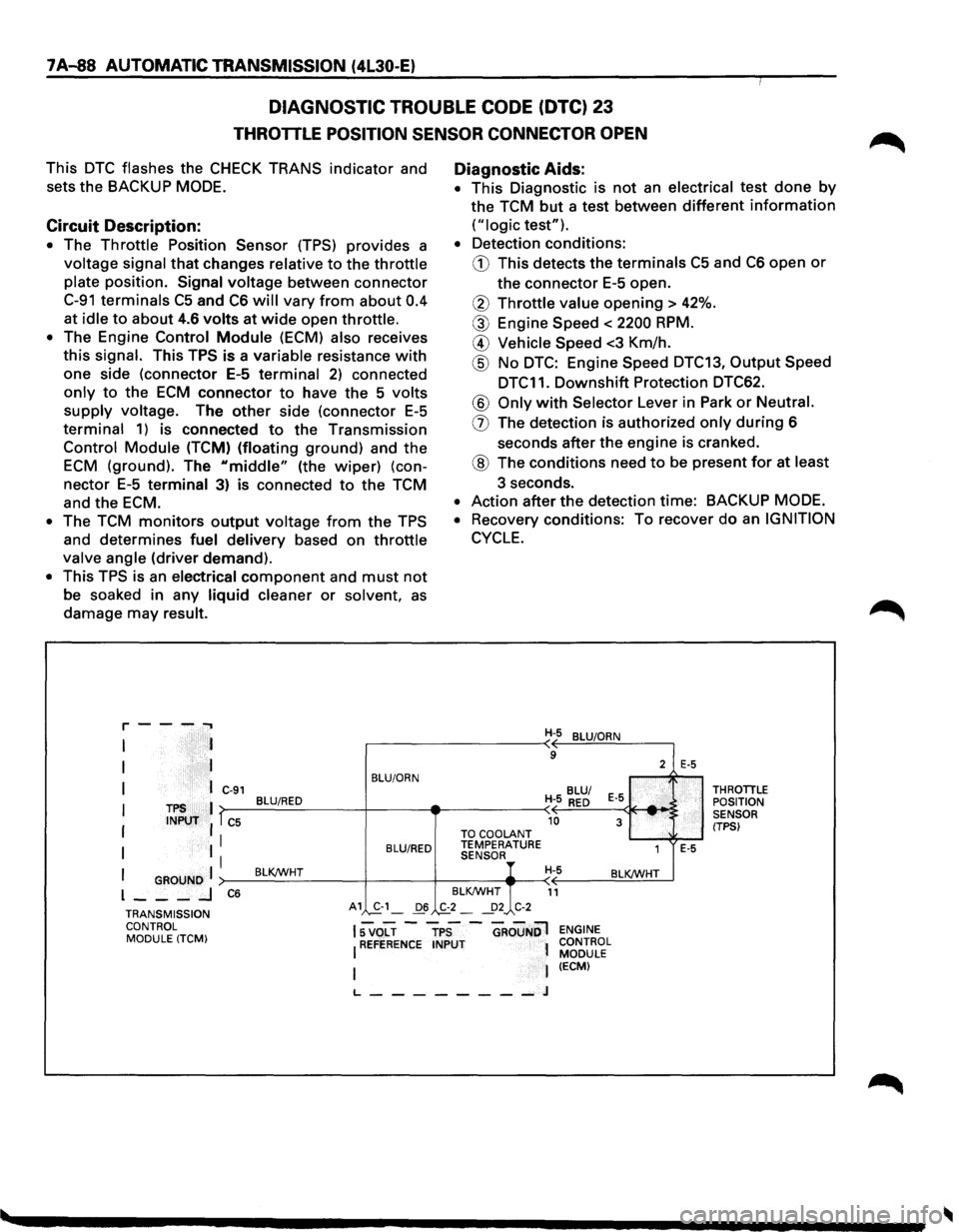
7A-88 AUTOMATIC TRANSMISSION (4l30-E)
DIAGNOSTIC TROUBLE CODE (DTC) 23
THROTTLE POSITION SENSOR CONNECTOR OPEN
This DTC flashes the CHECK TRANS indicator and
sets
the BACKUP MODE.
Circuit Description:
• The Throttle Position Sensor (TPS) provides a
voltage signal that changes relative to the throttle
plate position. Signal voltage between connector
C-91 terminals C5 and C6 will vary from about 0.4
at
idle to about 4.6 volts at wide open throttle.
• The Engine Control Module (ECM) also receives
this signal. This TPS is a variable resistance with
one side (connector E-5 terminal 2) connected
only to the ECM connector to have the 5 volts
supply voltage. The other side (connector E-5
terminal 1) is connected to the Transmission
Control Module (TCM) (floating ground) and the
ECM (ground). The "middle" (the wiper) (con
nector E-5 terminal 3) is connected to the TCM
and
the ECM.
• The TCM monitors output voltage from the TPS
and
determines fuel delivery based on throttle
valve angle (driver demand).
• This TPS is an electrical component and must not
be soaked in any liquid cleaner or solvent, as
damage may result.
r--...... ..,
I
I
I
TPS INPUT
I GROUND I l ___ _J
C-91
l C5
I
I
C6
BLU/ORN
BLU/RED
BLU/RED
BLKJWHT
A1 ,S.-1_ 06
Diagnostic Aids:
• This Diagnostic is not an electrical test done by
the TCM but a test between different information
("logic test").
• Detection conditions:
G) This detects the terminals C5 and C6 open or
the connector E-5 open.
® Throttle value opening > 42%.
® Engine Speed < 2200 RPM.
@ Vehicle Speed <3 Km/h.
@ No DTC: Engine Speed DTC13, Output Speed
DTC11.
Downshift Protection DTC62.
® Only with Selector Lever in Park or Neutral.
(]) The detection is authorized only during 6
seconds
after the engine is cranked.
® The conditions need to be present for at least
3 seconds.
• Action after the detection time: BACKUP MODE.
• Recovery conditions: To recover do an IGNITION
CYCLE.
TO COOLANT TEMPERATURE SENSOR
BLKJWHT
.,£2_ ~2 C-2
H-5 BLUIORN
9
2
BLU/
H- 5
RED E-5
10 3 .... ,'
1
H-5 BLKJWHT
11
E-5
E-5
THROTILE
POSITION
SENSOR
(TPSI
TRANSMISSION CONTROL MODULE (TCM)
15 VOLT -TPS -GROuNOl ENGINE
I REFERENCE INPUT 1 CONTROL l MODULE I (ECM)
L--------J
Page 993 of 1928
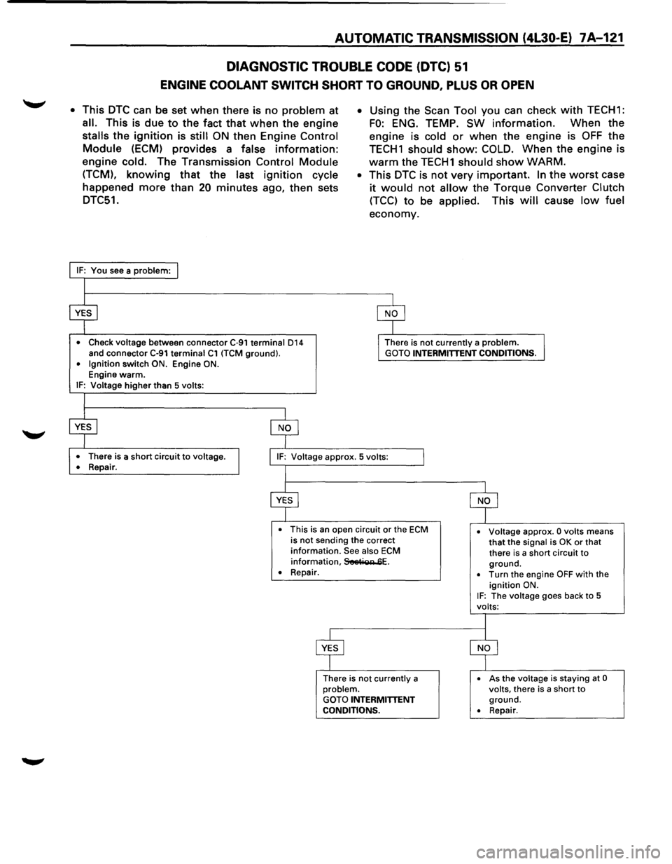
AUTOMATIC TRANSMISSION (4L30-E) 7 A-121
DIAGNOSTIC TROUBLE CODE (DTC) 51
ENGINE COOLANT SWITCH SHORT TO GROUND, PLUS OR OPEN
• This DTC can be set when there is no problem at
all. This is due to the fact that when the engine
stalls the ignition is still ON then Engine Control
Module (ECM) provides a false information:
engine cold. The Transmission Control Module
(TCM), knowing that the last ignition cycle
happened more than 20 minutes ago, then sets
DTC51.
• Check voltage between connector C-91 terminal 014 and connector C-91 terminal C1 (TCM ground). • Ignition switch ON. Engine ON. Engine warm. IF: Voltage higher than 5 volts:
•
There is a short circuit to voltage.
•
Repair.
• Using the Scan Tool you can check with TECH1:
FO: ENG. TEMP. SW information. When the
engine is
cold or when the engine is OFF the
TECH1 should show: COLD. When the engine is
warm the TECH1 should show WARM.
• This DTC is not very important. In the worst case
it would not allow the Torque Converter Clutch
(TCC) to be applied. This will cause low fuel
economy.
There is not currently a problem. GOTO INTERMITTENT CONDITIONS.
• This is an open circuit or the ECM is not sending the correct information. See also ECM information, SeetiQR 6E.
• Voltage approx. 0 volts means that the signal is OK or that
there is a short circuit to ground. • Repair.
There is
not currently a problem. GOTO INTERMITTENT CONDITIONS.
• Turn the engine OFF with the ignition ON. IF: The voltage goes back to 5
volts:
•
As the voltage is staying at 0 volts, there is a short to ground. • Repair.
Page 1159 of 1928
TRANSFER CASE 7D-1
SECTION 70
TRANSFER CASE
w CAUTION:
When fasteners are removed, always reinstall them at the same location from which they were removed. If a
fastener needs
to be replaced, use the correct part number fastener for that application. If the correct part
number is not available, a fastener
of equal size and strength (or stronger) may be used. Fasteners that are
not reused, and those requiring thread locking compound, will
be called out. The correct torque values must
be used when installing fasteners that require torque.
If the above conditions are not followed, parts or
system damage could result.
CONTENTS
General Description ................... 7D-1
Construction . . . . . . . . . . . . . . . . . . . . . . . . . 7D-2
On-Vehicle Service .................... 7D-3
Transfer
Case (A/T) .................. 7D-3
Transfer Rear
Oil Seal ................ 7D-5
Unit Repair ........................... 7D-8
Transfer
Case Assembly (AfT) ........ 7D-8
Transfer Rear
Case Assembly . .
. . . . . 7D-11
Detent, Shift Arm, And
Interlock Pin (Transfer
Case Assembly) . .
. . . . . . . . . . . . . . . . . . 7D-14 Transfer
Case
Assembly . .
. . . . . . . . . .
7D-17
Main Data And Specifications . . . . . . . .
70-29
General
Specifications . .
. . . . . . . . . . . .
70-29
Torque
Specifications ............... 7D-30
Special Tools
........................ 7D-32
GENERAL DESCRIPTION
The transfer case is used to provide a means of
providing power flow to the front axle. The transfer
case also provides a means of disconnecting the front
axle, providing better fuel economy and quieter
operation when the vehicle is driven
on improved
roads where four wheel drive is not required.
In
addition, the transfer case provides an additional gear
reduction when placed in low range, which
is useful
when difficult off-road conditions are encountered. A
floor mounted shift lever is used to select the
operating range. When four wheel drive has been
selected, the four wheel drive indicator light is
designed to come
on when the front axle has been
engaged.
Page 1199 of 1928
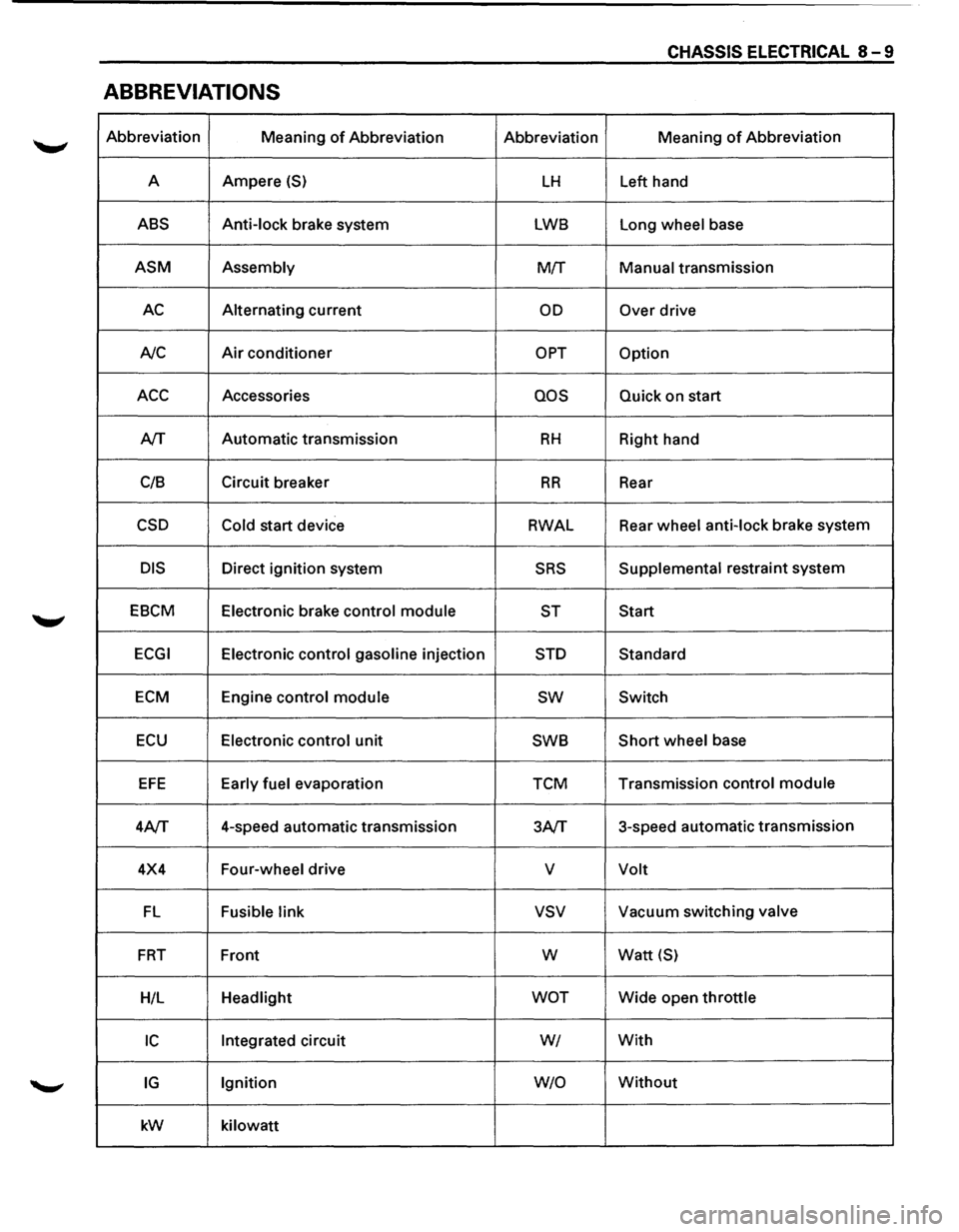
CHASSIS ELECTRICAL 8-9
ABBREVIATIONS
Abbreviation
Meaning of Abbreviation Abbreviation Meaning of Abbreviation
A Ampere
(S) LH Left
hand
ABS Anti-lock brake system LWB Long wheel base
ASM Assembly M!f Manual transmission
AC Alternating current OD Over drive
A/C
Air conditioner OPT Option
ACC Accessories QOS Quick on start
A/T Automatic
transmission
RH Right hand
C/8 Circuit
breaker
RR Rear
CSD Cold start device RWAL Rear
wheel anti-lock brake system
DIS Direct ignition system SRS Supplemental restraint system
EBCM Electronic brake control module
ST Start
ECGI Electronic control gasoline injection STD Standard
ECM Engine control module sw Switch
ECU Electronic control unit SWB Short wheel
base
EFE Early fuel evaporation TCM Transmission
control module
4A/T 4-speed
automatic transmission
3A/T 3-speed
automatic transmission
4X4 Four-wheel drive
v Volt
FL Fusible link vsv Vacuum switching valve
FRT Front w Watt {S)
H/L Headlight WOT Wide open throttle
IC Integrated circuit WI With
IG Ignition W/0 Without
kW
kilowatt
Page 1210 of 1928
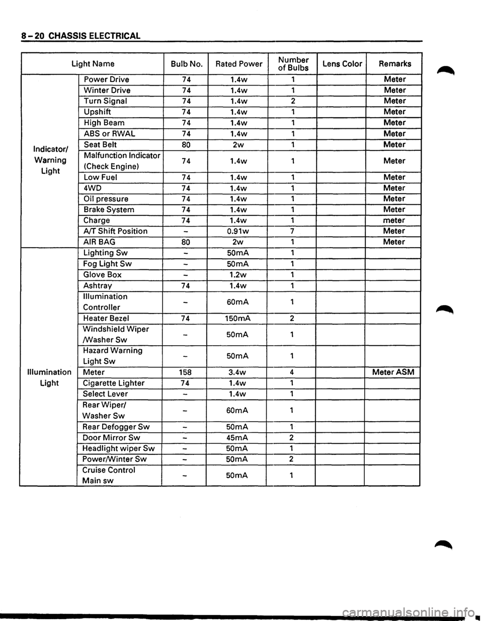
8-20 CHASSIS ELECTRICAL
Light Name Bulb No. Rated Power Number Lens Color Remarks of Bulbs
Power Drive 74 1.4w 1
Meter
Winter Drive 74 1.4w
1 Meter
Turn Signal 74 1.4w 2 Meter
Upshift
74 1.4w 1 Meter
High Beam
74 1.4w 1 Meter
ABSorRWAL 74 1.4w 1 Meter
Indicator/ Seat Belt 80 2w 1 Meter
Warning Malfunction Indicator 74 1.4w
1 Meter
Light (Check
Engine)
Low Fuel 74 1.4w 1 Meter
4WD
74 1.4w 1 Meter
Oil pressure 74 1.4w 1 Meter
Brake System 74 1.4w 1 Meter
Charge 74 1.4w 1
meter
A/T Shift Position -0.91w 7 Meter
AIR BAG 80 2w 1 Meter
Lighting Sw -SOmA 1
Fog Light
Sw -SOmA 1
Glove Box -1.2w 1
Ashtray
74 1.4w 1
Illumination
60mA 1 -Controller
Heater Bezel 74 1SOmA 2
Windshield
Wiper SOmA 1 -/WasherSw
Hazard Warning SOmA 1 -Light Sw
Illumination Meter 158 3.4w 4 MeterASM
Light
Cigarette Lighter
74 1.4w
1
Select Lever -1.4w 1
Rear
Wiper/ 60mA 1 -WasherSw
Rear Defogger Sw -SOmA 1
Door
Mirror Sw -45mA 2
Headlight
wiper Sw -SOmA 1
Power/Winter
Sw -SOmA 2
Cruise Control
SOmA 1 -Main sw
II
Page 1211 of 1928
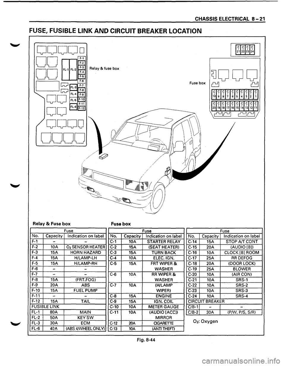
CHASSIS ELECTRICAL 8-21
FUSE, FUSIBLE LINK AND CIRCUIT BREAKER LOCATION
ooooo 112~12~1~1~1
00 E
EEr 00 ~
Relay & fuse box
SJOOO 7-6
I lw ;;::;~ Fuse box ~ ~
1l1~~ ~lff~UIH~Inll
w~ F-a FL-4 ~
00 FL·S~ r---, F-11 'l2~J1~ 1~1&11~11~1,\l~31hl1~1
0
0
FL-6 'F-i2
I' ~
\a~ a~;
0000
0000
I ~
l/
~
j
~/~/ e:;?' v II I / / .I / /
('-/ .
~~
-~-~;,a~ ~~ --.:_
~~~~ -
Relay & Fuse box Fuse box
Fuse
Fuse Fuse
No. Capacity Indication on label No. Capacity Indication on label No. Capacity Indication on label
F-1 --C-1 10A STARTER RELAY
C-14 15A STOP A!f CONT
F-2 10A 02 SENSOR HEATER C-2 15A (SEAT HEATER)
C-15 20A (AUDIO [8))
F-3
15A HORN HAZARD C-3 15A
TURN BACK C-16 10A CLOCK (8] ROOM
F-4
15A H/LAMP-LH C-4 10A ELEC.IGN. C-17 25A RR DEFOG
F-5
15A H/LAMP-RH C-5
15A FRTWIPER & C-18 20A (DOOR LOCK)
F-6 --WASHER C-19
25A BLOWER
F-7
- -C-6 10A RRWIPER & C-20 10A (AIR
CON)
F-8
15A (FRT.FOG) WASHER C-21 10A SRS-1
F-9 20A ABS C-7 10A (H/LAMP C-22 10A SRS-2
F-10
15A FUEL PUMP WIPER) C-23 lOA SRS-3
F-11 -
-C-8 15A ENGINE C-24 10A SRS-4
F-12
15A TAIL C-9 15A IGN. COIL CIRCUIT BREAKER
FUSIBLE
LINK
C-10 10A METER GAUGE
C/8-1 --FL-1 80A MAIN C-11 10A
(AUDIO IACC])
C/8-2 30A (P/W, P/S, S/R)
FL-2 50 A KEYSW MIRROR
FL-3 30A ECM C-12 20A CIGARETTE 02: Oxygen
FL-6 40A (ASS 4/WHEEL ONLY) C-13 10A (ANTI THEFT)
Fig. 8-44