light ISUZU TROOPER 1995 Workshop Manual
[x] Cancel search | Manufacturer: ISUZU, Model Year: 1995, Model line: TROOPER, Model: ISUZU TROOPER 1995Pages: 1928
Page 862 of 1928
6E2-166 DRIVEABILITY AND EMISSIONS
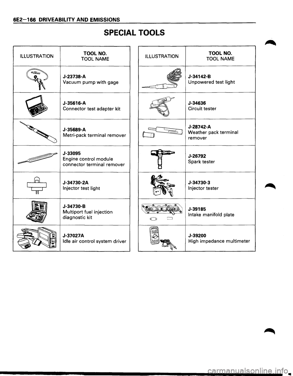
SPECIAL TOOLS
ILLUSTRATION TOOL NO.
TOOL NAME ILLUSTRATION
~
J-23738-A
Vacuum pump with gage
~
J-35616-A
Connector test adapter kit
'
J-35689-A
Metri-pack terminal remover
~
J-33095
Engine control module
connector terminal remover
$
J-34730-2A
Injector test light
•
J-34730-B
Multipart fuel injection
diagnostic kit
~~~ J-37027A
~~~
Idle air control system driver
TOOL NO.
TOOL NAME
J-34142-B
Unpowered test light
J-34636
Circuit tester
J-28742-A
Weather pack terminal
remover
J-26792
Spark tester
J-34730-3
Injector tester
J-39185
Intake manifold plate
J-39200
High impedance multimeter
..
Page 882 of 1928
7A-10 AUTOMATIC TRANSMISSION (4L30-E)
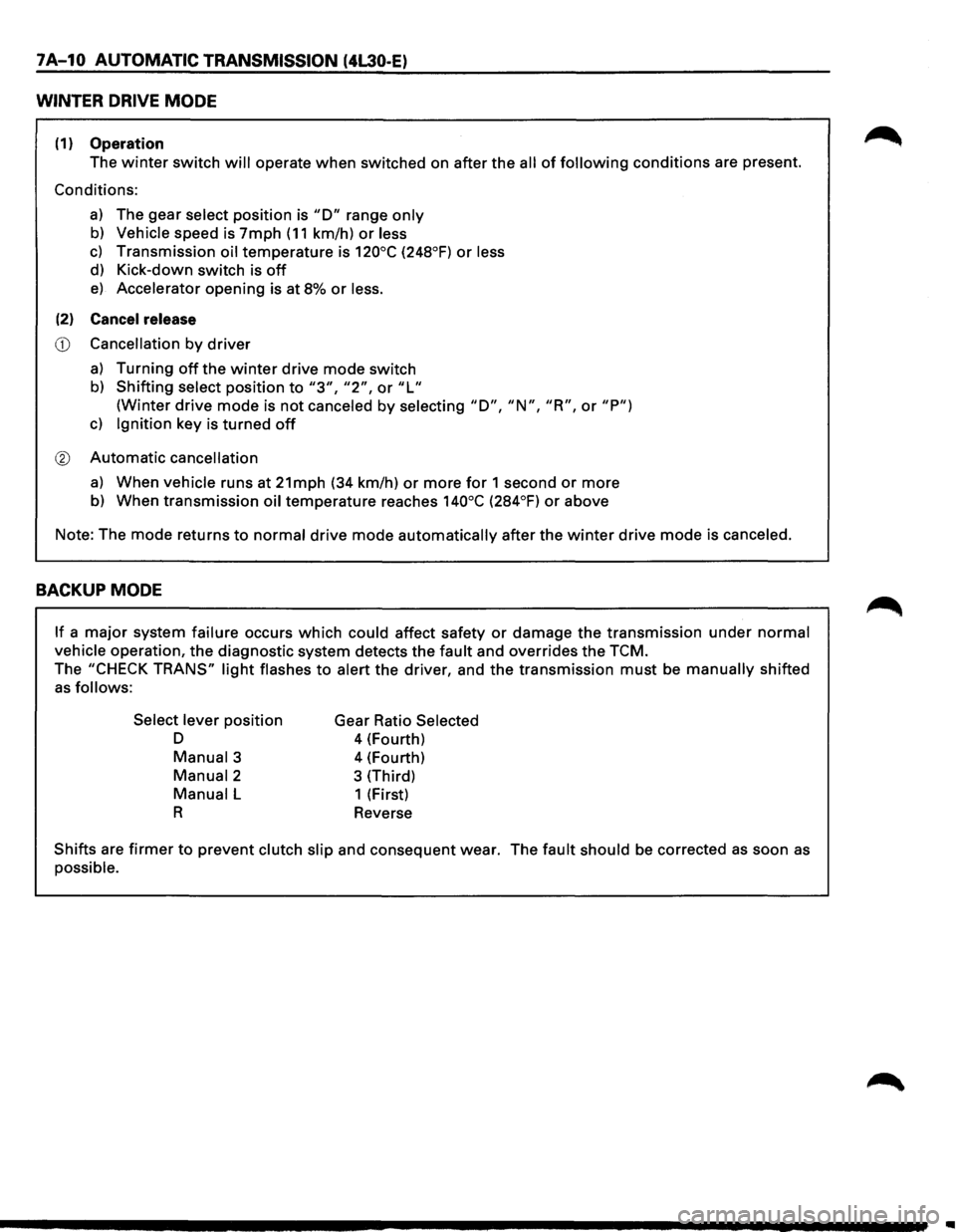
WINTER DRIVE MODE
(1) Operation
The winter switch will operate when switched on after the all of following conditions are present.
Conditions:
a) The gear select position is "D" range only
b) Vehicle speed is 7mph (11 km/h) or less
c) Transmission oil temperature is 120°C (248°F) or less
d) Kick-down switch is off
e) Accelerator opening is at 8% or less.
(2) Cancel release
CD Cancellation by driver
a) Turning off the winter drive mode switch
b) Shifting select position to "3", "2", or "L"
(Winter drive mode is not canceled by selecting "D", "N", "R", or "P")
c) Ignition key is turned off
® Automatic cancellation
a) When vehicle runs at 21mph (34 km/h) or more for 1 second or more
b) When transmission oil temperature reaches 140°C (284°F) or above
Note: The mode returns
to normal drive mode automatically after the winter drive mode is canceled.
BACKUP MODE
If a major system failure occurs which could affect safety or damage the transmission under normal
vehicle operation, the diagnostic system detects the fault and overrides the TCM.
The "CHECK TRANS" light flashes to alert the driver, and the transmission must be manually shifted
as follows:
Select lever
position
D
Manual3
Manual2
Manual L
R
Gear Ratio Selected
4 (Fourth)
4 (Fourth)
3 (Third)
1 (First)
Reverse
Shifts are firmer to prevent clutch slip and consequent wear. The fault should be corrected as soon as
possible.
Page 883 of 1928

AUTOMATIC TRANSMISSION (4L30-E) 7 A-11
FUNCTIONS OF INPUT /OUTPUT COMPONENTS
Components Function
Speed sensor
Senses rotation
of output shaft and feeds the data to Transmission
(fixed
to transmission (T/M)) Control Module (TCM)
Throttle Senses the extent of throttle valve opening and the speed of the throttle
position sensor (TPS) valve lever motion to open the valve and feeds the data to TCM (fed to
(fixed to engine)
Engine Control Module (ECM) also)
I
Brake Switch (SW) Senses whether the driver has pressed the brake pedal or not and feeds
N (fixed
to brake pedal) the
information to TCM
p Kick-down SW (fixed to Senses whether the driver has pushed the accelerator pedal fully or not
u accelerator pedal) and feeds the information to TCM
T Mode
SW (fixed to T/M) Senses the select lever position and feeds the information to TCM
s Power drive SW Senses whether the driver has selected the power mode and feeds the
I (fixed to front console) information to TCM
G T/M
oil temp. sensor
Senses the T/M oil temperature and feeds the data to TCM
N Engine
coolant Senses the engine cooling water temperature and feeds the data to TCM
A temperature
SW (feeds the signal from ECM)
L
Engine speed
signal Feeds the signals monitoring engine speed to TCM from Ignition Control
Module
(fed to ECM also)
Air conditioning Senses whether the air conditioner has been switched on or not and
information feeds the information
to TCM
On-board diagnostic
input By monitoring the Ground (GND), the location of failure is shown on the
T/M
monitor lamp ("CHECK TRANS") by flashing the diagnostic trouble
code
Winter switch
Senses whether the driver has selected the winter mode, and feeds the
(fixed
to front console) information to TCM
Cruise
controller Downshift takes place when Overdrive OFF signal is received from auto
(Overdrive
OFF signal) cruise control unit
Shift
solenoid Selects shift point and gear position suited to the vehicle running con-s 1-2/3-4, 2-3
dition on the basis of TCM output 0 Band apply solenoid
Controls oil flow suited to the vehicle running condition on the basis of L
E TCM output
0 N
Torque
Converter Controls clutch engagement/disengagement suited to the vehicle
u 0 Clutch solenoid running condition on the basis of TCM output
T I Force motor Adjusts the oil pump delivery pressure to line pressure suited to the p D
(Pressure regulator vehicle running condition on the basis of TCM output u valve) T
Power drive mode lamp
Informs the driver whether the vehicle is in power mode or not
s Winter drive mode lamp Informs the driver whether the vehicle is in winter mode or not
I T/M monitor lamp Informs the driver of failure in the system. It also displays the self diagnosis
G
("CHECK TRANS") code.
N Data Link Connector
(DLC) When connected with TECH 1 or tester, can communicate the data for A
L function
check, etc. (fed to ECM also). When TECH 1 is not connected, can
communicate the
signal for torque management with ECM.
Self-diagnosis connector
When short-circuited with the bipolar connector, the T/M monitor lamp
displays
a failure by code.
ATF warning
lamp Lights when ATF oil temperature rises.
ABS signal When the select lever is at "Reverse" or "L" range, sends a signal to the
ABS controller as one of the ABS control conditions.
Page 888 of 1928
7A-16 AUTOMATIC TRANSMISSION (4L30-E)
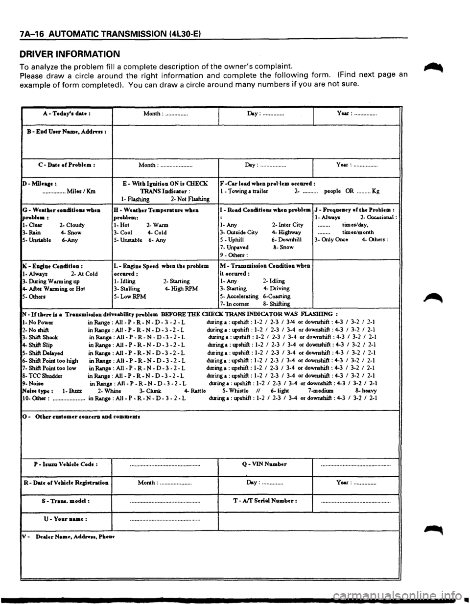
DRIVER INFORMATION
To analyze the problem fill a complete description of the owner's complaint.
Please draw a circle around the right information and complete the following form. (Find next page an
example of form completed). You can draw a circle around many numbers if you are not sure.
A-Today' a date : Month: ............... Day:·············· Year: ...............
B-Ead User Name, Address :
C-Dat~ of Problem : Month: ..................... Day: ................. Year: ................
D-Mileaae: E-With Ignirioa. ON ia OIECK F -Car load wheo proHem oceand :
...............
Miles/Km TRANS lodicator : 1 - Towing a trailer 2-.......... people OR ......... Kg
1-Flashing 2-Not Flashing
G-Weather coa.ditiou whea. H-Weather Temperature whea I -Road Cooditioaa wheu problem J-Frequeucy ofthe Problem :
!Problem: problem: : 1-Always 2-Occuional :
1-Clear 2-Cloudy 1-Hot 2-Warm 1-Any 2-Inter City ........ times/day,
3-
Rain 4-Snow 3-Cool 4-Cold 3-Outsid~ City 4- Highway douooo times/month
5- Unstable
6-Any 5-Unstable 6- Any S-Uphill 6-Downhill 3-
Only Once 4-Otheu:
7-Unpaved 8-Snow
9-Others:
IK-EJI&iae Coaditioa : L-Eagiae Spttd whca the problem M-Traasmissiou Coa.diriou wbea
1-Always 2- At Cold occand: it occund:
3-During Warming up 1-Idling 2-Starting 1-Any 2-
Idling
4-After Warming or Hot 3-Stalling 4-HighRPM 3-Starting 4-Driving
5-Others 5-LowRPM 5-Accelerating 6-Coasting
7-Inc:omer 8-Shifting
N-If then b a Trauamiuioa drivcabillty problem BEFORE TIIE CHECK TRANS
INDICATOR WAS FI..ASHING :
I-No Power in Range: All-P-R-N-D-3 -1-L during
a : upshift : 1-2 I 2-3 I 3~4 or downshift : 4-3 I 3-2 I 2-1
2-No shift in Range :All-P-R-N-D-3-2-L during a: upshift
: 1-2 I 2-3 I 3-4 or downshit : 4-3 I 3-2 I 2-1
3- Shift Shock in Range: All-P-R-N-D -3-2-L during a
:upshift : 1-2 I 2-3 I 3-4 or downshift : 4-3 I 3-2 I 2-1
4-Shift Slip in Range: Ali-P-R-N -D-3 -2 -L during a: upshift : 1-2 I 2-3 I 3-4 or downshift : 4-3 I 3-2 I 2-1
5-Shift Delayed in Range : All -P -R-N - D - 3 - 2 - L during a: upshift :
1-2 I 2-3 I 3-4 or downshift : 4-3 I 3-2 I 2-1
6-Shi1 Point too high in Range :All -P-R-N-D-3-2. L during a: upshift:
1-2 I 2-3 I 3-4 or downshift: 4-3 I 3-2 I 2-1
7-Shift Point too low
in Range : All -P -R-N-D-3 -2-L during
a : upshift : 1-2 I 2-3 I 3-4 or downshift : 4-3 I 3-2 I 2-1
S-TCC Shudder in Range :All-P-R. N-D-3-2-L during a: upshift
: 1-2 I 2-3 I 3-4 or downshift : 4-3 I 3-2 I 2-1
9-Noise in Range : All -P -R-N - D - 3 - 2 - L during a: upshift : 1-2 I 2-3 I 3-4 or downshift : 4-3 I 3-2 I 2-1
INolae type: 1-Buzz 2-Whine 3-Clunk 4-Rattle S-Whistle II 6-light 7-medium 8-hoavy
10-Other: ..................... in Range : All -P -R-N - D - 3 - 2 - L during a: upshit :
1-2 I 2-3 I 3-4 or downshift : 4-3 I 3-2 I 2-1
0-Other cDitomer co aura. aad commeats
P •
bUZD Vebiele Code : ooo,0ooooooooooou• .. ouooooooooooooo•••••o•U Q-VIN Number ··················\
··················\
··········
R-Date orVebiclc Regjatratiou Month: ..................... Day: .............. Year: ...............
S • Traua. model: .................... -. ......................... T-Aff Serial Number : uo••••••••••••••••••\
•••oo•oooooooooooooouooo
U-Your aame: ··················\
··················\
··········
y. Dealer Naau, Addn .. , Pbou~
•
Page 889 of 1928
AUTOMATIC TRANSMISSION (4L30-E) 7A-17
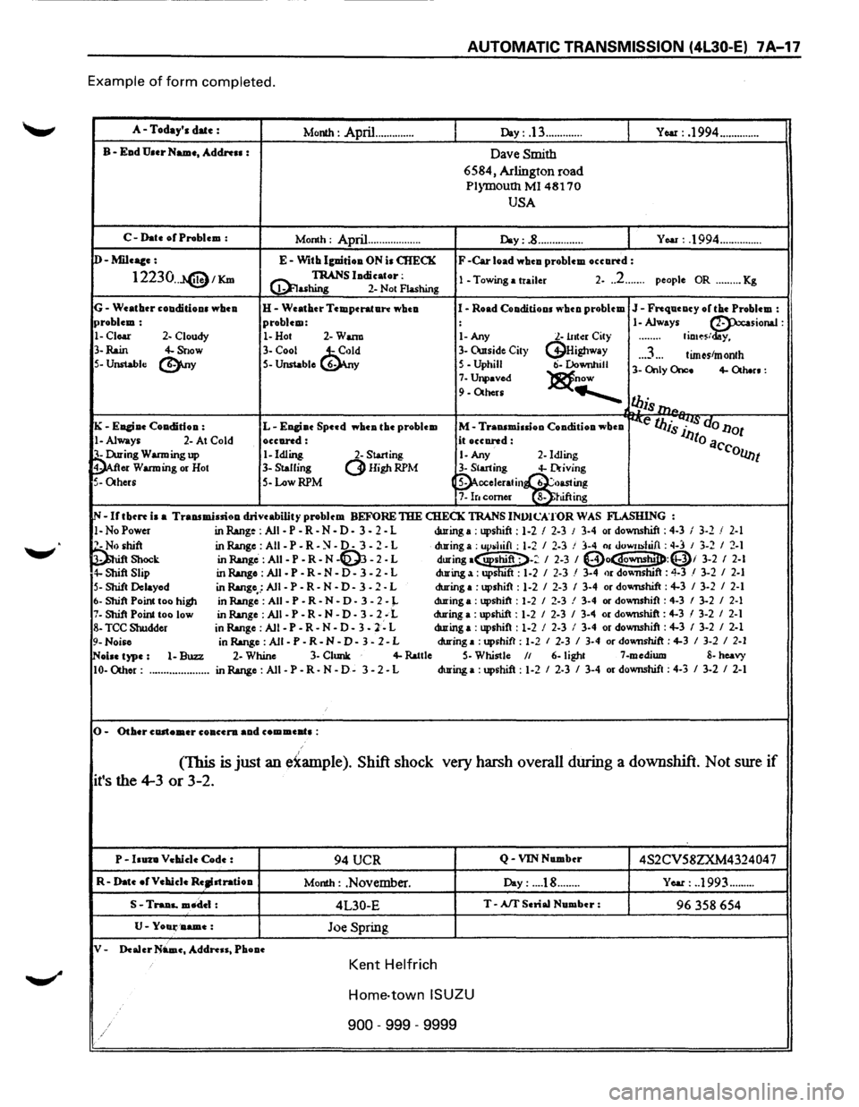
Example of form completed.
A-Today's date : Month : April .............. Day: .13 ............. YOM: .1994 ..............
B-Ead U.er Name, Address : Dave Smith
6584, Arlington road
P1ymoutll Ml 48170
USA
C-Date or Problem :
Month : April... ................ Day:.8 ................ You : .1994 ...............
D-Mileace: E-With lguirioa ON is CHECK F -Car load whcu problem occartd:
12230 .. J.@1Km @! TRANS ludicator: 1 -Towing a trailer 2-.. 2 ....... people OR ......... Kg ashing 2-
Not Flashing
G-Weatbtr couditious wbeu H-Weather Temperature wheu I-Road Conditions ""hen problem J-Frequency or the Problem : problem: problem: : 1-Always ~sionaJ :
1-Clear 2- Cloudy 1-Hot 2-Wann 1-Any l.-lltto:r City ........ fio•~s/ y,
3-
Rain 4-Snow 3-Cool ~d 3-Owside City (j}Highway .. .3 ... tim~stmonth 5-Unstable (!).ny S-Unstable 6- y 5-Uphill ti-Downhill 3-Only Once 4-Otb.n: 7-Unpaved )8t.now 9-Others .......___
l!Jis 111P.
K -Euciue Coa.dition : L-Engiue Speed wbea the problem M-Traasmiuioo Condition wheu ~e IJJis 7~~· do l1ot
!-Always 2-At Cold occared: it occared: lJto a
~ing Warming up 1-Idling 2-Starting 1-Any 2-Idling C'collnt
er Warming
or Hot 3-Stalling (3Higt~RPM 3-Starting 4-Driving
5-Others S-Low RPM (~cceleratin~~~~g 7-lr. comer 8-JUftmg
IN-Irtbcrt is a Transmission drive ability problem BEFORE THE CHECK TRANS INVJCATOR WAS FLASHING :
1-NoPower in Range : All -P -R-N-D-3 - 2 - L during a: upshift: 1-2 I 2-3 J 3-4 or downshift: 4-3 I 3-2 / 2-1
~hift inR.ange:AII-P-R-~-0-3-2-L during a : up~hifl : 1-2 I 2-3 ! 3-4 01 uowushifl : ~-3 I 3-2 I 2-1 Shock in Range: AII-P-R-N -~ -2-L during·~-: I 2-3 I (Do~:Qi 3-2 I 2-l 4-Shift Slip in Range : All -P -R-N - D - 3 - 2 - L during a: ups "ft : 1-2 I 2-3 / 3-4 or dov.nshift : 4-3 / 3-2 I 2-1
S-Shift Delayed
in Range,.: All -P -R-N -D-3 -2 - L during
a :upshift : 1-2 I 2-3 I 3-4 or dovmshift : 4-3 I 3-2 I 2-1
6-Shift Point too higJl in Range :All -P-R-N • D-3-2-J.. during a : upshift : 1-2 I 2-3 ! 3-4 or downshift : 4-3 I 3-2 I 2-1 7-Shift Point too low
in Range :All -P-R-N-D-3-2; L during a :upshift : 1-2 I 2-3 I 3-4 or downshift : 4-3 I 3-2 I 2-1
8-TCC Shudder
in Range : All -P - R
- N - D - 3 -2 - L during
a :upshift : 1-2 I 2-3 I 3-4 or downshift : 4-3 I 3-2 I 2-1
9-Noise in Range : All -P -R-N -D-3 -2-L during a :upshift : 1-2 I 2-3 I 3-4 or downshift : 4-3 I 3-2 I 2-1
~oise type: 1-Buzz 2-Whine 3-Clunk 4-lWtle S-Whistle II 6-light 7-medium 8-heavy
10-0thor: ..................... inR.ange:AII-P-R-N-0-3-2-L during
a :upshift : 1-2 I 2-3 I 3-4 or downshift : 4-3 I 3-2 I 2-1
0-Other customer co accra aa.d com meat• :
(This is just an e~ample ). Shift shock very harsh
overall during a downshift. Not sure if
it's the 4-3 or 3-2.
P-huza Vehicle Code : 94 UCR Q -VIN Number 4S2CV58ZXM432404 7
R-Date ofVehieJe Re~stratioa Month : .November. Day: ... .18 ........ Year: . .1993 .........
S -Traaa.. mtldel : 4L30-E T-Aff Serial Number : 96 358 654
U-Yoali'D.ame: Joe Spring
V-Dealer Name, Address, Phooe
Kent Helfrich
Home-town ISUZU
900 -999 -9999
Page 892 of 1928
7 A-20 AUTOMATIC TRANSMISSION (4L30-E)
CHECKING TRANSMISSION FLUID
LEVEL AND CONDITION
Checking fluid level and condition (color and odor)
at
regular intervals will provide early diagnosis
information about the transmission. This inform
ation may be used to correct a condition that, if not
detected early, could result in major transmission
repairs.
IMPORTANT: When new, automatic transmission
fluid is red in color. As the vehicle is driven, the
transmission
fluid will begin to look darker in color.
The
color may eventually appear light brown.
A DARK
brown color with burnt odor may indicate
excessive
fluid deterioration and signal a need for
fluid change.
FLUID LEVEL
When adding
or changing fluid, use only DEXRON
®-Ill.
Refer to the Maintenance and Lubrication (Section 0
of this manual) for maintenance information and
servicing
interval.
\f CAUTION: DO NOT OVERFILL
Overfilling will cause foaming, loss ~f fluid,
abnormal shifting and possible damage to
the transmission.
1. Start engine and drive vehicle until normal AfT
oil operating temperature is reached:
NOTE: The automatic transmission fluid level
must be checked with the vehicle at normal
A/T oil operating temperature: 75 TO 85°C
(167 TO 185°F) MEASURED WITH TECH1 SCAN
TOOL.
Temperature will greatly affect transmission
fluid level.
If the vehicle is not at normal AfT oil operating
temperature and the proper checking
procedures are
not followed, the result could
be a false reading of the fluid level indicator
and
an incorrect adjustment of the fluid level.
2. Park vehicle on level ground.
3. Move gear selector to "Park".
4. Apply parking brake and block wheels.
5. Allow vehicle to idle for 3 minutes with all
accessories turned off.
6. Check fluid level with engine running at idle:
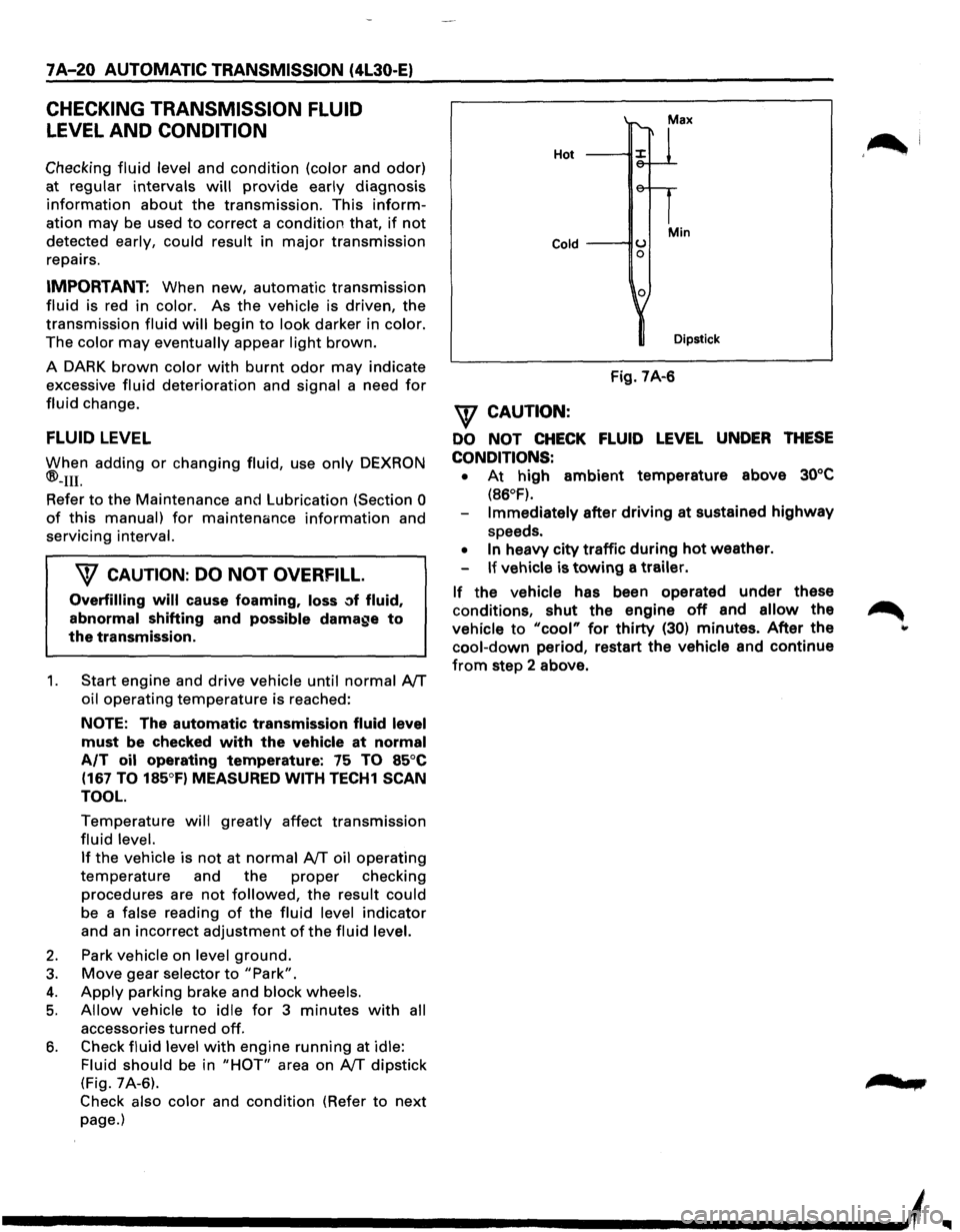
Fluid should
be in "HOT" area on AfT dipstick
(Fig. 7A-6).
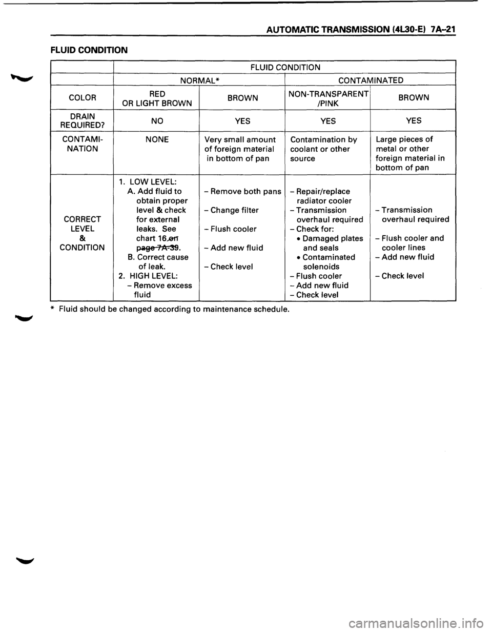
Check also color and condition (Refer to next
page.)
Hot
Cold ---IIU 0
0
Min
Dipstick
Fig. 7A-6
\f CAUTION:
DO NOT CHECK FLUID LEVEL UNDER THESE
CONDITIONS: •
At high ambient temperature above 30°C
(86°F).
Immediately after driving at sustained highway
speeds.
• In heavy city traffic during hot weather.
If vehicle is towing a trailer.
If the vehicle has been operated under these
conditions,
shut the engine off and allow the
vehicle to "cool" for thirty (30) minutes. After the
cool-down period, restart the vehicle and continue
from step 2 above.
'~I
......
Page 893 of 1928
AUTOMATIC TRANSMISSION (4L30-E) 7A-21
FLUID CONDITION
FLUID CONDITION
NORMAL* CONTAMINATED
COLOR
RED BROWN NON-TRANSPARENT BROWN OR LIGHT BROWN
/PINK
DRAIN NO
YES YES YES
REQUIRED?
CO NT AMI- NONE Very small amount Contamination by Large pieces of
NATION of foreign material coolant or other metal or other
in bottom of pan
source foreign material in
bottom of pan
1. LOW LEVEL:
A. Add fluid to -
Remove both pans -Repair/replace
obtain
proper radiator cooler
level
& check -Change filter -Transmission -Transmission
CORRECT for external overhaul required overhaul required
LEVEL leaks. See -Flush cooler -Check for:
& chart 16..811 • Damaged plates -Flush cooler and
CONDITION ~· -Add new fluid and seals cooler
lines
B. Correct cause • Contaminated -Add new fluid
of leak. -Check level solenoids
2. HIGH LEVEL: -Flush cooler -Check level
-Remove excess -Add new fluid
fluid -Check level
* Fluid should be changed according to maintenance schedule.
Page 924 of 1928
7A..J52 AUTOMATIC TRANSMISSION (4l30-E)
TECH1 CONNECTION
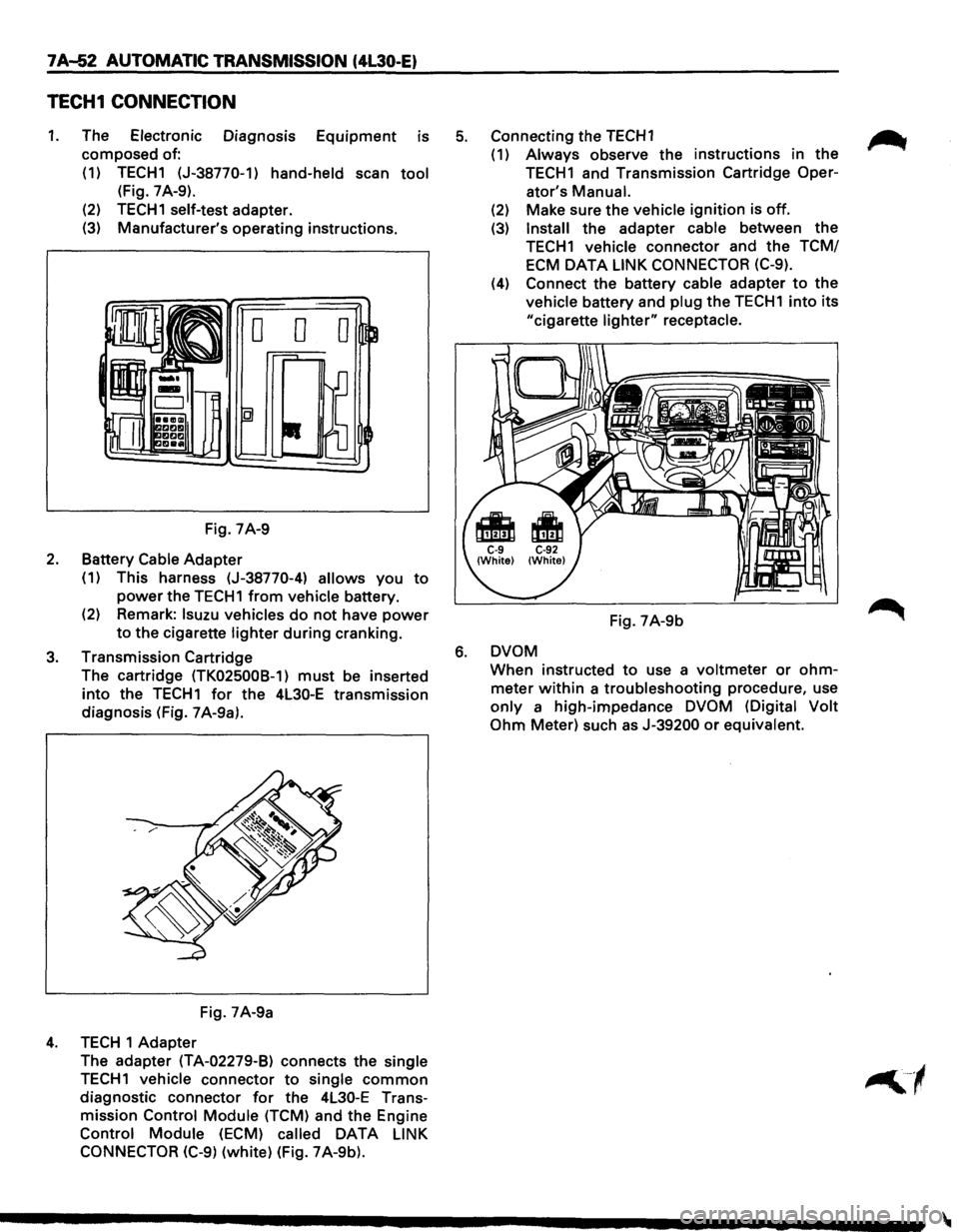
1. The Electronic Diagnosis Equipment is
composed of:
(1) TECH1 (J-38770-1)
hand-held scan tool
(Fig. 7 A-9).
(2)
TECH1 self-test adapter.
(3) Manufacturer's operating instructions.
Fig. 7A-9
2. Battery Cable Adapter
(1) This harness (J-38770-4) allows you to
power the TECH1 from vehicle battery.
(2) Remark:
lsuzu vehicles do not have power
to the cigarette lighter during cranking.
3. Transmission Cartridge
The cartridge
(TK025008-1) must be inserted
into the TECH1 for the 4L30-E transmission
diagnosis (Fig. 7 A-9a).
Fig. 7A-9a
4. TECH 1 Adapter
The adapter
(TA-02279-B) connects the single
TECH1 vehicle connector to single common
diagnostic connector for the 4L30-E Trans
mission
Control Module (TCM) and the Engine
Control Module (ECM) called DATA LINK
CONNECTOR (C-9)
(white) (Fig. 7A-9b).
5. Connecting the TECH1 ~
(1) Always observe the instructions in the
TECH1 and Transmission Cartridge Oper-
ator's
Manual.
(2) Make sure the vehicle ignition is off.
(3) Install the adapter cable between the
TECH1 vehicle connector and the TCM/
ECM
DATA LINK CONNECTOR (C-9).
(4) Connect the battery cable adapter to the
vehicle battery and plug the TECH1 into its
"cigarette lighter" receptacle.
Fig. 7A-9b
6. DVOM
When instructed to use a voltmeter or ohm
meter within a troubleshooting procedure, use
only a high-impedance DVOM (Digital Volt
Ohm
Meter) such as J-39200 or equivalent.
Page 1000 of 1928
7A-128 AUTOMATIC TRANSMISSION (4L30-E)
DIAGNOSTIC TROUBLE CODE (DTC) 55
BRAKE SWITCH SHORT TO GROUND OR OPEN
This DTC does NOT flash the CHECK TRANS
indicator and does NOT set the BACKUP MODE.
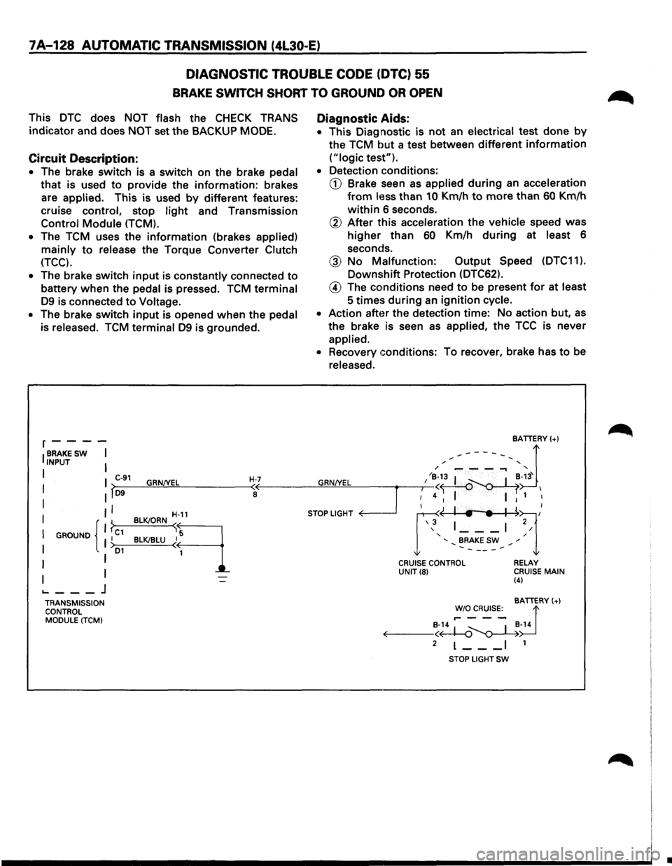
Circuit Description:
• The brake switch is a switch on the brake pedal
that is used to provide the information: brakes
are
applied. This is used by different features:
cruise control, stop
light and Transmission
Control Module (TCM).
•
The TCM uses the information (brakes applied)
mainly to release the Torque Converter Clutch
(TCC).
•
The brake switch input is constantly connected to
battery when the pedal is pressed. TCM terminal
D9 is connected to Voltage.
• The brake switch input is opened when the pedal
is released.
TCM terminal D9 is grounded.
r----
IBRAKESW I INPUT I
I I C-91 GRN/YEL H-7 I >-D9--~~~------~<
I II a
II
I GROUND I C1 I { }
I I >D1
I I
I I ._ ___ j
TRANSMISSION
CONTROL
MODULE (TCM) BLK!ORN
~-11
B~LU~q
Diagnostic
Aids:
• This Diagnostic is not an electrical test done by
the TCM but a test between different information
("logic test").
• Detection conditions:
CD Brake seen as applied during an acceleration
from less than 10 Km/h to more than 60 Km/h
within 6 seconds.
@ After this acceleration the vehicle speed was
higher than 60 Km/h during at least 6
seconds.
@ No Malfunction: Output Speed (DTC11 ).
Downshift Protection (DTC62).
@ The conditions need to be present for at least
5
times during an ignition cycle.
• Action after the detection time: No action but, as
the brake is seen as applied, the TCC is never
applied.
• Recovery conditions: To recover, brake has to be
released.
CRUISE CONTROL UNIT(8) RELAY
CRUISE MAIN (4)
BATTERY(+)
!'~~s:_ d B-14 ~ _ I _B-14 ~--<~~
2 L--_I 1
STOP LIGHT SW
•
Page 1002 of 1928
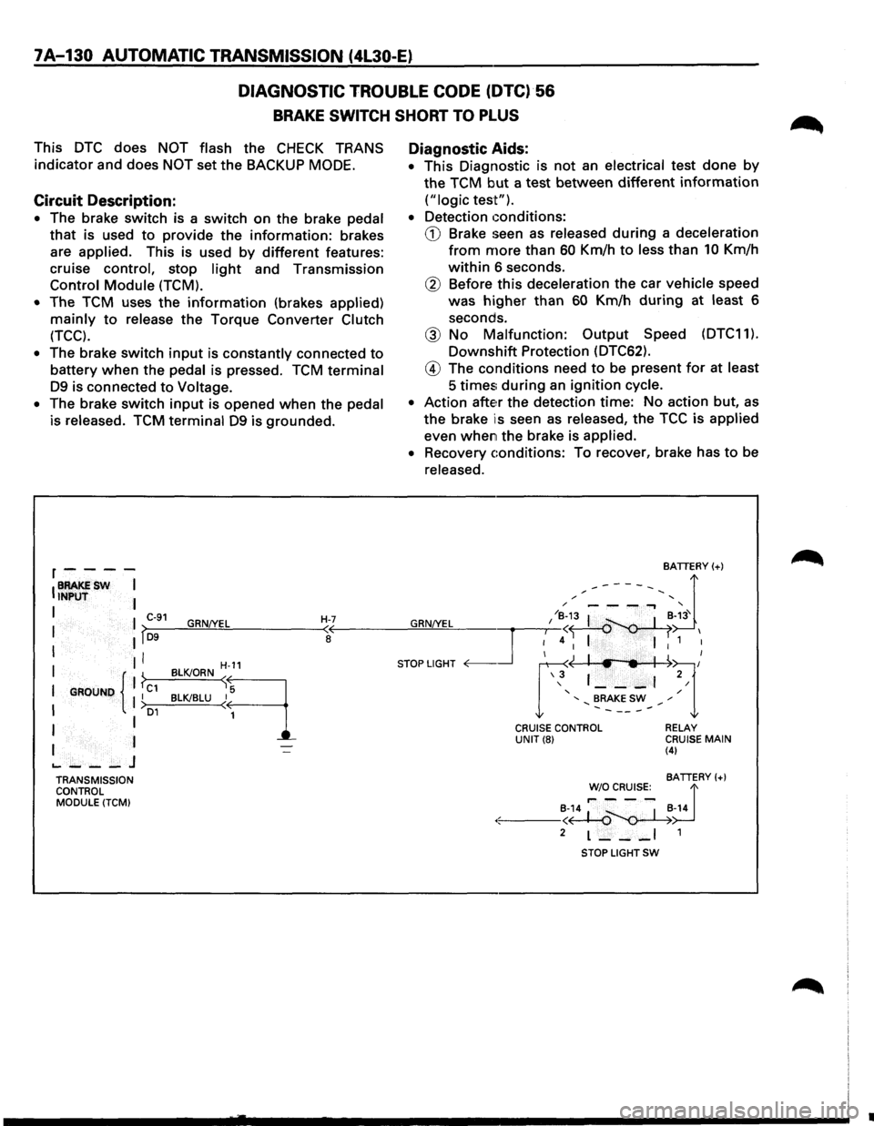
7A-130 AUTOMATIC TRANSMISSION (4l30-E)
DIAGNOSTIC
TROUBLE CODE (DTC)·56
BRAKE SWITCH SHORT TO PLUS
This DTC does NOT flash the CHECK TRANS
indicator and does
NOT set the BACKUP MODE.
Circuit Description:
• The brake switch is a switch on the brake pedal
that is used to provide the information: brakes
are
applied. This is used by different features:
cruise
control, stop light and Transmission
Control Module (TCM).
•
The TCM uses the information (brakes applied)
mainly to release the Torque Converter Clutch
(TCC).
• The brake switch input is constantly connected to
battery when the pedal is pressed. TCM terminal
D9 is connected to Voltage.
•
The brake switch input is opened when the pedal
is released. TCM terminal D9 is grounded.
r----
IBRAKESW I INPUT I
I I C-91 GRN!YEL H-7 I lf~D-9--~~~------~~
I II I
I GROUND { 1 ?c1 II I >o1
I I
I I
.._ ___ J
TRANSMISSION
CONTROL
MODULE (TCM)
H-11
BLK!ORN sq
BLK!BLU ~
1
Diagnostic Aids:
• This Diagnostic is not an electrical test done by
the TCM but a test between different information
("logic test").
•
Detection conditions:
CD Brake seen as released during a deceleration
from more than 60 Km/h to less than 10 Km/h
within 6 seconds.
® Before this deceleration the car vehicle speed
was
higher than 60 Km/h during at least 6
seconds.
@ No Malfunction: Output Speed (DTC11).
Downshift Protection (DTC62).
@ The conditions need to be present for at least
5 times; during an ignition cycle.
•
Action atte~r the detection time: No action but, as
the brake is seen as released, the TCC is applied
even when the brake is applied.
•
Recovery conditions: To recover, brake has to be
released.
BATTERY(+)
,.------, d / '
GRN/YEL I /~;3 I ~-~3' I
~4 I I 1 I
STOP LIGHT <0---.Jr ~~l/ \3 1 ___ , 2/
' / ' BRAKE SW ,. .......... -----.......
CRUISE CONTROL UNIT(8) RELAY CRUISE MAIN (4)
BATTERY(+)
~~~R~s:_ d
·:.:-: ---~~~-14
2 L--_I 1
STOP LIGHT SW
•