light ISUZU TROOPER 1995 Workshop Manual
[x] Cancel search | Manufacturer: ISUZU, Model Year: 1995, Model line: TROOPER, Model: ISUZU TROOPER 1995Pages: 1928
Page 1016 of 1928
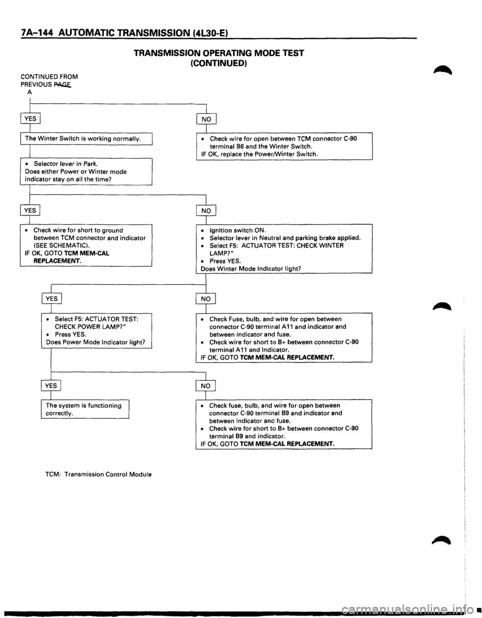
7A-144 AUTOMATIC TRANSMISSION (4L30-E)
TRANSMISSION OPERATING MODE TEST
(CONTINUED)
CONTINUED FROM
PREVIOUS
PAGE. A
I
$
The Winter Switch is working normally.
I
• Selector lever in Park .
Does
either Power or Winter mode indicator stay on all the time?
I
$
• Check wire for short to ground
between
TCM connector and indicator (SEE SCHEMATIC).
IF OK, GOTO TCM MEM-CAL REPLACEMENT.
$
• Select F5: ACTUATOR TEST: CHECK POWER LAMP?"
• Press YES .
Does Power Mode Indicator light?
~
The system is functioning
J correctly.
TCM:
Transmission Control Module
$
• Check wire for open between TCM connector C-90 terminal 86 and the Winter Switch.
IF OK, replace the Power/Winter Switch.
$
• Ignition switch ON .
• Selector lever in Neutral and parking brake applied .
• Select F5: ACTUATOR TEST: CHECK WINTER
LAMP?"
• Press YES .
Does Winter Mode Indicator light?
I
$
• Check Fuse, bulb, and wire for open between
connector C-90 terminal A 11 and indicator and
between indicator and fuse.
• Check wire for short til 8+ between connector C-90
terminal A 11 and Indicator. IF OK, GOTO TCM MEM-CAL REPLACEMENT.
$
• Check fuse, bulb, and wire for open between
connector C-90 terminal 89 and indicator and
between indicator andl fuse.
• Check wire for short to 8+ between connector C-90 terminal 89 and indicator.
IF OK, GOTO TCM MEM-CAL REPLACEMENT.
•
Page 1018 of 1928
7A-146 AUTOMATIC TRANSMISSION (4L30-E)
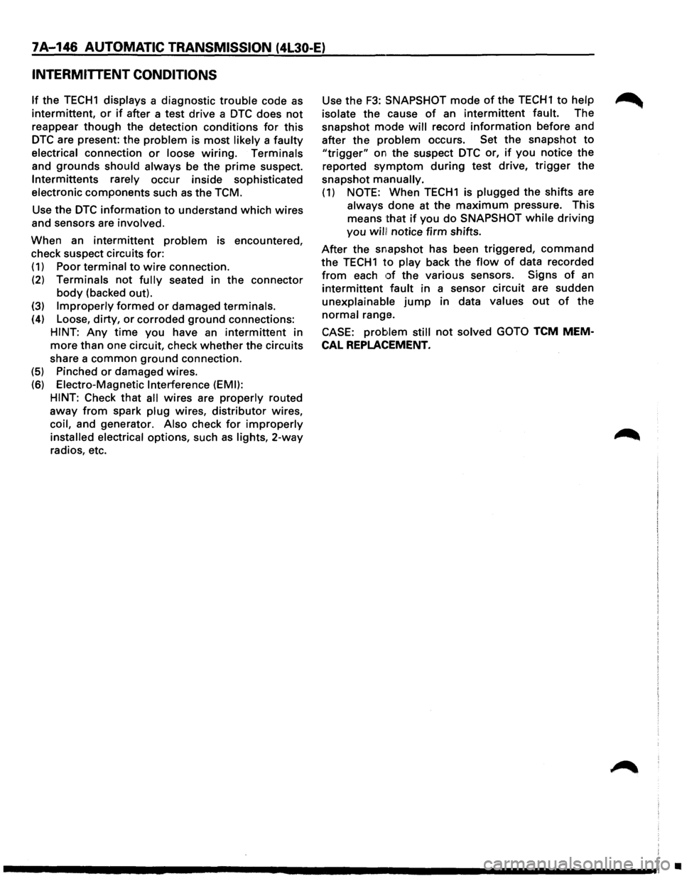
INTERMITTENT CONDITIONS
If the TECH1 displays a diagnostic trouble code as
intermittent, or if after a test drive a DTC does not
reappear though the detection conditions for this
DTC are present: the problem is most likely a faulty
electrical connection or loose wiring. Terminals
and
grounds should always be the prime suspect.
lntermittents rarely occur inside sophisticated
electronic components such
as the TCM.
Use the
DTC information to understand which wires
and sensors are involved.
When an
intermittent problem is encountered,
check suspect circuits for:
(1) Poor terminal to wire connection.
(2) Terminals not fully seated in the connector
body (backed out).
(3) Improperly formed or damaged terminals.
(4) Loose, dirty, or corroded ground connections:
HINT: Any time you have an intermittent in
more than one circuit, check whether the circuits
share a
common ground connection.
(5) Pinched or damaged wires.
(6) Electro-Magnetic Interference (EMI):
HINT:
Check that all wires are properly routed
away from spark plug wires, distributor wires,
coil, and generator. Also check
for improperly
installed electrical options, such as lights, 2-way
radios, etc. Use
the
F3: SNAPSHOT mode of the TECH 1 to help
isolate the cause
of an intermittent fault. The
snapshot
mode will record information before and
after the problem occurs. Set the snapshot
to
"trigger" on the suspect DTC or, if you notice the
reported
symptom during test drive, trigger the
snapshot
manually.
(1) NOTE: When TECH1 is plugged the shifts are
always
done at the maximum pressure. This
means
that if you do SNAPSHOT while driving
you will! notice firm shifts.
After the snapshot has been triggered, command
the TECH1 to play back the flow of data recorded
from each of the various sensors. Signs of an
intermittent fault in a sensor circuit are sudden
unexplainable jump in data values out of the
normal range.
CASE:
problem still not solved GOTO TCM MEM
CAL REPLACEMENT.
•
Page 1022 of 1928
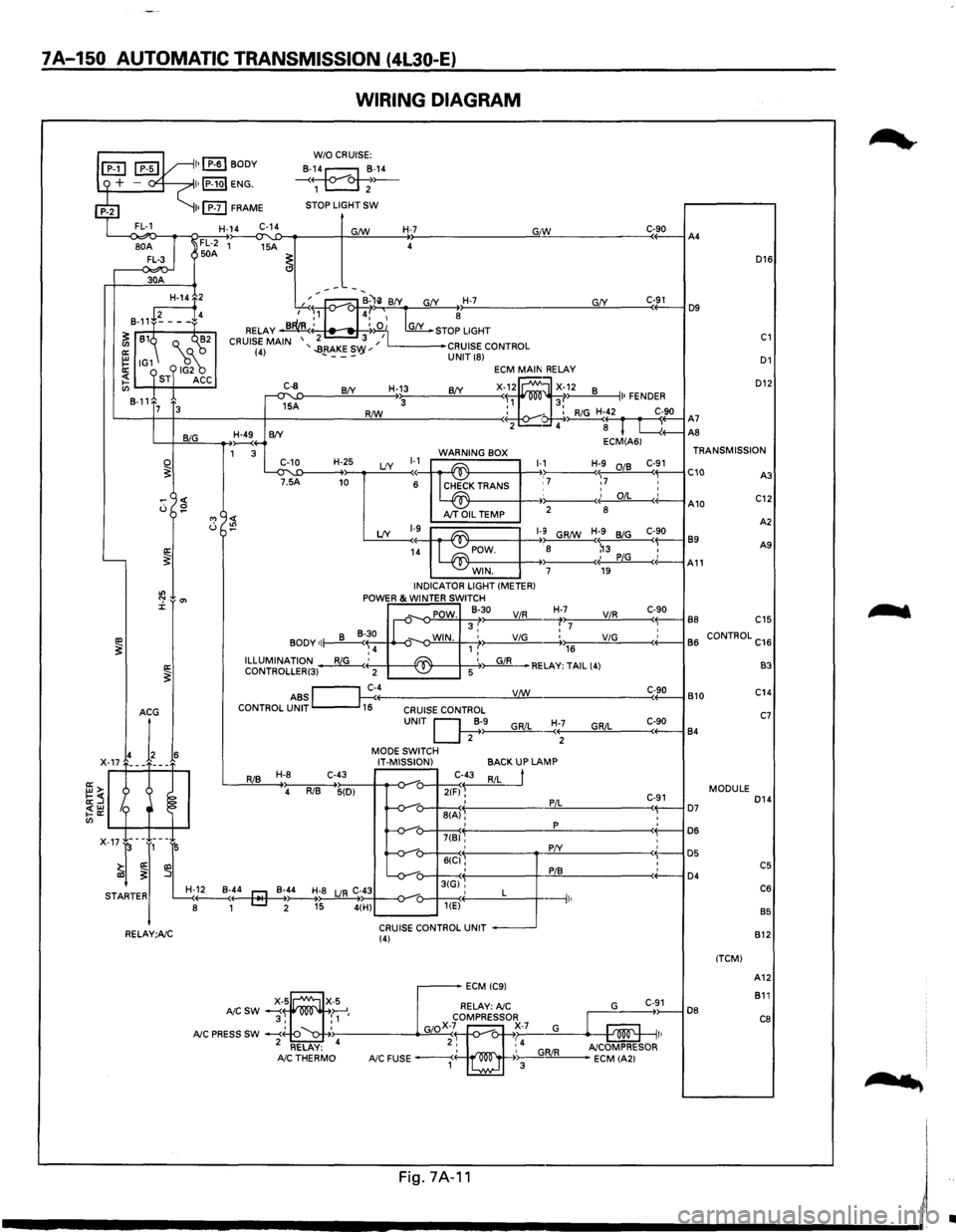
7A-150 AUTOMATIC TRANSMISSION (4L30-E)
WIRING DIAGRAM
L--<~o-~~~~~~--~~~----~~~----~~--------------~G"IW~------------C«-9_0--iA4
D16
30A
D12
GfY ---~:at--B-'li BfY G(Y H-7 ,...-..~., 4,' ~ ~
RELAY ~' ~:iO 1 [my_ STOP LIGHT
2 3 I CRUISE MAIN '..BRAKES '' L------•CRUISE CONTROL (4) - ---vy UNIT (8) D1
~2
8-11+~---f4
~ 81~ Q._ ("'~2
~ IG1 18~ ~ ST ACC en 8-11
C-91 D9
C1
ECM MAIN RELAY
X-f~ ~X~~2 8 II• FENDER R/W : - : RiG H-42 C-90 '-----t--t------+-------!:!Lll----------< • ~( r fl A7 2 4 8 L....{+--AS
C-8
~A
H-13 BfY BfY 3 7 3
L-+-JB~~I,_IG __ __....,~4-B(Y ECM(A61 1 3 WARNING BOX TRANSMISSION
~T'~5'-'1:D----H-+~2~5 LfY ~~~ ~K TRANS 1-,17 Hr7 :~ C-~1 C10 C::
0 ~
"' <( u :!?
'----~
"' ":' 0'> J:
IXl ~ a: ~
I~ A10 AJT OIL TEMP 2
8
A
2
LfY 1-9~ ~1-9 GR/W H;9 BiG C-90 89 1~ POW. : 8 ~3 , A9
- -~· PiG c(-A11 WIN. 7 19 INDICATOR LIGHT (METER) POWER & WINTER SWITCH
_,. POW. 8-30 ViR H-,>,7:;-----'V"-'iR.!..,_ ___ c<-~9-0-l B8 C15 II-v 3, :7 • BODY of~~ ~-o-WIN. 1 ,' ViG -----.+.,.,176 __ ____;;V.:..;iG=-----<+'-----1 B
6 CONTROL C16 ,4 ILLUMINATION~' ~ '~RELAY: TAIL (4) CONTROLLER(3) 2 -~ 5
ABS ~c~4----------------__yV:J..:!:!._/W ______________ ___:C<-~9:..::0-l B 10 CONTROL UNIT 16 CRUISE CONTROL
RiB H-8 C-43
4 RiB 5(D)
UNIT Q;·>-9------"G,_,Ri_,L_~:+--;-----'G""R""iL::,_ ___ c,-+-9-0----j 84
MODE SWITCH
IT-MISSION)
C-43
2(F) ~ ' 8(A), '
BACKUP LAMP
RiL
t
PiL
p
C-91 ( D7 : D6
B3
C14
C7
MODULE D14
: D5 : C5 ( D4 C6
B5
7(B)'
X-17-l-~J,-~L -v-: 6((:1§': :
r! -v-u-3tGi'', STARTER H-~..._:4---4r::J-Mo~-_B~;~;8 LJR C;~434--o-_,_-o---+---<·' L ---1 8 1 [::::J 2 15 4(H) u---~< 1 '
CRUISE CONTROL UNIT RELAY;A/C (4)
DB
(TCM) 812
A12
811
C8
....
'
Fig.7A·11 I
------------------------~~
•
Page 1024 of 1928
•
, cCi" -.J )> I .... N
RELAY
& FUSE BOX
(FL-1, FL-2, FL-3)
THROTTLE BODYASM SPEED SENSOR
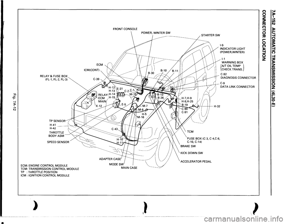
ECM:
ENGINE CONTROL
MODULE
TCM:
TRANSMISSION CONTROL
MODULE
TP :THROTTLE
POSITION
ICM
: IGNITION CONTROL
MODULE
)
ECM
ICM(CONT) FRONT
CONSOLE
MODESW
MAIN
CASE
,}
~H-32
FUSE BOX
(C-3,
C-4,C-8,
C-10,
C-14)
BRAKE
SW
KICK DOWN
SW
ACCELERATOR PEDAL
1-9 INDICATOR LIGHT
(POWER, WINTER) 1-1 WARNING BOX (AfT
OIL
TEMP )
CHECK TRANS.
C-92 DIAGNOSIS CONNECTOR C-9 DATA
LINK CONNECTOR
}
(') 0 2
2 m a ::IJ r-0 (') !4 0 2
" t .... C1l N l> c: a s: !4 n -4 ::IJ l> 2 rA s: c;; rA 0 2 ~ ~ 0 I m
Page 1027 of 1928
... ......,.
AUTOMATIC TRANSMISSION (4L30-E) 7A-155
ON-VEHICLE SERVICE
CHECKING TRANSMISSION FLUID
LEVEL
1. Park the vehicle on level ground.
2. Apply the parking brake.
3. Place the automatic transmission in "Park" and
start the engine.
Allow the engine to idle for
two minutes.
4. With the brakes applied, move the shifter lever
through all the gear ranges, ending in "Park".
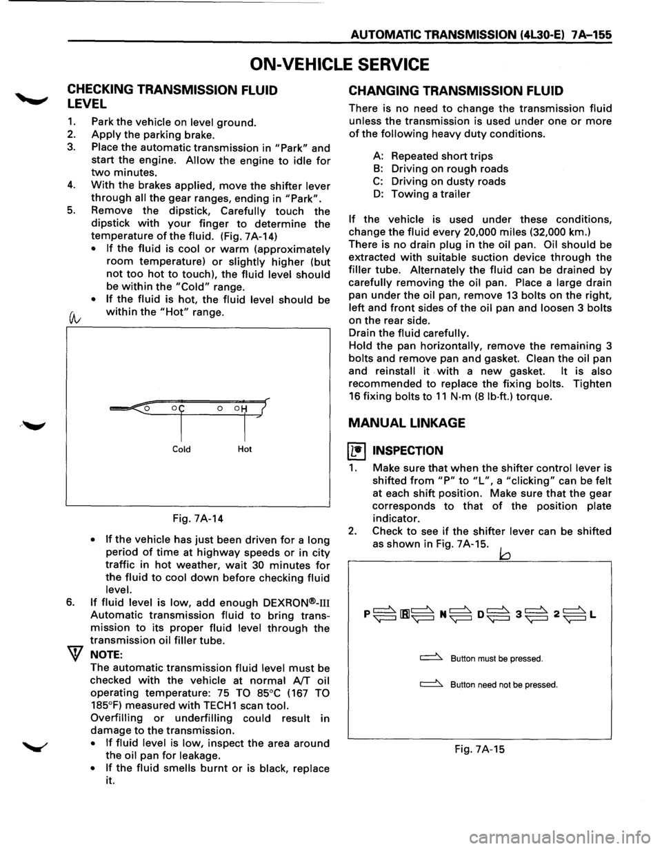
5. Remove the dipstick, Carefully touch the
dipstick with your finger to determine the
temperature of the fluid. (Fig. 7A-14)
• If the fluid is cool or warm (approximately
room temperature) or slightly higher (but
not too hot to touch), the fluid level should
be within the "Cold" range.
• If the fluid is hot, the fluid level should be
(A; within the "Hot" range.
6.
Cold Hot
Fig. 7A-14
• If the vehicle has just been driven for a long
period of time at highway speeds or in city
traffic in hot weather, wait 30 minutes for
the fluid to cool down before checking fluid
level.
If fluid level is low, add enough DEXRON®-m
Automatic transmission fluid to bring trans
mission
to its proper fluid level through the
transmission oil filler tube.
NOTE:
The automatic transmission fluid level must be
checked
with the vehicle at normal AfT oil
operating temperature: 75 TO 85°C (167 TO
185°F)
measured with TECH1 scan tool.
Overfilling or underfilling could result in
damage
to the transmission.
• If fluid level is low, inspect the area around
the oil pan for leakage.
•
If the fluid smells burnt or is black, replace
it.
CHANGING TRANSMISSION FLUID
There is no need to change the transmission fluid
unless the transmission is used under one or more
of the following heavy duty conditions.
A: Repeated
short trips
B: Driving on rough roads
C: Driving on dusty roads
D: Towing a trailer
If the vehicle is used under these conditions,
change the fluid every 20,000 miles (32,000 km.)
There is
no drain plug in the oil pan. Oil should be
extracted
with suitable suction device through the
filler tube. Alternately the fluid can be drained by
carefully removing the oil pan. Place a large drain
pan
under the oil pan, remove 13 bolts on the right,
left and front sides of the oil pan and loosen 3 bolts
on the rear side.
Drain
the fluid carefully.
Hold
the pan horizontally, remove the remaining 3
bolts and remove pan and gasket. Clean the oil pan
and
reinstall it . with a new gasket. It is also
recommended to replace the fixing bolts. Tighten
16 fixing bolts to 11 N·m (8 lb·ft.) torque.
MANUAL LINKAGE
~ INSPECTION
1. Make sure that when the shifter control lever is
shifted
from "P" to "L", a "clicking" can be felt
at each shift position. Make sure that the gear
corresponds
to that of the position plate
indicator.
2. Check to see if the shifter lever can be shifted
as
shown in Fig. 7A-15. jQ
~ Button must be pressed.
~ Button need not be pressed.
Fig. 7A-15
Page 1030 of 1928
7A-158 AUTOMATIC TRANSMISSION (4L30-E)
1. Mode switch cover
2.
Selector lever
• Disconnect selector lever from the mode
switch.
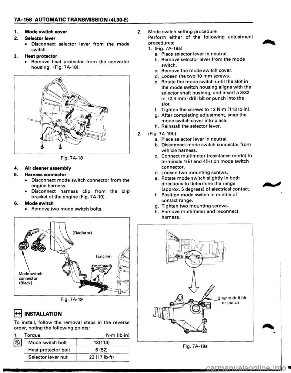
3. Heat protector
• Remove heat protector from the converter
housing. (Fig. 7A-18).
Fig. 7A-18
4. Air cleaner assembly
5. Harness connector
• Disconnect mode switch connector from the
engine harness.
• Disconnect harness clip from the clip
bracket ofthe engine (Fig. 7A-19).
6. Mode switch
• Remove two mode switch bolts.
Mode switch
connector
(Black)
(Radiator)
(Engine)
Fig. 7A-19
I••! INSTALLATION
To install, follow the removal steps in the reverse
order,
noting the following points;
1. Torque
~~~ Mode switch bolt
Heat protector bolt
Selector lever nut
N·m Ob·in)
13(113)
6 (52)
23 ( 17 lb·ft)
2. Mode switch setting procedure
Perform either
of the following adjustment
procedures:
1. (Fig. 7A-19a)
a. Place selector lever in neutral.
b. Remove selector lever from the mode
switch.
c. Remove the mode switch cover.
d. Loosen the
two 10 mm screws.
e. Rotate the mode switch until the slot in
the mode switch housing aligns with the
selector shaft bushing, and insert a 3/32
in. (2.4
mm) drill bit or punch into the
sllot.
f. Tighten the screws to 13 N·m (113 lb·in).
g. After completing adjustment, snap the
mode switch cover into place.
h. Reinstall the selector lever.
2. (Fig. 7 A.-19b)
a. Place selector lever in neutral.
b. Disconnect mode switch connector from
vehicle harness.
c. Connect multimeter (resistance mode) to
terminals 1(E) and 4(H) on mode switch
connector.
d.
Loosen two mounting screws.
e. Rotate mode switch slightly in both
diirections to determine the range
(approx.
5 degrees) of electrical contact.
f. Position
mode switch in middle of
contact range.
g. Tighten
two mounting screws.
h. Remove multimeter and reconnect
harness.
Fig. 7A-19a
..
•
Page 1049 of 1928
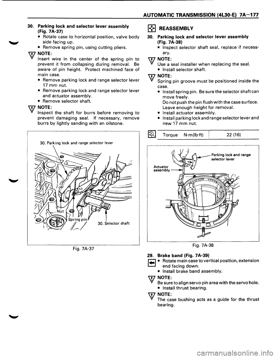
30. Parking lock and selector lever assembly
(Fig. 7A-37)
• Rotate case to horizontal position, valve body
side facing up.
• Remove spring pin, using cutting pliers.
\fl NOTE:
~ Insert wire in the center of the spring pin to
prevent it from collapsing during removal. Be
aware of pin height. Protect machined face of
main case.
• Remove parking lock and range selector lever
17 mm nut.
• Remove parking lock and range selector lever
and actuator assembly.
•
Remove selector shaft.
\fl NOTE:
~ Inspect the shaft for burrs before removing to
prevent damaging seal. If necessary, remove
burrs
by lightly sanding with an oilstone.
30. Parking lock and range selector lever
30. Selector
shaft
Fig. 7A-37
AUTOMATIC TRANSMISSION (4L30-E) 7A-177
1 .. ! .. 1 REASSEMBLY
30. Parking lock and selector lever assembly
(Fig. 7A-38)
• Inspect selector shaft seal, replace if necess
ary.
\fl NOTE:
~ Use a seal installer when replacing the seal.
• Install selector
shaft.
\fl NOTE:
~ Spring pin groove must be positioned inside the
case.
• Install spring pin. Be sure the selector shaft can
move
freely.
Do not push the pin flush with the case surface.
Leave enough
height for removal.
• Install
actuator assembly.
• Install
parking lock and range selector lever and
new 17 mm nut.
~~~ Torque N·m(lb·ft) 22 (16)
Parking lock and range selector lever
Fig. 7A-38
29. Brake band (Fig. 7A-39)
~ • Rotate main case to vertical position, extension
~ end facing down.
• Install brake band assembly.
\fl NOTE:
~ Be sure to align servo pin area with the servo hole.
• Install
thrust bearing.
\fl NOTE:
~ The case bushing acts as a guide for the thrust
bearing.
Page 1159 of 1928
TRANSFER CASE 7D-1
SECTION 70
TRANSFER CASE
w CAUTION:
When fasteners are removed, always reinstall them at the same location from which they were removed. If a
fastener needs
to be replaced, use the correct part number fastener for that application. If the correct part
number is not available, a fastener
of equal size and strength (or stronger) may be used. Fasteners that are
not reused, and those requiring thread locking compound, will
be called out. The correct torque values must
be used when installing fasteners that require torque.
If the above conditions are not followed, parts or
system damage could result.
CONTENTS
General Description ................... 7D-1
Construction . . . . . . . . . . . . . . . . . . . . . . . . . 7D-2
On-Vehicle Service .................... 7D-3
Transfer
Case (A/T) .................. 7D-3
Transfer Rear
Oil Seal ................ 7D-5
Unit Repair ........................... 7D-8
Transfer
Case Assembly (AfT) ........ 7D-8
Transfer Rear
Case Assembly . .
. . . . . 7D-11
Detent, Shift Arm, And
Interlock Pin (Transfer
Case Assembly) . .
. . . . . . . . . . . . . . . . . . 7D-14 Transfer
Case
Assembly . .
. . . . . . . . . .
7D-17
Main Data And Specifications . . . . . . . .
70-29
General
Specifications . .
. . . . . . . . . . . .
70-29
Torque
Specifications ............... 7D-30
Special Tools
........................ 7D-32
GENERAL DESCRIPTION
The transfer case is used to provide a means of
providing power flow to the front axle. The transfer
case also provides a means of disconnecting the front
axle, providing better fuel economy and quieter
operation when the vehicle is driven
on improved
roads where four wheel drive is not required.
In
addition, the transfer case provides an additional gear
reduction when placed in low range, which
is useful
when difficult off-road conditions are encountered. A
floor mounted shift lever is used to select the
operating range. When four wheel drive has been
selected, the four wheel drive indicator light is
designed to come
on when the front axle has been
engaged.
Page 1179 of 1928
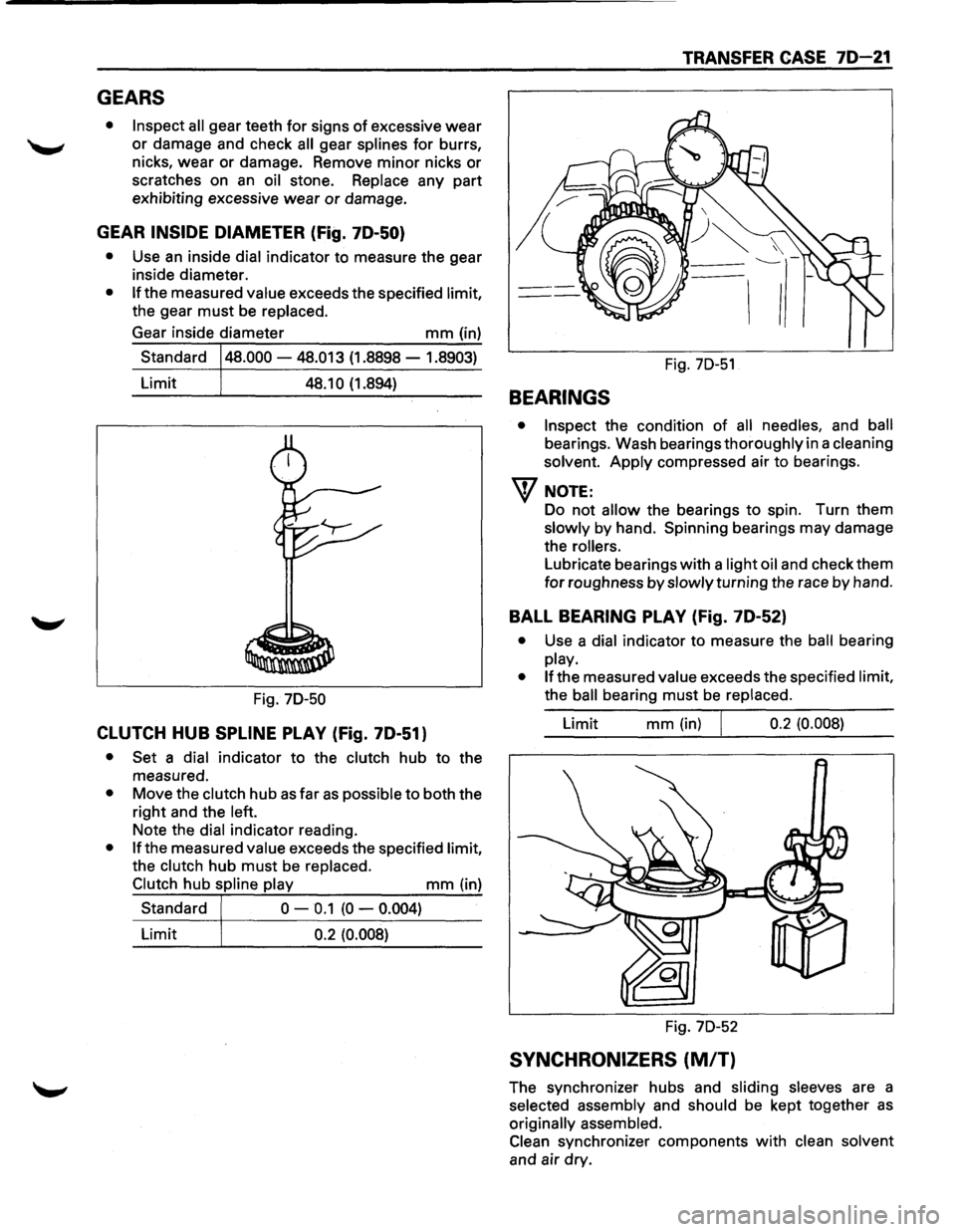
GEARS
• Inspect all gear teeth for signs of excessive wear
'--" or damage and check all gear splines for burrs,
nicks,
wear or damage. Remove minor nicks or
scratches on an oil stone. Replace any part
exhibiting excessive wear or damage.
GEAR INSIDE DIAMETER (Fig. 7D-50}
• Use an inside dial indicator to measure the gear
inside diameter.
• If the measured value exceeds the specified limit,
the gear
must be replaced.
Gear inside diameter
mm (in)
Standard
48.000 -48.013 (1.8898 -1.8903)
Limit 48.1 0 (1.894)
Fig.
70-50
CLUTCH HUB SPLINE PLAY (Fig. 7D-51)
• Set a dial indicator to the clutch hub to the
measured.
• Move the clutch hub as far as possible to both the
right and the left.
Note the dial indicator reading.
• If the measured value exceeds the specified limit,
the clutch hub
must be replaced.
Clutch hub spline play
mm (in)
Standard
0 -0.1 (0 -0.004)
Limit 0.2 (0.008)
TRANSFER CASE 7D-21
I I
Fig. 70-51
BEARINGS
• Inspect the condition of all needles, and ball
bearings. Wash bearings thoroughly in a cleaning
solvent.
Apply compressed air to bearings.
W NOTE:
Do not allow the bearings to spin. Turn them
slowly by hand. Spinning bearings may damage
the
rollers.
Lubricate bearings with a light oil and check them
for roughness by slowly turning the race by hand.
BALL BEARING PLAY (Fig. 7D-52}
• Use a dial indicator to measure the ball bearing
play.
• If the measured value exceeds the specified limit,
the
ball bearing must be replaced.
Limit
mm (in) I 0.2 (0.008)
Fig. 70-52
SYNCHRONIZERS (MIT)
The synchronizer hubs and sliding sleeves are a
selected assembly and should be kept together
as
originally assembled.
Clean synchronizer components
with clean solvent
and air dry.
Page 1191 of 1928

CHASSIS ELECTRICAL 8-1
·SECTION 8
CHASSIS ELECTRICAL
'\f CAUTION: .
When fasteners are removed, always reinstall them at the same location from which they were removed.
If a fastener needs to be replaced, use the correct part number fastener for that application. If the correct
part number fastener is not
available, a fastener of equal size and strength (or stronger) may be used.
Fasteners that are not reused, and those requiring thread
locking compound, will be called out. The correct
torque
values must be used when installing fasteners that require it. If the above conditions are not
followed, parts or system damage could result.
CONTENTS
General Information .................................... 8-2
Notes for Working on Electrical
Items .................................................... 8-2
Symbols and Abbreviations ................. 8-8
Symbols ............................................ 8-8
Abbreviations ................................... 8-9
Parts for Electrical Circuit ..................... 8-10
Wiring ............................................... 8-10
Fuse .................................................. 8-11
Fusible Link ....................................... 8-12
Circuit Breaker ................................... 8-12
Relay ................................................. 8-12
Relay Specifications and
Configurations ................................ 8-13
Diode ................................................. 8-14
Connector ......................................... 8-15
Reading the Circuit Diagram ................ 8-17
Main Data and Specifications .................... 8-19
Bulb Specifications ................................ 8-19
Fuse,
Fusible Link and
Circuit Breaker Location ..................... 8-21
Fuse
Block Circuit .................................. 8-22
Reference Table of Fuse, Fusible
Link and Circuit Breaker ..................... 8-23
Relay Location ....................................... 8-27
Diode Location .......................................
8-28
Grounding Point .................................... 8-29
Reference Table ................................ 8-29
Location ............................................ 8-31
Cable Harness Routing .......................... 8-34
System Repair .............................................. 8-38
Start and Charging ................................ 8-38
Engine Control Module
(ECM) ................................................... 8-47
Headlight and Fog Light ........................ 8-58
Front Side Marker Light, Parking Light,
Taillight, License Plate Light and
Illumination Light .............................. 8-76
Stoplight and Rear Defogger .............. 8-92
Turn Signal Light, Hazard
Warning
Light, Cornering Light,
Backup
Light and Horn ..................... 8-106
Dome Light, Luggage room Light,
Courtesy Light, Map Light,
Seat Belt Switch and
Warning Buzzer ................................. 8-128
Power Door Lock ................................. 8-142
Power
Window .................................... 8-156
Cruise
Control ...................................... 8-172
Anti-Lock Brake
System (ABS) ........... 8-178
Rear
Wheel Anti-Lock Brake
System (RWAL) ................................. 8-185
Transmission
Control Module
(TCM) ................................................. 8-192
A/T Shift Lock ...................................... 8-200
Windshield
Wiper/Washer and
Rear
Wiper/Washer .......................... 8-205
Headlight wiper /washer ..................... 8-232
Audio, Auto Antenna,
Cigarette
Lighter and digital clock ... 8-246
Power Door Mirror ............................... 8-254
Anti-theft System ................................ 8-270
Meter and Warning/Indicator Light ... 8-288
A/T Shift Indicator ............................... 8-336
Heater and
Air Conditioning ............... 8-340
Sun
Roof ............................................... 8-346
Power Seat ........................................... 8-360
Seat
Heater .......................................... 8-37 4
Supplemental Restraint
System (SRS) -AIR BAG ................... 8-382