service ISUZU TROOPER 1995 Workshop Manual
[x] Cancel search | Manufacturer: ISUZU, Model Year: 1995, Model line: TROOPER, Model: ISUZU TROOPER 1995Pages: 1928
Page 1741 of 1928
Supplemental Restraint System 9J-117
SERVICE PRECAUTIONS
CAUTION: WHEN PERFORMING SERVICE ON OR
AROUND SRS COMPONENTS OR SRS WIRING,
FOLLOW
THE PROCEDURES LISTED BELOW TO
TEMPORARILY
DISABLE THE SRS. FAILURE TO
FOLLOW PROCEDURES COULD RESULT IN
POSSIBLE AIR BAG DEPLOYMENT, PERSONAL
INJURY OR OTHERWISE UNNEEDED SRS
REPAIRS.
The DERM in Driver-Passenger SRS can maintain
sufficient voltage to cause a deployment for up to 2
minutes after the ignition switch is turned to
"OFF," the
battery is disconnected, or the fuse powering the DERM
is removed.
Many of the service procedures require removal of the
"AIR BAG" fuse, and disconnection of the inflator
modules from the deployment loop to avoid an accidental
deployment.
If the inflator module is disconnected from
the deployment loop as noted in the "Disabling the
SRS"
procedure that follows, service can begin immediately
without waiting for the 2 minute time period to expire.
DISABLING THE SRS
REMOVAL
• Turn the steering wheel so that the vehicle's wheels
are pointing straight ahead.
• Turn the ignition switch to "OFF"
1. Remove SRS fuse C-21, C-22, C-23 and C-24 from
left dash side lower fuse block.
2. Disconnect yellow
3-way connector at the base of
the steering column.
3. Remove
liP compartment door assembly, Refer to
"Passenger inflator module replacemenf' in section
9J-135.
4. Disconnect yellow 4-way connector behind the liP
compartment door assembly.
NOTE
• With the" AIR BAG" fuse removed and ignition switch
"ON," the "AiR BAG" warning lamp will be "ON." This
is normal operation and does not indicate
an SRS
malfunction.
ENABLING THE SRS
INSTALLATION
Turn ignition switch to "LOCK" and remove key.
1. Connect yellow 4-way connector of passenger
inflator module.
2. Install liP compartment door assembly, Refer to
"Passenger inflator module replacement" in section
9J-3.
3. Connect yellow 3-way connector at the base of the
steering column.
4. Install" AIR BAG" fuse C-21, C-22, C-23 and C-24 to
left dash side lower fuse block.
Tum ignition switch to
"RUN" and verify that the "AIR
BAG"
warning lamp flashes seven times and then turns
"OFF" If it does not operate as described, perform the
"SRS Diagnostic System Check" in section 9J-32.
HANDLING/INSTALLATION/DIAGNOSIS
1. Inflator modules should not be subjected to
temperatures above 65°C(150°F).
2. Discriminating s~nsors, inflator modules, arming
sensors, or DERMs should not be used if they have
been dropped from a height of 1
00 centimeters (3.28
feet) or more.
3. When a discriminating sensor or arming sensor is
replaced, it MUST be oriented with the arrow
on the
sensor pointing toward the front of the vehicle.
It is
very important for the discriminating sensors and
arming sensor to be located flat on the mounting
surface, parallel to the vehicle datum line.
It is
important that the sensor mounting surface is free of
any dirt or other foreign material.
4. Do not apply power to the SRS unless all
components are connected or a diagnostic chart
requests it, as this
will set a diagnostic trouble code.
5. The
"SRS Diagnostic System Check'' must be the
starting point of any SRS diagnostics. The
"SRS
Diagnostic System Check" will verify proper "AIR
BAG" warning lamp operation and will lead you to the
correct chart to diagnose any SRS malfunctions.
Bypassing these procedures may result in extended
diagnostic time, incorrect diagnosis, and incorrect
parts replacements.
INSPECTIONS REQUIRED AFTER ACCI
DENT
CAUTION: CERTAIN SRS COMPONENTS MUST BE
REPLACED AFTER A FRONTAL
CRASH INVOLVING
AIR
BAG DEPLOYMENT.
In all types of accident regardless of "Air Bag"
deployment, visually inspect all the following
components and their points and replace as required:
- Passenger
Inflator Module
- Steering wheel
- SRS coil assembly
- Steering column
- Knee bolster and
Instrument panel mounting
Page 1742 of 1928
9J-118 Supplemental Restraint System
attachments
- Driver seat and belt
- Passenger seat and belt
- Dual Pole Arming
Sensor
-Discriminating Sensors
-DERM
The sensor replacement policy specifies mandatory
replacement of the sensors, after crash involving
AIR
BAG deployment. If AIR BAG has not been deployd,
Replace the sensors
in the area of accident damage only.
The
"area of accident damage" is defined as that area of
the vehicle which is crushed, bent ,or damaged in other
ways. An example might be a front-end collision
in which
the forward portions of the vehicle have contacted
another vehicle, tree, guardrail,etc.
In this example,
1)
If AIR BAG has deployed, All Sensor should be
replaced.
2)
If AIR BAG has not deployed, replace the sensors
in the area of accident damage only.
sensor(s) on the radiator tie bar would require
replacement, since that portion of the vehicle was
damaged in the accident. The Dual Pole Arming Sensor
would not require mandatory replacement. Of course, if
the DERM sets a code and the diagnostic chart leads to
a faulty sensor that was not in the area of accident
damage, that sensor should also be replaced.Sensors
in
the area of accident damage should be replaced even if
those sensors do not appear to be damaged. Do not
attempt to determine whether a sensor is
OK-ALWAYS
replace it if it is in the area of accident damage.Aiso, if a
sensor is
in an area of accident damage,but the SRS has
NOT been deployed,replace the sensor.The sensor
bracket may be slightly bent,wiring may be
damaged, etc., and the sensor might not work properly
in
another collision. Again, do not attempt to determine
whether a sensor is
OK --ALWAYS replace it if it is in
the area of accident damage. Also,
inspect
SRS coil assembly wiring and steering
wheel for any signs of scorching, melting, or damage due
to excessive heat.
If the coil assembly wire or steering ~
wheel is damaged, replace them. The steering column
and wheel must be dimensionally checked to determine
if they are damaged. Refer to
in this Section 3 of this
manual.
Never use
SRS parts from another vehicle. This does not
include remanufactured parts purchased from an
authorized
ISUZU Dealer; they may be used for SRS
repairs.
Do not attempt to repair the forward discriminating
sensors ,the dual pole arming senor, the DERM, the
SRS
coil assembly, the inflator modules, the steering wheel, or
the steering column. Service of these items is
replacement only.
Verify replacement part numbers.
CAUTION: PROPER OPERATION OF THE
SENSORS AND SUPPLEMENTAL RESTRAINT
SYSTEM(SRS)REQUIRES THAT ANY REPAIRS TO
THE VEHICLE STRUCTURE RETURN IT TO ITS
ORIGINAL PRODUCTION CONFIGURATION.
II
Page 1743 of 1928
Supplemental Restraint System 9J-119
DIAGNOSTIC ENERGY RESERVE ,MODULE
WARNING: DURING SERVICE PROCEDURES, BE VERY CAREFUL WHEN HANDLING A SENSOR. NEVER
STRIKE OR
JAR A SENSOR. UNDER SOME CIRCUMSTANCES, IT COULD CAUSE DEPLOYMENT AND
RESULT IN PERSONAL INJURY OR IMPROPER OPERATION OF THE SUPPLEMENTAL RESTRAINT SYSTEM(
SRS
). ALL SENSOR AND MOUNTING BRACKET BOLTS MUST BE CAREFULLY TORQUED TO ASSURE
PROPER OPERATION. NEVER POWER UP THE SRS WHEN ANY SENSOR IS NOT RIGIDLY ATTACHED TO
VEHICLE, SINCE
THE SENSOR COULD BE ACTIVATED WHEN NOT ATTACHED AND COULD RESULT IN
DEPLOYMENT.
WARNING: PROPER OPERATION OF THE SENSORS AND SUPPLEMENTAL RESTRAINT SYSTEM( SRS)
REQUIRES
THAT ANY REPAIRS TO THE VEHICLE STRUCTURE RETURN IT TO ITS ORIGINAL PRODUCTION
CONFIGURATION.
DEPLOYMENT (CURRENT CODE 51 )OR ANY VISIBLE DAMAGE TO SENSOR AND/OR
THEIR MOUNTING BRACKETS REQUIRES REPLACEMENT, NOT REPAI~. PROPER OPERATION OF A
SENSOR ALSO REQUIRES THAT SENSOR BE RIGIDLY BOLTED TO THE VEHICLE STRUCTURE.THE ARROW
ON THE SENSOR MUST BE POINTING TOWARD THE FRONT OF THE VEHICLE. FAILURE TO OBSERVE
THESE PRECAUTIONS CAN RESULT IN IMPROPER SRS OPERATION AND POSSIBLE LACK OF
SUPPLEMENTAL RESTRAINT PROTECTION FOR THE DRIVER AND PASSENGER DURING AN ACCIDENT
IMPACT.
All
sensors are specifically calibrated and are keyed to the sensor location and SRS wiring harness. Caution should
be used to ensure proper location of the sensors. The keying of the sensor to their locations and wiring harness
connectors should never be modified in the filed.
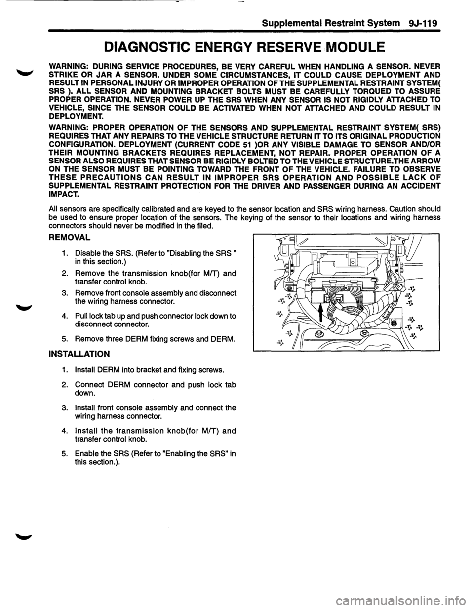
REMOVAL
1. Disable the SRS. (Refer to "Disabling the SRS "
in this section.)
2. Remove the transmission knob(for MIT) and
transfer control knob.
3. Remove front console assembly and disconnect
the wiring harness connector.
4. Pull lock tab up and push connector lock down to
disconnect connector.
5. Remove three DERM fixing screws and DERM. •d ...........
INSTALLATION
1. Install DERM into bracket and fixing screws.
2. Connect DERM connector and push lock tab
down.
3. Install front console assembly and connect the
wiring harness connector.
4. Install the transmission knob(for MIT) and
transfer control knob.
5. Enable the SRS (Refer to "Enabling the SRS" in
this section.).
Page 1744 of 1928
9J-120 Supplemental Restraint System
DISCRIMINATING SENSOR -FORWARD SENSOR LH
WARNING: DURING SERVICE PROCEDURES, BE VERY CAREFUL WHEN HANDLING A SENSOR. NEVER ~
STRIKE OR JAR A SENSOR. UNDER SOME CIRCUMSTANCES, IT COULD CAUSE DEPLOYMENT AND
RESULT IN PERSONAL INJURY OR IMPROPER OPERATION OF THE SUPPLEMENTAL RESTRAINT SYSTEM(
SRS
). ALL SENSOR AND MOUNTING BRACKET BOLTS MUST BE CAREFULLY TORQUED TO ASSURE
PROPER OPERATION. NEVER POWER UP THE SRS WHEN ANY SENSOR IS NOT RIGIDLY ATTACHED TO
VEHICLE, SINCE
THE SENSOR COULD BE ACTIVATED WHEN NOT ATTACHED AND COULD RESULT IN
DEPLOYMENT.
WARNING: PROPER OPERATION OF THE SENSORS AND SUPPLEMENTAL RESTRAINT SYSTEM( SRS)
REQUIRES
THAT ANY REPAIRS TO THE VEHICLE STRUCTURE RETURN IT TO ITS ORIGINAL PRODUCTION
CONFIGURATION.
DEPLOYMENT (CURRENT CODE 51 )OR ANY VISIBLE DAMAGE TO SENSOR AND/OR
THEIR MOUNTING BRACKETS REQUIRES REPLACEMENT, NOT REPAIR. PROPER OPERATION OF A
SENSOR ALSO REQUIRES THAT SENSOR BE RIGIDLY BOLTED TO THE VEHICLE STRUCTURE. THE ARROW
ON
THE SENSOR MUST BE POINTING TOWARD THE FRONT OF THE VEHICLE. FAILURE TO OBSERVE
THESE PRECAUTIONS CAN RESULT IN IMPROPER SRS OPERATION AND POSSIBLE LACK OF
SUPPLEMENTAL RESTRAINT PROTECTION FOR THE DRIVER AND PASSENGER DURING AN ACCIDENT
IMPACT.
All
sensors are specifically calibrated and are keyed to the sensor location and SRS wiring harness. Caution should
be used to ensure proper location of the sensors. The keying of the sensor to their locations and wiring harness
connectors
should never be modified in the filed.
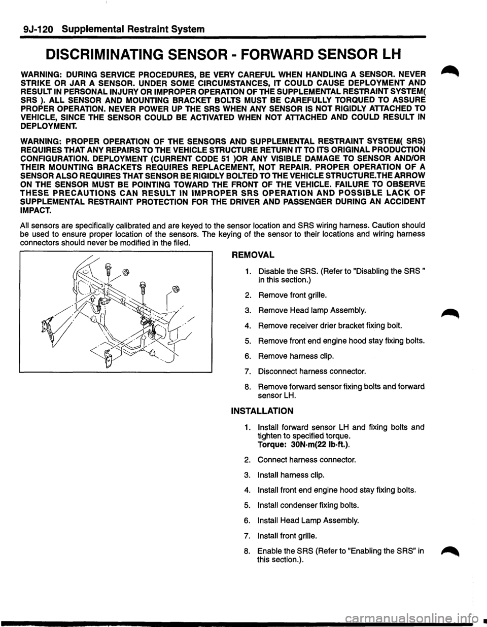
REMOVAL
1. Disable the SRS. (Refer to "Disabling the SRS "
in this section.)
2. Remove front grille.
3. Remove Head lamp Assembly.
4. Remove receiver drier bracket fixing bolt.
5. Remove front end engine hood stay fixing bolts.
6. Remove harness clip.
7. Disconnect harness connector.
8. Remove forward sensor fixing bolts and forward
sensor
LH.
INSTALLATION
1. Install forward sensor LH and fixing bolts and
tighten to specified torque.
Torque:
30N·m(221b·ft.).
2. Connect harness connector.
3. Install harness clip.
4. Install front end engine hood stay fixing bolts.
5. Install condenser fixing bolts.
6. Install Head Lamp Assembly.
7. Install front grille.
8. Enable the SRS (Refer to "Enabling the SRS" in
this section.). ~
•
Page 1745 of 1928
Supplemental Restraint System 9J-121
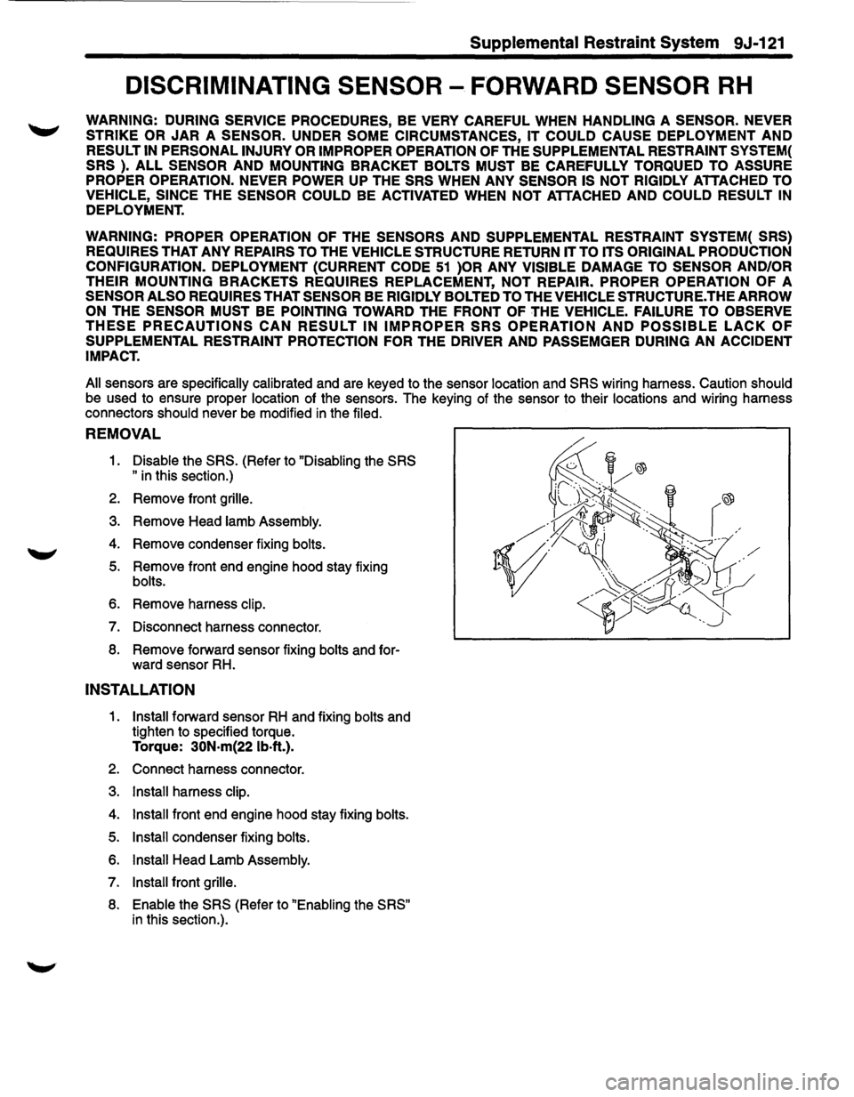
DISCRIMINATING SENSOR -FORWARD SENSOR RH
WARNING: DURING SERVICE PROCEDURES, BE VERY CAREFUL WHEN HANDLING A SENSOR. NEVER
STRIKE OR JAR A SENSOR. UNDER SOME CIRCUMSTANCES, IT COULD CAUSE DEPLOYMENT AND
RESULT IN PERSONAL INJURY OR IMPROPER OPERATION OF THE SUPPLEMENTAL RESTRAINT SYSTEM(
SRS ). ALL SENSOR AND MOUNTING BRACKET BOLTS MUST BE CAREIFULLY TORQUED TO ASSURE
PROPER OPERATION. NEVER POWER UP
THE SRS WHEN ANY SENSOR IS NOT RIGIDLY ATTACHED TO
VEHICLE, SINCE
THE SENSOR COULD BE ACTIVATED WHEN NOT ATTACHED AND COULD RESULT IN
DEPLOYMENT.
WARNING: PROPER OPERATION
OF THE SENSORS AND SUPPLEMENTAL RESTRAINT SYSTEM( SRS)
REQUIRES
THAT ANY REPAIRS TO THE VEHICLE STRUCTURE RETURN IT TO ITS ORIGINAL PRODUCTION
CONFIGURATION. DEPLOYMENT (CURRENT CODE
51 )OR ANY VISIBLE DAMAGE TO SENSOR AND/OR
THEIR
MOUNTING BRACKETS REQUIRES REPLACEMENT, NOT REPAIR. PROPER OPERATION OF A
SENSOR ALSO REQUIRES THAT SENSOR BE RIGIDLY BOLTED TO THE VEHICLE STRUCTURE. THE ARROW
ON
THE SENSOR MUST BE POINTING TOWARD THE FRONT OF THE VEHICLE. FAILURE TO OBSERVE
THESE PRECAUTIONS CAN RESULT IN IMPROPER SRS OPERATION AND POSSIBLE LACK OF
SUPPLEMENTAL RESTRAINT PROTECTION FOR THE DRIVER AND PASSEMGER DURING AN ACCIDENT
IMPACT.
All
sensors are specifically calibrated and are keyed to the sensor location and SRS wiring harness. Caution should
be used to ensure proper location of the sensors. The keying of the sensor to their locations and wiring harness
connectors
should never be modified in the filed.
REMOVAL
1. Disable the SRS. (Refer to "Disabling the SRS
"
in this section.)
2. Remove front grille.
3. Remove Head lamb Assembly.
4. Remove condenser fixing bolts.
5. Remove front end engine hood stay fixing
bolts.
6. Remove harness clip.
7. Disconnect harness connector.
8. Remove forward sensor fixing bolts and for
ward sensor RH.
INSTALLATION
1. Install forward sensor RH and fixing bolts and
tighten to specified torque.
Torque: 30N·m{22 lb·ft.).
2. Connect harness connector.
3. Install harness clip.
4. Install front end engine hood stay fixing bolts.
5. Install condenser fixing bolts.
6. Install Head Lamb Assembly.
7. Install front grille.
8. Enable the SRS (Refer to "Enabling the SRS"
in this section.).
Page 1746 of 1928
9J-122 Supplemental Restraint System
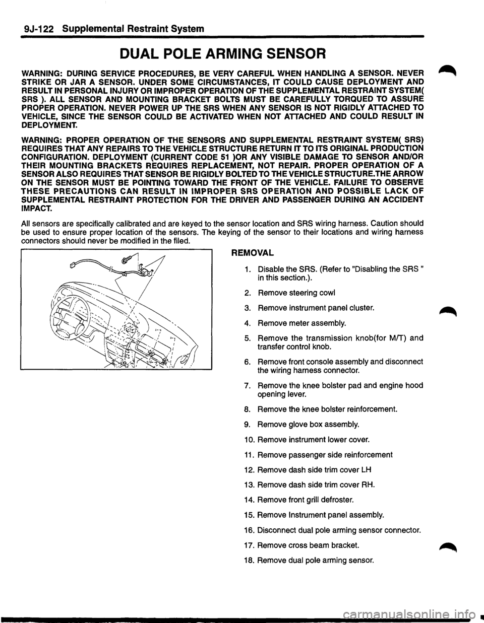
DUAL POLE ARMING SENSOR
WARNING: DURING SERVICE PROCEDURES, BE VERY CAREFUL WHEN HANDLING A SENSOR. NEVER ~
STRIKE OR JAR A SENSOR. UNDER SOME CIRCUMSTANCES, IT COULD CAUSE DEPLOYMENT AND
RESULT IN PERSONAL INJURY OR IMPROPER OPERATION OF THE SUPPLEMENTAL RESTRAINT SYSTEM(
SRS
). ALL SENSOR AND MOUNTING BRACKET BOLTS MUST BE CAREFULLY TORQUED TO ASSURE
PROPER OPERATION. NEVER POWER
UP THE SRS WHEN ANY SENSOR IS NOT RIGIDLY ATTACHED TO
VEHICLE, SINCE
THE SENSOR COULD BE ACTIVATED WHEN NOT ATTACHED AND COULD RESULT IN
DEPLOYMENT.
WARNING: PROPER OPERATION OF THE SENSORS AND SUPPLEMENTAL RESTRAINT SYSTEM( SRS)
REQUIRES
THAT ANY REPAIRS TO THE VEHICLE STRUCTURE RETURN IT TO ITS ORIGINAL PRODUCTION
CONFIGURATION.
DEPLOYMENT (CURRENT CODE 51 )OR ANY VISIBLE DAMAGE TO SENSOR AND/OR
THEIR MOUNTING
BRACKETS REQUIRES REPLACEMENT, NOT REPAIR. PROPER OPERATION OF A
SENSOR ALSO REQUIRES THAT SENSOR BE RIGIDLY BOLTED TO THE VEHICLE STRUCTURE. THE ARROW
ON
THE SENSOR MUST BE POINTING TOWARD THE FRONT OF THE VEHICLE. FAILURE TO OBSERVE
THESE PRECAUTIONS CAN RESULT IN IMPROPER SRS OPERATION AND POSSIBLE LACK OF
SUPPLEMENTAL RESTRAINT PROTECTION FOR THE DRIVER AND PASSENGER DURING AN ACCIDENT
IMPACT.
All
sensors are specifically calibrated and are keyed to the sensor location and SRS wiring harness. Caution should
be used to ensure proper location of the sensors. The keying of the sensor to their locations and wiring harness
connectors should never be modified
in the filed.
REMOVAL
1. Disable the SRS. (Refer to "Disabling the SRS "
in this section.).
2. Remove steering
cowl
3. Remove instrument panel cluster. ~
4. Remove meter assembly.
5. Remove the transmission knob(for Mff) and
transfer control knob.
6. Remove front console assembly and disconnect
the wiring harness connector.
7. Remove the knee bolster pad and engine hood
opening lever.
8. Remove the knee bolster reinforcement.
9. Remove glove box assembly.
10. Remove instrument lower cover.
11. Remove passenger side reinforcement
12. Remove dash side trim cover
LH
13. Remove dash side trim cover RH.
14. Remove front grill defroster.
15. Remove
Instrument panel assembly.
16. Disconnect
dual pole arming sensor connector.
17. Remove cross beam bracket.
18. Remove
dual pole arming sensor.
II
Page 1759 of 1928
BODY 10-1
SECTION 10
BODY
\V CAUTION : When fasteners are removed, always reinstall them at the same location from which they
were removed. If a fastener needs to be replaced, use the correct part number fastener for
that application. If the correct part number fastener is not available, a fastener of equal size
and strength (or stronger)
may be used. Fasteners must be used when installing fasteners
that require it. If the above conditions are not followed, parts of system damage could result.
CONTENTS
General Description ................. 10-2 Front Door Weatherstrip ......... 10-53
On-Vehicle Service .................. 10-3 Rear Door Weatherstrip .......... 10-54
Body Dimension .................. 10-3 Front Door Seal Finisher ......... 10-54
Upper Body .................... 10-3 Rear Door Seal Finisher .......... 10-54
Front Section ................... 10-7 Door Mirror .................... 10-55
Room Section .................. 10-9 Body Side ....................... 10-56
Rear Section ................... 10-14 Interior Trim Panels ............. 10-56
Side Body ..................... 10-16 Center Pillar and Roof Side Trim
Window Glass .................. 10-19 Cover (L·W·B only) .............. 10-61
Front End ........................ 10-23 Roof Side Trim Cover (S·W·B only) . 10-62
Dash Side Trim Panel ............ 10-23 Front Pillar Trim Cover ........... 10-63
Assist Grip ..................... 10-23 Center Pillar Assist Grip .......... 10-63
Consoles ...................... 10-24 Assist Grip ..................... 10-63
Instrument Panel Assembly ....... 10-25 Fuel Filler lid Opener Cable ....... 10-64
Cross Beam Assembly ........... 10-30 Fuel Filler Door ................. 10-65
Doors ........................... 10-32 Rocker Protector (Without Wheel
Front Door Assembly ............ 10-32 Opening Extension) ............. 10-66
Rear Door Assembly ............. 10-32 Wheel Opening Extension
Door Strikers ................... 10-33 and Rocker Protector Assembly ... 10-67
Door Check Arm Assembly Mud Flaps (With Wheel Opening
(Front & Rear) .................. 10-34 Extension) ..................... 10-69
Front Door Trim Panel ........... 10-35 Ventilation Assembly ............ 10-70
Rear Door Trim Panel ............ 10-38 Quarter Flipper Glass Assembly
Door Wood Panel Assembly ...... 10-40 (S·W·B) ........................ 10-71
Front Window Regulator, Glass Rear End ........................ 10-72
and Glass Run .................. 10-41 Tailgate Assembly (LH) .......... 10-72
Rear Window Regulator and Tailgate Assembly (RH) .......... 10-73
Glass ......................... 10-43 Tailgate Strikers ................ 10-75
Front Door Lock Assembly ....... 10-45 Tailgate Trim Panel (LH) .......... 10-75
Rear Door Lock Assembly ........ 10-46 Tailgate Trim Panel (RH) .......... 10-76
Front Outside Handle and Tailgate Lock Assembly (LH) ...... 10-77
Door Lock Cylinder .............. 10-47 Tailgate Lock Assembly (RH) ...... 10-78
Rear Outside Handle ............. 10-48 Tailgate Inside Lock Knob ........ 10-79
Rear Door Fixed Glass and Tailgate Outside Handle and/or
Glass Run ...................... 10-49 Tailgate Lock Cylinder ........... 10-80
Door Inside Lock Knob ........... 10-50 Tailgate Stopper Assembly ....... 10-81
Door Inside Handle .............. 10-50 Tailgate Dove-tail ............... 10-81
Rear Door Inside Lock Knob Link .. 10-51 Tailgate Dove-tail Strikers ........ 10-82
Front Door Sash Moulding ....... 10-51 Tailgate Frame Cover (LH) ........ 10-82
Rear Door Moulding ............. 10-52 Tailgate Frame Cover (RH) ........ 10-83
Front Door Waist Seal ........... 10-52 Tailgate Sash Trim Cover ......... 10-83
Rear Door Waist Seal ............ 10-53 Tailgate Outer Weatherstrip ...... 10-84
Page 1761 of 1928
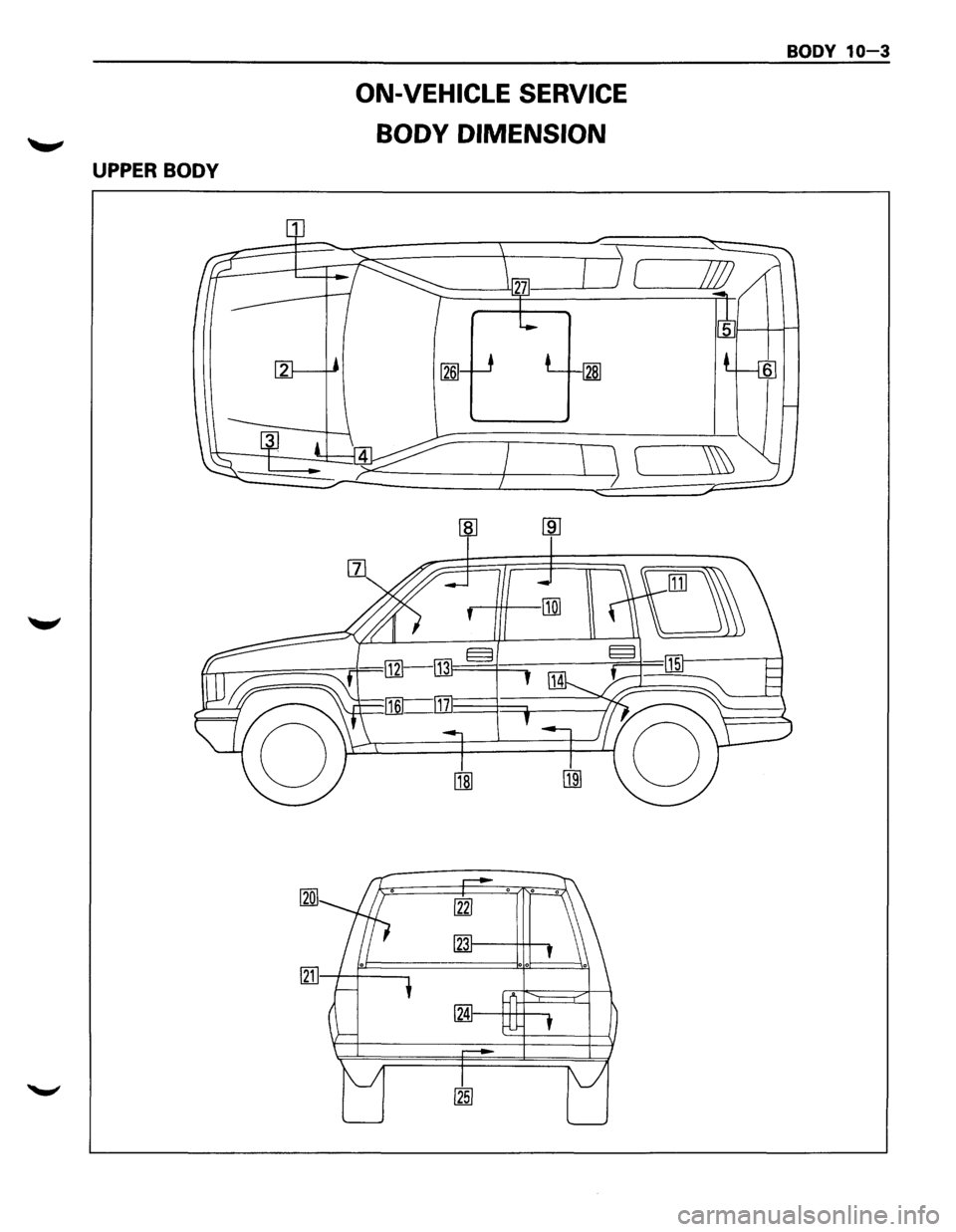
UPPER BODY
ON-VEHICLE SERVICE
BODY DIMENSION
BODY 10-3
Page 1893 of 1928
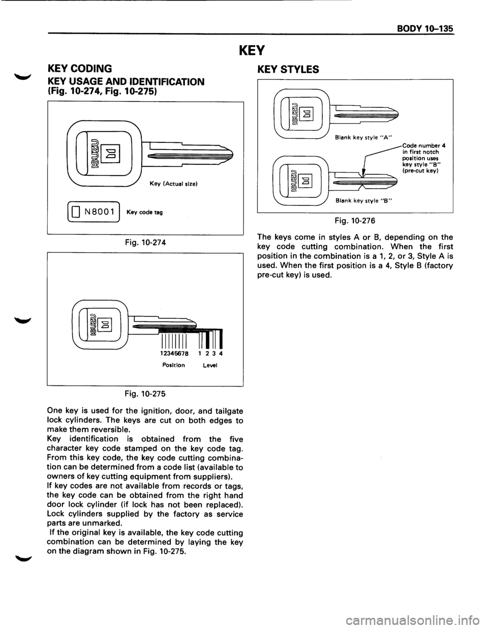
BODY 1Q-135
KEY
KEY CODING
KEY USAGE AND IDENTIFICATION
(Fig. 10-274, Fig. 10-275)
I
Key (Actual size)
( 0 N8001) Keycodetag
Fig. 10-274
12345678 1 2 3 4
Position Level
Fig. 10-275
One
key is used for the ignition, door, and tailgate
lock cylinders.
The keys are cut on both edges to
make them reversible.
Key identification is obtained from the five
character key code stamped on
the key code tag.
From
this key code, the key code cutting combina
tion can be determined from a code list (available to
owners of key cutting equipment from suppliers).
If key codes are not available from records or tags,
the key code can be obtained
from the right hand
door lock cylinder (if lock has not been replaced).
Lock cylinders supplied by the factory as service
parts are unmarked.
If the original key is available, the key code cutting
combination can be determined by laying the key
on the diagram
shown in Fig. 10-275.
KEY STYLES
Blank key style "A"
Blank key style "B"
Fig. 10-276
Code number 4
in first notch position uses key style "B" (pre-cut key)
The keys come in styles A or 8, depending on the
key code cutting combination. When the
first
position in the combination is a 1, 2, or 3, Style A is
used. When the
first position is a 4, Style 8 (factory
pre-cut key) is used.