service ISUZU TROOPER 1995 Workshop Manual
[x] Cancel search | Manufacturer: ISUZU, Model Year: 1995, Model line: TROOPER, Model: ISUZU TROOPER 1995Pages: 1928
Page 1159 of 1928
TRANSFER CASE 7D-1
SECTION 70
TRANSFER CASE
w CAUTION:
When fasteners are removed, always reinstall them at the same location from which they were removed. If a
fastener needs
to be replaced, use the correct part number fastener for that application. If the correct part
number is not available, a fastener
of equal size and strength (or stronger) may be used. Fasteners that are
not reused, and those requiring thread locking compound, will
be called out. The correct torque values must
be used when installing fasteners that require torque.
If the above conditions are not followed, parts or
system damage could result.
CONTENTS
General Description ................... 7D-1
Construction . . . . . . . . . . . . . . . . . . . . . . . . . 7D-2
On-Vehicle Service .................... 7D-3
Transfer
Case (A/T) .................. 7D-3
Transfer Rear
Oil Seal ................ 7D-5
Unit Repair ........................... 7D-8
Transfer
Case Assembly (AfT) ........ 7D-8
Transfer Rear
Case Assembly . .
. . . . . 7D-11
Detent, Shift Arm, And
Interlock Pin (Transfer
Case Assembly) . .
. . . . . . . . . . . . . . . . . . 7D-14 Transfer
Case
Assembly . .
. . . . . . . . . .
7D-17
Main Data And Specifications . . . . . . . .
70-29
General
Specifications . .
. . . . . . . . . . . .
70-29
Torque
Specifications ............... 7D-30
Special Tools
........................ 7D-32
GENERAL DESCRIPTION
The transfer case is used to provide a means of
providing power flow to the front axle. The transfer
case also provides a means of disconnecting the front
axle, providing better fuel economy and quieter
operation when the vehicle is driven
on improved
roads where four wheel drive is not required.
In
addition, the transfer case provides an additional gear
reduction when placed in low range, which
is useful
when difficult off-road conditions are encountered. A
floor mounted shift lever is used to select the
operating range. When four wheel drive has been
selected, the four wheel drive indicator light is
designed to come
on when the front axle has been
engaged.
Page 1161 of 1928
TRANSFER CASE 70-3
ON-VEHICLE SERVICE
TRANSFER CASE (A/T)
5
<;J---5 6
7
' 8
9
~
10
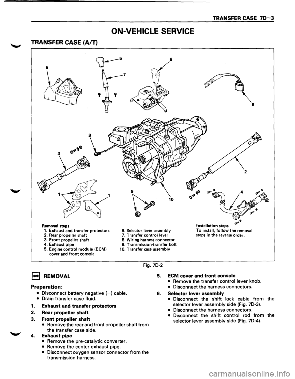
Removal steps Installation steps
1. Exhaust and transfer protectors 6. Selector lever
assembly To
install, follow the removal
steps in the reverse order.
2. Rear propeller shaft 7.
Transfer control lever
3. Front propeller shaft 8.
Wiring harness connector
4. Exhaust pipe 9. Transmission-transfer bolt
5. Engine control module
(ECM)
cover and front console 10.
Transfer case assembly
Fig. 7D-2
l••l REMOVAL
Preparation:
• Disconnect battery negative (-) cable.
•
Drain transfer case fluid.
1. Exhaust and transfer protectors
2. Rear propeller shaft
3. Front propeller shaft
• Remove the rear and front propeller shaft from
the transfer case side.
4. Exhaust pipe
• Remove the pre-catalytic converter.
• Remove the center exhaust pipe.
• Disconnect oxygen sensor connector from the
transmission harness.
5. ECM cover and front console
• Remove the transfer control lever knob.
• Disconnect the harness connectors.
6. Selector lever assembly
• Disconnect the shift lock cable from the
selector lever assembly side (Fig. 7D-3).
• Disconnect the harness connectors.
• Disconnect the shift control rod from the
selector lever assembly side (Fig. 7D-4).
Page 1368 of 1928
8 -178 CHASSIS ELECTRICAL
ANTI-LOCK BRAKE SYSTEM (ABS)
GENERAL DESCRIPTION
The circuit consists of the starter switch, stoplight switch (vehicle w/o cruise control), brake switch (vehicle
with cruise control), hydraulic unit, electronic brake control module, wheel speed sensor, G sensor, ABS and
4WD indicator, 4WD switch and data link connector.
When the service brake is applied while in the running mode,
the EBCM (Electronic Brake Control Module)
judges
which wheel is about to lock by using the wheel rotation speed signals sent from the four ABS speed
sensors at the
front and rear wheels. And the brake fluid pressure applied to the four wheels is controlled by
a hydraulic unit to prevent the wheels from locking.
Based on the wheel rotation speed signals
input from the ABS sensor, the EBCM sends out signals to the
solenoid valve in the hydraulic unit
to increase, maintain or decrease the brake fluid pressure. The solenoid
valve uses this signal
to control the fluid pressure which is applied to the calipers of the disk brakes of the
front wheels. (The system also controls at the same time the fluid pressure applied to the rear wheels.)
• EBCM (Electronic brake control module)
The EBCM uses the signals sent from the speed sensor to control the operation of the hydraulic unit.
When any malfunction occurs in the ABS, the
EBCM activates the fail-safe fuction while turning on the
ABS warning light.
• Hydraulic unit
The hydraulic unit consists of the motor, plunger pump, solenoid valve, and fluid pressure control
valves. The exterior
of the unit has a relay box consisting of the motor relay and valve relay. Three
solenoid valves, the
two of which are provided at the front wheels and the one at the rear wheels, control
the fluid pressure
of these wheels.
• Speed sensor
The speed sensor consists of the sensor and the rotor. It sends the EBCM the AC voltage generated by
the rotation of the rotor as the vehicle speed signal. ~
• G-sensor
The G-sensor, installed inside the center console, sends out signals to the EBCM by detecting the
decelerating speed
of the vehicle.
• ABS warning light
The ABS warning light in the instrument panel, lights up when any malfunction occurs in the ABS. It also
lights up
with the starter key at the "ON" position, as a self-check.
Refer
to Section 5A4, "ANTI-LOCK BRAKE SYSTEM" for detail.
II
Page 1375 of 1928
CHASSIS ELECTRICAL 8-185
REAR WHEEL ANTI-LOCK BRAKE SYSTEM (RWAL)
GENERAL DESCRIPTION
The circuit consists of the starter switch, stoplight switch (vehicle w/o cruise control), brake switch (vehicle
w/cruise control). RWAL controller, RWAL speed sensor, RWAL valve, brake differential switch, 4WD switch,
parking brake
SW, indicator light (RWAL, 4WD, BRAKE), and test connector.
In this system, when the service brake is applied the RWAL controller judges the wheel rotation difference
signals which have been sent from the RWAL speed sensor at the rear axle differential. The anti-lock valves
control
the brake fluid pressure which is applied to the rear wheels to prevent the wheels from locking.
When starting the engine, the RWAL indicator in the instrument panel lights up at the same time as the brake
indicator
to inform the driver that the system is operating normally. (The light goes off after two seconds.)
Refer
to Section 5A3, "RWAL (REAR WHEEL ANTI-LOCK BRAKE SYSTEM)" for detail.
Page 1509 of 1928
![ISUZU TROOPER 1995 Workshop Manual (1!] ON-VEHICLE SERVICE
"-"" Check the meter display accuracy and the operation
of the odometer with the speedometer tester.
\f CAUTION:
Inappropriate tire inflation may affect the accu
rac](/img/61/57183/w960_57183-1508.png "ISUZU TROOPER 1995 Workshop Manual (1!] ON-VEHICLE SERVICE
\"-\"\" Check the meter display accuracy and the operation
of the odometer with the speedometer tester.
\f CAUTION:
Inappropriate tire inflation may affect the accu
rac")
(1!] ON-VEHICLE SERVICE
"-"" Check the meter display accuracy and the operation
of the odometer with the speedometer tester.
\f CAUTION:
Inappropriate tire inflation may affect the accu
racy
of the odometer.
(To
conductthis test, refer to the tester manufac
turer's instruction manual.)
IGN GND
SEN
CHASSIS ELECTRICAL 8-319
(MPH)
Tester display speed Meter
display permissible
level
20 18.3-21.7
40 38.3-41.7
60 58.3-61.7
80 78.8-82.8
100 98.8-102.8
120 118.5-123.1
NOTE: Since the meter display permissible levels
above are specifications solely
for the
meter,
they are to be used as reference
values when conducting on-vehicle service.
~ INDIVIDUAL INSPECTION
I t!!.l Remove the speedometer from the meter
assembly and measure the resistance and the
current consumption between each terminal.
(Fig. 8-347)
Replace the speedometer
when the result of
inspection is found abnormal.
Resistance value
Red(+) Black(-) Black(-) Red(+)
IGN GND IGN GND IGN-GND 00 30.6-37.4k
SEN GND SEN GND SEN-GND 28.8-35.2k 00
4P GND 4P GND 4P-GND 13.5 -16.5k 00
Note: Use the
analog type circuit tester (range: x 1k)
Current value
Terminal
symbol
IGN-GND
~ 8
Current
consumption
85 ± 15mA Remarks
(when
12 ± 1V No signal input
applied)
Note: 1. Use the analog type circuit tester.
2. Since the current consumption fluctuates
when the source voltage varies, check
to
be sure that the voltage applied is 12V ± 1 V.
Fig. 8-347
Page 1511 of 1928
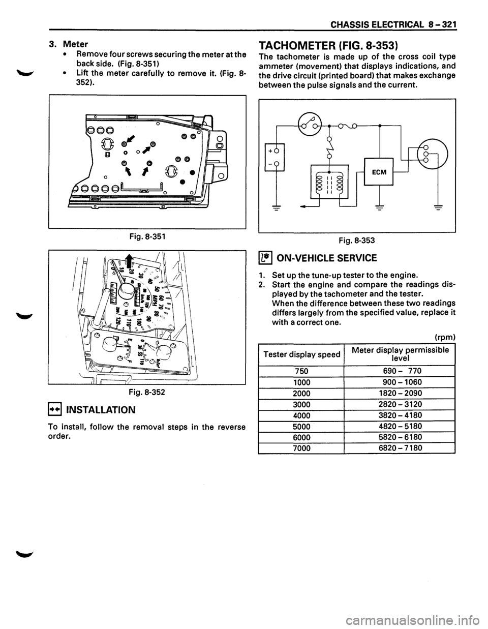
3. Meter
• Remove four screws securing the meter at the
back side. (Fig.
8-351)
• Lift the meter carefully to remove it. (Fig. 8-
352).
0
q;J"' 0
0 0 0,
0 0
0 I
Fig. 8-351
Fig. 8-352
E) INSTALLATION
00
0
To install, follow the removal steps in the reverse
order.
CHASSIS ELECTRICAL 8-321
TACHOMETER (FIG. 8-353)
The tachometer is made up of the cross coil type
ammeter (movement) that displays indications, and
the drive circuit (printed board)
that makes exchange
between the
pulse signals and the current.
Fig.
8-353
(1!1 ON-VEHICLE SERVICE
1. Set up the tune-up tester to the engine.
2. Start the engine and compare the readings dis
played by the tachometer and the tester.
When the difference between these
two readings
differs
largely from the specified value, replace it
with a correct one.
(rpm)
Tester
display speed Meter
display permissible level
750 690-770
1000
900-1060
2000 1820-2090
3000 2820-3120
4000 3820-4180
5000 4820-5180
6000 5820-6180
7000 6820-7180
Page 1585 of 1928
---------------~-~---
CRUISE CONTROL 9B-1
SECTION 98
CRUISE CONTROL
CONTENTS
General description ................................ .
Parts location .......................................... .
Circuit diagram ....................................... .
Diagnosis ................................................. .
On-vehicle service ................................. ..
Brake switch adjustment ................ ..
Clutch switch adjustment ................ .
Actuator
cable adjustment .............. .
Starter switch ................................... .
Cruise control main switch .............. .
GENERAL DESCRIPTION
98-1
9B-3
98-4
9B-7
98-28
9B-28
9B-28
9B-28
9B-28
9B-30 Cruise
control
switch
(combination switch) ........................ 98-31
Cruise control unit .......................... ... 9B-32
Pump
& actuator .................. .............. 9B-34
Brake switch ....................................... 9B-36
Clutch switch .............................. ....... 9B-36
Mode switch .. .. .. .. .. .. .. .. .. .. .. .. .. .. .. .. .. .. .. . 9B-37
Vehicle speed sensor
(incorporated in speedometer) ......... 9B-38
Diode
.. .. .. .. .. .. . .. .. .. .. .. . .. .. .. .. .. .. .. .. .. .. . .. .. .. 9B-38
Cruise control main relay .................. 9B-39
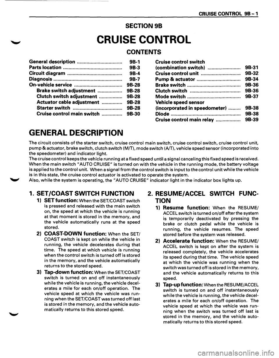
The circuit consists of the starter switch, cruise control main switch, cruise control switch, cruise control unit,
pump &actuator, brake switch, clutch switch (M/T), mode switch (A/T), vehicle speed sensor (incorporated into
the speedometer) and indicator light.
The cruise control keeps
the vehicle running at a fixed speed until a signal canceling this fixed speed is received.
When the main switch "AUTO CRUISE" is turned on with the vehicle in the running mode, the battery voltage
is applied
to the control unit. When a signal from the control switch is input to the control unit while the vehicle
is in this state, the cruise control actuator is activated to operate the system .
.._, Also, while the system is operating, the "AUTO CRUISE" indicator light in the indicator box lights up.
1. SET /COAST SWITCH FUNCTION
1) SET function: When the SET/COAST switch
is pressed and released
with the main switch
on, the speed at
which the vehicle is running
at that moment is stored in the memory, and
the vehicle
automatically runs at the speed
stored.
2) COAST-DOWN function: When the SET/
COAST switch is kept on while the vehicle in
running, the vehicle decelerates
during that
time. The speed at which vehicle is running
when the control switch is turned off is stored
in the
memory, and the vehicle automatically
returns
to the stored speed.
3) Tap-down function: When the SET/COAST
switch is turned on and off instantaneously
while the vehicle is running, the vehicle decel
erates a mile for each on/off operation. The
vehicle speed at
which the vehicle was run
ning when the SET/COAST was turned off last
is stored in the
memory, and the vehicle auto
matically returns to this stored speed.
2. RESUME/ ACCEL SWITCH FUNC
TION
1) Resume function: When the RESUME/
ACCEL switch is turned
on/off after the system
is
temporarily deactivated by pressing the
brake or clutch pedal while the vehicle is
running,
the vehicle resumes. The speed
stored before the system
was released.
2) Accelerate function: When the RESUME/
ACCEL switch is kept on after the system is
released completely, the vehicle accelerates
its speed
during that time. The vehicle speed
at
which the vehicle was running when the
switch
was turned off is stored in the memory,
and the vehicle automatically returns to this
speed.
3) Tap-up function: When the RESU ME/ACCEL
switch is
turned on and off instantaneously
while the vehicle is running, the vehicle decel
erates a mile for each on/off operation. The
vehicle speed at
which the vehicle was run
ning when the switch was turned off last is
stored in the
memory, and the vehicle auto
matically returns to this stored speed.
Page 1612 of 1928
98-28 CRUISE CONTROL
ON-VEHICLE SERVICE
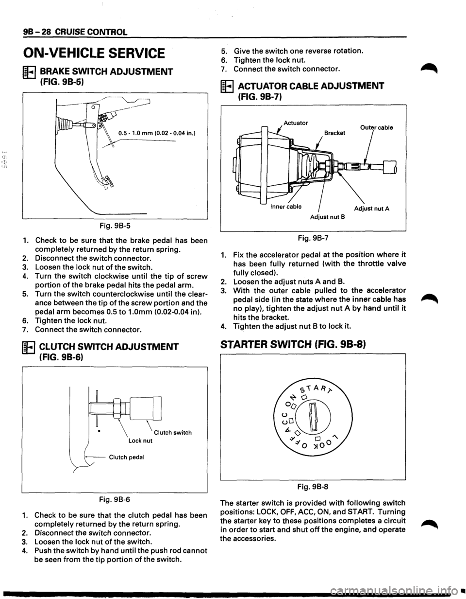
IE BRAKE SWITCH ADJUSTMENT
(FIG. 9B-5)
0.5 -1.0 mm (0.02 -0.04 in.}
Fig. 98-5
1. Check to be sure that the brake pedal has been
completely returned by the return spring.
2. Disconnect the switch connector.
3. Loosen the lock nut of the switch.
4. Turn the switch clockwise until the tip of screw
portion of the brake pedal hits the pedal arm.
5. Turn the switch counterclockwise until the clear
ance between the
tip of the screw portion and the
pedal arm becomes 0.5
to 1.0mm (0.02-0.04 in).
6. Tighten the lock nut.
7. Connect the switch connector.
IE CLUTCH SWITCH ADJUSTMENT
(FIG. 9B-6)
Clutch switch
--Clutch pedal
Fig. 98-6
1. Check to be sure that the clutch pedal has been
completely returned by
the return spring.
2. Disconnect the switch connector.
3. Loosen the lock nut of the switch.
4. Push the switch by hand until the push rod cannot
be seen from the tip portion of the switch.
5. Give the switch one reverse rotation.
6. Tighten the lock nut.
7. Connect the switch connector.
IE ACTUATOR CABLE ADJUSTMENT
(FIG. 9B-7)
Actuator
Adjust nut A
Adjust nut B
Fig. 98-7
1. Fix the accelerator pedal at the position where it
has been fully returned (with the throttle valve
fully closed).
2. Loosen the adjust nuts A and B.
3. With the outer cable pulled to the accelerator
pedal side (in the state
where the inner cable has
no play),
tighten the adjust nut A by hand until it
hits the bracket.
4. Tighten the adjust nut 8 to lock it.
STARTER SWITCH (FIG. 98-8)
Fig. 98-8
The starter switch is provided
with following switch
positions:
LOCK, OFF, ACC, ON, and START. Turning
the starter key to these positions completes a circuit
in
order to start and shut off the engine, and operate
the accessories.
Page 1625 of 1928
Supplemental Restraint System 9J-1
SECTION 9J
SUPPLEMENTAL RESTRAINT SYSTEM
(SRS)
WARNING: THIS VEHICLE IS EQUIPPED WITH A SUPPLEMENTAL INFLATABLE RESTRAINT SYSTEM (SRS).
REFER TO WARNING IN THIS SECTION UNDER "ON-VEHICLE SERVICE" AND THE SRS COMPONENT AND
WIRING LOCATION VIEW IN THIS SECTION BEFORE PERFORMING SERVICE ON OR AROUND SRS
COMPONENTS OR WIRING. FAILURE TO FOLLOW WARNING COULD RESULT IN POSSIBLE AIR BAG
DEPLOYMENT, PERSONAL INJURY, OR OTHERWISE UNNEEDED SRS REPAIRS.
TABLE OF CONTENTS
SUPPLEMENTAL RESTRAINT SYSTEM
(SRS)
SECTION 1 -INTRODUCTION
CAUTION: WHEN FASTENERS ARE REMOVED, ALWAYS REINSTALL THEM AT THE SAME LOCATION
FROM WHICH THEY WERE REMOVED. IF A FASTENER NEEDS TO BE REPLACED, USE THE CORRECT PART
NUMBER FASTENER FOR THAT APPLICATION. IF THE CORRECT PART NUMBER FASTENER IS NOT
AVAILABLE, A FASTENER OF EQUAL SIZE AND STRENGTH (OR STRONGER) MAY BE USED. FASTENERS
THAT ARE NOT REUSED, AND THOSE REQUIRING THREAD LOCKING COMPOUND WILL BE CALLED OUT.
THE CORRECT TORQUE VALUE MUST BE USED WHEN INSTALLING FASTENERS THAT REQUIRE IT. IF THE
ABOVE CONDITIONS ARE NOT FOLLOWED, PARTS OR SYSTEM DAMAGE COULD RESULT.
GENERAL DESCRIPTION • • • . • . . . . • . . . . . . . . . • . . . . • . . . . . . . . • . . . . . . . . • . . . . • . • . . 3
Restraint Devices • • • • • • • • • • • • • • • • • • • • • • • • • • .. • • • • • • • • • • • • • • • • • • • • • • • • • • • • • • • • 3
'W' System Description • • • • • • • • • • • • • • • • • • • • • • • • • • • • • • • • • • • • • • • • • • • • • • • • • • • • • • • • • • 4
SRS Component and wiring Location View . . . . . . • . . . . . . . . . . . • . . . . • . . . . . . . . . . • • 5
COMPONENT DESCRIPTION • • . .
. .
• . . • . .
.
• . . • . . . . . . . . . . . . . . . . . • . • . • . . . . • . • • . . 6
DERM ••••••••••••••••••\
••••••••••••••••••\
••••••••••••••••••\
•••••••• ~ • • • • • 6
"AIR BAG"Warnlng Lamp • • • • • • • • • • • • • • • • • • • • • • • • • • • • • • • • • • • • • • • • .. • • • • • • • • • • • • 6
Dual Pole Arming Sensor • • • • • • • • • • • • • • • • • • • • • • • • • • • • • • • • • • • • • • • • • • • • • • • • • • • • • 6
Discriminating Sensors • • • • • • • • • • • • • • • • • • • • • • • • • • • • • • • • • • • • • • • • • • • • • • • • • • • • • • • 6
SRS Coli Assembly • • • • • • • • • • • • • • • • • • • • • • • • • • • • • • • • • • • • • • • • • • • • • • • • • • • • • • • • • • 7
Inflator Modules • • • • • • • • • • • • • • • • • • • • • • • • • • • • • • • • • • • • • • • • • • • • • • • • • • • • • • • • • • • • 7
Steering Column • • • • • • • • • • • • • • • • • • • • • • • • • • • • • • • • • • • • • • • • • • • • • • • • • • • • • • • • • • • • 7
Knee Bolster • • • • • • • • • • • • • • • • • • • • • • • • • • • • • • • • • • • • • • • • • • • • • • • • • • • • • • • • • • • • • • • 7
DEFINITIONS • • . • . . • • • . • • . • • • • • . • . . • • . • . . . . . . . . . . . . . . . . . . . . . . . . . . . • . . . • • • • • • 8
DIAGNOSIS • • • • • • • • • • • • • • • • • • • • • • • • • • • . • • • • • • . • • • • • . . • • . . . . • • • • • . • • • • • • • • • • • 1 0
Diagnostic Trouble Codes • • • • • • • • • • • • • • • • • • • • • • • • • • • • • • • • • • • • • • • • • • • • • • • • • • • • • 1 0
Scan Tool Diagnostic • • • • • • • • • • • • • • • • • • • • • • • • • • • • • • • • • • • • • • • • • • • • • • • • • • • • • • • • 1 0
Use of Special Tools • • • • • • • • • • • • • • • • • • • • • • • • • • • • • • • • • • • • • • • • • • • • • • • • • • • • • • • • • 1 0
SRS CONNECTOR BODY FACE VIEWS . . . . . . . . . . . • . . . . . . . . . . . . . . . . . . . . . • . . . . . 11
REPAIRS AND INSPECTION REQUIRED AFTER AN ACCIDENT . . . . . • . . . . . . . . . . . 12
Accident With Deployment-component Replacement and Inspections • • • • • • • • • • • • • • • • • • 12
Accident With or Without Deployment-Component Inspections • • • • • • • • • • • • • • • • • • • • • • • 12
Sensor Replacement Guideline ••••••••• II • • • • • • • • • • • • • • • • • • • • • • • • • • • • • • • • • • • • • • • 12
Wiring Damage ••••••••••••••••••\
••• II • • • • • • • • • • • • • • • • • • • • • • • • • • • • • • • • • • • • • • • 12
SRS Conector (Plastic Body and Terminal Metal Pin) Damage • • • • • • • • • • • • • • • • • • • • • • • • • 12
Page 1626 of 1928
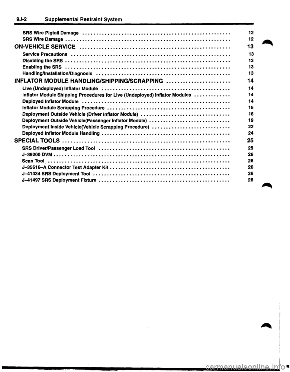
9J-2 Supplemental Restraint System
SRS Wire Pigtail Damage ..........................•..........•...............
SRS Wire Damage ...........................................•...............
ON-VEHICLE SERVICE ......................................•.•..•..........
Service Precautions ••••.••••••••••••••\
••••••••••••••••••\
••••••••••••••••••\
••
Disabling the SRS ...........................................•...............
Enabling the SRS ................................•..........•....•.....•.... \
Handling/Installation/Diagnosis ..........•.••.......•......•...•........•.•.•\
.•
INFLATOR MODULE HANDLING/SHIPPING/SCRAPPING •....•••••..•.....•••..
Live (Undeployed) Inflator Module ••••••••••••••••••\
••••••••••••••••••\
••••••••••
Inflator Module Shipping Procedures for Live (Undeployed) Inflator Modules •••••••••••••
Deployed Inflator Module ••••••••••••••••••\
••••••••••••••••••\
•••••••••••••••••
Inflator Module Scrapping Procedure ••••••••••••••••••\
••••••••••••••••••\
••••••••
Deployment Outside Vehicle (Driver Inflator Module) ••••••••••••••••••\
••••••••••••••
Deployment Outside Vehicle(Passenger Inflator Module) ••••••••••••••••••\
•••••••••••
Deployment Inside Vehicle(Vehlcle Scrapping Procedure) ••••••••••••••••••\
••••••••••
Deployed Inflator Module Handling ••••••••••••••••••\
••••••••••••••••••\
••••••••••
SPECIAL TOOLS ............................................................ .
SRS Driver/Passenger Load Tool .................•.....••.•••••....•••.\
•••.••••
J-39200 DVM . . . . . . . . . . . . . . • . . . . . . . . . . • . . . . . . . . . . . . . . . • • . • . • . . • . • • . . . . . . . • . .
Scan Tool ...............................................•..•..••.•\
••.....•
J-35616-A Connector Test Adapter Kit ••••••••••••••••••\
••••••••••••••••••\
•••••••
J-41434 SRS Deployment Tool ••••••••••••••••••\
••••••••••••••••••\
•••••••••••••
J-41497 SRS Deployment Fixture ••••••••••••••••••\
••••••••••••••••••\
•••••••••••
12
12
~ 13
13
13 13
13
14
14
14
14
15 16
19
22
24
25
25
26
26
26
26
26
~
•