service ISUZU TROOPER 1995 Workshop Manual
[x] Cancel search | Manufacturer: ISUZU, Model Year: 1995, Model line: TROOPER, Model: ISUZU TROOPER 1995Pages: 1928
Page 1636 of 1928
9J-12 Supplemental Restraint System
REPAIRS AND INSPECTIONS REQUIRED AFTER AN
ACCIDENT
NOTE
• If
any SRS components are damaged, they must be
replaced. If SRS component mounting points are
damaged, they must be
replaced.
•
Never use SRS parts from another vehicle. This
does not
include remanufactured parts purchased
from an authorized
dealer; they may be used for SRS
repairs.
• Do not attempt to service discriminating sensors, the
dual pole arming sensor, the DERM, the SRS coil
assembly,
or the inflator modules. Service of these
items is by
replacement only.
•
Verify the part number of replacement inflator
modules.
CAUTION: PROPER OPERATION OF THE
SENSORS AND SUPPLEMENTAL RESTRAINT
SYSTEM (SRS) REQUIRES THAT ANY REPAIRS TO
THE VEHICLE STRUCTURE RETURN IT TO THE
ORIGINAL PRODUCTION CONFIGURATION.
DEPLOYMENT REQUIRES, AT A MINIMUM,
REPLACEMENT OF THE SENSORS, THE INFLATOR
MODULE,
AND DIMENSIONAL INSPECTION OF THE
STEERING COLUMN. ANY VISIBLE DAMAGE TO
THE DERM MOUNTING BRACKET(S) REQUIRES
REPLACEMENT, SENSORS MUST BE REPLACED,
AND THE
STEERING COLUMN MUST BE
DIMENSIONALLY INSPECTED, WHETHER
DEPLOYMENT
OCCURRED OR NOT.
ACCIDENT WITH DEPLOYMENT-COMPONENT
REPLACEMENT AND
INSPECTIONS
Certain SRS components must be replaced for damage
after a
frontal crash involving air bag deployment. Those
components are:
• Inflator modules.
• All
sensors. It is include among the Dual pole Arming
Sensor.
CAUTION
•
Refer to "Sensor Replacement Guidelines"
below for Important Information on sensor
replacement In both deployment and
non-deployment crashes.
• SRS coil assembly, Inspect wiring and connector for
any signs of scorching,
melting, or damage due to
excessive heat.
Replace if damaged. Refer to this in
section
3.
ACCIDENT WITH OR WITHOUT DEPLOYMENT
COMPONENT INSPECTIONS
Certain SRS and restraint system components must be
inspected after any crash, whether the air bag
deployed
or not. Those components are:
• Steering column-Dimensionally inspect per
"Checking Steering Column for Accident Damage" in
section 3.
• Sensors, if in the area of accident damage. If with
deployment, All sensors must be replaced.
CAUTION
•
Refer to "Sensor Replacement Guidelines"
below for Important information on sensor
replacement in both deployment and
non-deployment crashes.
• Knee bolsters and mounting points-Inspect for any
distortion, bending, cracking, or other damage.
• 1/P steering column reinforcement plate-Inspect for
any distortion, bending, cracking, or other damage.
• liP braces-Inspect for any distortion, bending,
cracking, or other damage.
~
• Seat belts and mounting points-Refer to "Seat Belts"
in SECTION 10.
SENSOR REPLACEMENT GUIDELINES
SRS sensor replacement policy requires replacement of
the all sensors, after crash Involving Air Bag
Deployment.
WIRING DAMAGE
If any SRS wire harness is damaged, it should be
replaced. Don't repair SRS HARNESS. It is replace only.
SRS CONNECTOR {PLASTIC BODY AND
TERMINAL METAL PIN) DAMAGE
If any connector or terminal in the SRS wire harness
(except
pigtails) is damaged, it should be replaced.
SRS WIRE PIGTAIL DAMAGE
If the wiring pigtail (a wire or wires attached directly to the
device,
not by a connector)is damaged, the entire
component(with pigtail)must be replaced. Examples of
"pigtail" components are the driver inflator module, the
passenger
inflator module, the discriminating sensors,
the
dual pole arming sensor and the SRS coil assembly. ~
SRS WIRE DAMAGE
If any wire except the pigtail is damaged, the wire should
be replaced.
Ill
Page 1637 of 1928
Supplemental Restraint System 9J-13
ON-VEHICLE SERVICE
SERVICE PRECAUTIONS
WARNING: WHEN PERFORMING SERVICE ON OR
AROUND SRS COMPONENTS OR SRS WIRING,
FOLLOW
THE PROCEDURES LISTED BELOW TO
TEMPORARILY DISABLE THE SRS. FAILURE TO
FOLLOW PROCEDURES COULD RESULT IN
POSSIBLE AIR
BAG DEPLOYMENT, PERSONAL
INJURY OR OTHERWISE
UNNEEDED SRS
REPAIRS.
The DERM in Driver-Passenger SRS can maintain
sufficient voltage to cause a deployment for up to 2
minutes after the ignition switch is turned
"OFF," the
battery is disconnected, or the fuse powering the DERM
is removed.
Many of the service procedures require removal of the
"AIR BAG" fuse, and disconnection of the inflator
modules from the deployment loop to avoid an accidental
deployment.
If the inflator module is disconnected from
the deployment loop as noted in the "Disabling the
SRS"
procedure that follows, service can begin immediately
without waiting for the 2-minute time period to expire.
DISABLING THE SRS
REMOVAL
Turn the ignition switch to "OFF"
1. Remove SRS fuse C-21, C-22, C-23 and C-24 from
left dash side lower fuse block.
2. Disconnect yellow 3-way connector at the base of
steering column.
3. Remove 1/P compartment door assembly, Refer to
"Passenger inflator module replacement" in section
9J-132.
4. Disconnect yellow 4-way connector behind the 1/P
compartment door assembly.
IMPORTANT
• With the "AIR BAG" fuse removed and ignition switch
"ON," if Fuse 21 left. the "AIR BAG" warning lamp will
be "ON." This is normal operation and does not
indicate an
SRS malfunction.
ENABLING THE SRS
INSTALLATION
Turn ignition switch to "LOCK" and remove key.
1. Connect yellow 4-way connector for passenger
inflator module.
2. 1/P compartment door assembly, Refer to
"Passenger inflator module replacemenf' in section
9J-3.
3. Connect yellow 2-way connector at the base of the
steering column.
4. Install "AIR BAG" fuse C-21, C-22, C-23 and C-24 to
left dash side lower fuse block.
Turn ignition switch to
"RUN" and verify that the "AIR
BAG"
warning lamp flashes seven times and then turns
"OFP' If it does not operate as described, perform the
"SRS Diagnostic System Check" in section 9J-2.
HANDLING/INSTALLATION/DIAGNOSIS
1. Inflator modules should not be subjected to
temperatures above
65°C{150°F).
2. Discriminating sensors, inflator modules, arming
sensors, or DERMs should not be used if they have
been dropped from a height
of 91.4 centimeters
{3feet).
3. When a discriminating sensor or arming sensor is
replaced, it must be oriented with the arrow on the
sensor pointing toward the front of the vehicle.
It is
very important for the discriminating sensors and
arming sensor to be located flat on the mounting
surface, parallel to the vehicle datum line.
It is
important that the sensor mounting surface is free of
any dirt or other foreign material.
4. Do not apply power to the SRS unless all
components are connected or a diagnostic chart
requests it, as this
will set a diagnostic trouble code.
5. The "SRS Diagnostic System Check" must be the
starting point of any
SRS diagnostics. The "SRS
Diagnostic System Check" will verify proper "AIR
BAG"
warning lamp operation and will lead you to the
correct chart to diagnose any
SRS malfunctions.
Bypassing these procedures may result
in extended
diagnostic time, incorrect diagnosis, and incorrect
parts replacements.
Page 1638 of 1928
--
9J-14 Supplemental Restraint System
INFLATOR MODULE HANDLING/SHIPPING/SCRAPPI G
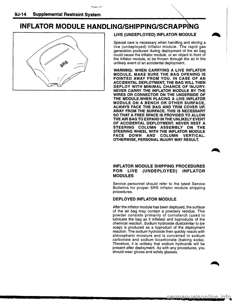
LIVE (UNDEPLOYED) INFLATOR MODULE ~
Special care is necessary when handling and storing a
live (undeployed) inflator module. The rapid gas
generation produced during deployment of the air bag
could cause the inflator module, or an object in front of
the inflator module,
to be thrown through the air in the
unlikely event of an accidental deployment.
WARNING: WHEN CARRYING A LIVE INFLATOR
MODULE, MAKE SURE THE BAG OPENING IS
POINTED
AWAY FROM YOU. IN CASE OF AN
ACCIDENTAL DEPLOYMENT, THE BAG WILL THEN
DEPLOY WITH MINIMAL CHANCE OF INJURY.
NEVER CARRY THE INFLATOR MODULE BY THE
WIRES OR CONNECTOR ON THE UNDERSIDE OF
THE MODULE.WHEN PLACING A LIVE INFLATOR
MODULE ON A BENCH OR OTHER SURFACE,
ALWAYS FACE THE BAG AND TRIM COVER UP,
AWAY FROM THE SURFACE. THIS IS NECESSARY
SO
THAT A FREE SPACE IS PROVIDED TO ALLOW
THE AIR BAG TO EXPAND IN THE UNLIKELY EVENT
OF ACCIDENTAL DEPLOYMENT. NEVER REST A
STEERING COLUMN ASSEMBLY ON THE
STEERING WHEEL WITH THE INFLATOR MODULE
FACE
DOWN AND COLUMN VERTICAL.
OTHERWISE, PERSONAL INJURY MAY RESULT.
INFLATOR MODULE SHIPPING PROCEDURES
FOR
LIVE (UNDEPLOYED) INFLATOR
MODULES
Service personnel should refer to the latest Service
Bulletins for proper SRS inflator module shipping
procedures.
DEPLOYED INFLATOR MODULE
After the inflator module has been deployed, the surface
of the air bag may contain a powdery residue. This
powder consists primarily of cornstarch (used to
lubricate the bag as it inflates) and byproducts of the
chemical reaction. Sodium hydroxide dust( similar
to lye
soap)
is produced as a byproduct of the deployment
reaction. The sodium hydroxide then quickly reacts with
atmospheric moisture and is converted to sodium
carbonate and sodium bicarbonate (baking soda).
Therefore, it
is unlikely that sodium hydroxide will be
present after deployment. As with any procedures, you
should wear gloves and safety glasses.
Page 1640 of 1928
9J-16 Supplemental Restraint ~
DEPLOYMENT OUTSIDE VEHICLE (DRIVER
INFLATOR
MODULE)
Deployment outside the vehicle is proper when the
vehicle is to be returned to service. This includes, for
example, situations in which the vehicle will be returned
to
useful service after a functionally or cosmetically
deficient
inflator module is replaced. Deployment and
disposal of a malfunctioning inflator module is, of course,
subject to any required retention period.
For deployment of a
live (undeployed) inflator module
outside the vehicle, the deployment procedure must be
followed exactly. Always wear safety glasses during this
deployment procedure
until a deployed inflator module is
scrapped
or until an undeployed inflator module is
shipped. Before performing the procedures, you
should
be familiar with servicing the SRS and with proper
handling of the inflator module. Procedures should be
read fully before they are performed.
The following procedure requires use of J-41434
SRS
deployment harness with appropriate pigtail adapter. Do
not attempt procedure without J-41434 adapter.
WARNING: FAILURE TO FOLLOW PROCEDURES
IN
THE ORDER LISTED MAY RESULT IN PERSONAL
INJURY.
NEVER CONNECT DEPLOYMENT
HARNESS TO ANY POWER SOURCE BEFORE
CONNECTING DEPLOYMENT HARNESS TO THE
DRIVER INFLATOR MODULE. DEPLOYMENT
HARNESS SHALL REMAIN SHORTED AND NOT BE ~
CONNECTED TO A POWER SOURCE UNTIL THE
AIR BAG IS TO BE DEPLOYED. THE INFLATOR
MODULE WILL IMMEDIATELY DEPLOY THE AIR
BAG WHEN A POWER SOURCE IS CONNECTED TO
IT. WEAR SAFETY GLASSES THROUGHOUT THIS
ENTIRE DEPLOYMENT AND DISPOSAL
PROCEDURE.
NOTE
• This information applies only to driver inflator
modules. Refer to "Deployment Outside
Vehicle(Passenger Inflator Module)" in this section
for information on passenger inflator module
scrapping.
1. Turn ignition switch to "LOCK," remove key and put
on safety glasses.
2. Inspect J-41434 SRS Deployment Harness and
appropriate
pigtail adapter for damage. If harness or
pigtail adapter is damaged, discard and obtain a
replacement.
•
Page 1643 of 1928
~ Supplemental Restraint System 9J-19
26. Temporarily store the driver inflator module with its inflator module can be found in the applicable service
vinyl trim cover facing
up, away from the surface manual or in a service bulletin.
upon which is rests.
27.
Call the Technical Assistance group for further
assistance.
DEPLOYMENT OUTSIDE VEHICLE
(PASSENGER INFLATOR MODULE)
WARNING: FAILURE TO FOLLOW PROPER SRS
INFLATOR MODULE DISPOSAL PROCEDURES
CAN RESULT IN AIR BAG DEPLOYMENT WHICH
MAY CAUSE PERSONAL INJURY. UNDEPLOYED
INFLATOR MODULES MUST NOT BE DISPOSED OF
THROUGH NORMAL REFUSE CHANNELS. THE
UNDEPLOYED INFLATOR MODULE CONTAINS
SUBSTANCES
THAT CAN CAUSE SEVERE ILLNESS
OR
PERSONAL INJURY IF THE SEALED
CONTAINER IS DAMAGED DURING DISPOSAL.
DISPOSAL
IN ANY MANNER INCONSISTENT WITH
PROPER PROCEDURES MAY BE A VIOLATION OF
FEDERAL, STATE AND/OR LOCALLAWS.
Deployment out of the vehicle is proper when the vehicle
is to be returned to service. This includes, for example,
situations
in which a functionally or cosmetically deficient
inflator module
is replaced. Deployment and disposal of
an inflator module is, of course, subject to any required
reterntion period.
For deployment
of a live inflator module out of the
·'-" vehicle, the deployment procedure must be followed
exactly.
ALWAYS wear safety glasses during this
deployment procedure until the deployed inflator module
is scrapped. Before performing the procedures you
should
be familiar with servicing the SRS system and
with proper handling of the inflator module. Procedures
should be read fully before they are performed.
The following procedure requires use of J-41434
SIR
Deployment Harness with the appropriate pigtail
adapter. The procedure also requires the use of J-41497
Passenger
Side SRS Module Deployment Fixture. Do
not attempt this procedure without J-41434 and adapter,
and J-41497.
WARNING: FAILURE TO FOLLOW PROCEDURES
IN THE ORDER LISTED MAY RESULT IN PERSONAL
INJURY.
NEVER CONNECT DEPLOYMENT
HARNESS TO ANY POWER SOURCE BEFORE
CONNECTING DEPLOYMENT HARNESS TO THE
INFLATOR MODULE. DEPLOYMENT HARNESS
SHALL REMAIN SHORTED AND NOT BE
CONNECTED TO A POWER SOURCE UNTIL THE
AIRBAG IS TO BE DEPLOYED. THE INFLATOR
MODULE WILL IMMEDIATELY DEPLOY THE
AIRBAG WHEN A POWER SOURCE IS CONNECTED
TO IT. WEAR SAFETY GLASSES THROUGHOUT
THIS ENTIRE DEPLOYMENT AND DISPOSAL
~ PROCEDURE.
NOTE: This information applies only to passenger
inflator modules. Information for disposing of a live driver
1. Turn ignition switch to "LOCK", remove key, and put
on safety glasses.
2. Inspect J-41434 SRS Deployment Harness and
appropriate pigtail adapter for damage.
If harness or
pigtail is damaged, discard and obtain a
replacement.
Page 1644 of 1928
9J-20 Supplemental Restraint SysteA
~----------------------------------~
--
=======C.pp=::::J
============~~ 'r;;;;r=
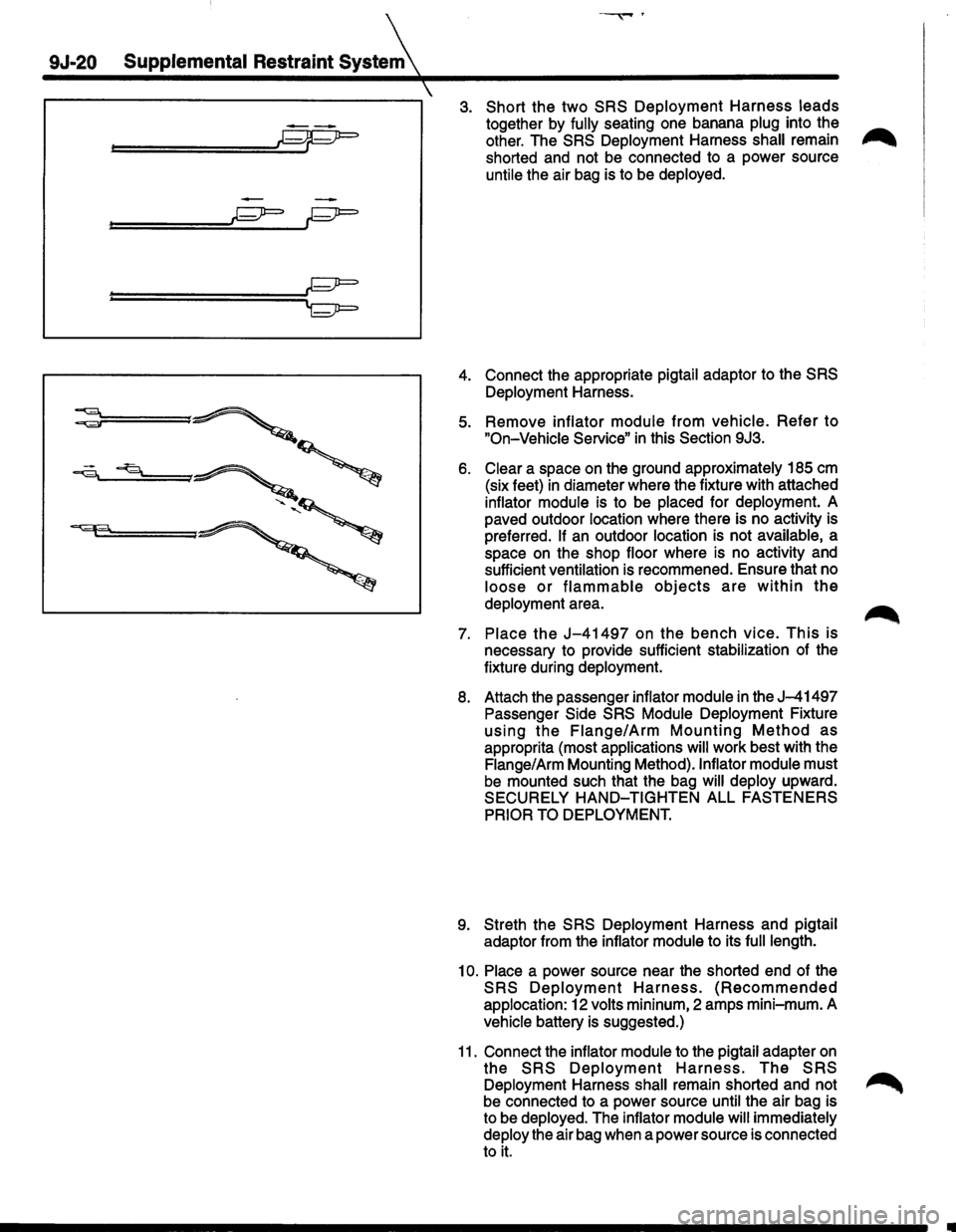
3. Short the two SRS Deployment Harness leads
together by fully seating one banana plug into the ..-.,.
other. The SRS Deployment Harness shall remain ,..,......
shorted and not be connected to a power source
untile the air bag is to be deployed.
4. Connect the appropriate pigtail adaptor to the SRS
Deployment Harness.
5. Remove inflator module from vehicle. Refer to
"On-Vehicle Service" in this Section 9J3.
6. Clear a space on the ground approximately 185 em
(six feet) in diameter where the fixture with attached
inflator module is to be placed for deployment. A
paved outdoor location where there is no activity is
preferred.
If an outdoor location is not available, a
space on the shop floor where is no activity and
sufficient ventilation is recommened. Ensure that no
loose or flammable objects are within the
deployment area.
7. Place the J-41497 on the bench vice. This is
necessary to provide sufficient stabilization of the
fixture during deployment.
8. Attach the passenger inflator module in the J-41497
Passenger Side SRS Module Deployment Fixture
using the Flange/Arm Mounting Method as
approprita (most applications will work best with the
Flange/Arm Mounting Method).lnflator module must
be mounted such that the bag will deploy upward.
SECURELY
HAND-TIGHTEN ALL FASTENERS
PRIOR TO DEPLOYMENT.
9. Streth the SRS Deployment Harness and pigtail
adaptor from the inflator module to its
full length.
10. Place a power source near the shorted end of the
SRS Deployment Harness. (Recommended
applocation: 12 volts mininum, 2 amps mini-mum. A
vehicle battery is suggested.)
11. Connect the inflator module to the pigtail adapter on
the SRS Deployment Harness. The SRS
Deployment Harness shall remain shorted and not ~
be connected to a power source until the air bag is
to be deployed. The inflator module
will immediately
deploy the air bag when a power source is connected
to it.
Page 1648 of 1928
9J-24 Supplemental Restraint System
hy~roxide th~n quickly reacts with atmospheriC' PROCEDURES COULD RESULT IN PERSONAL
mo1sture and IS converted to sodium carbonate and INJURY.
so~ium bicarbonate (baking soda). Therefore, it is
unlikely that sodium hydroxide will be present after
deployment.
As a precaution, however, gloves and
safety glasses are recommended to prevent any
possible irritation of the skin or eyes.
WARNING: SAFETY PRECAUTIONS MUST BE
OBSERVED WHEN HANDLING A DEPLOYED
INFLATOR MODULE. AFTER DEPLOYMENT, THE
METAL
SURFACES OF THE INFLATOR MODULE
WILL BE VERY HOT. ALLOW THE INFLATOR
MODULE TO COOL BEFORE HANDLING ANY
METAL PORTION OF IT. DO NOT PLACE THE HOT
DEPLOYED INFLATOR MODULE NEAR ANY
FLAMMABLE OBJECTS. FAILURE TO FOLLOW
PROCEDURES COULD RESULT IN FIRE OR
PERSONAL INJURY.
After an inflator module has been deployed, the metal
canister and surrounding areas of the inflator module will
be very hot. Do not touch the metal areas of the inflator
module for about
10 minutes after deployment. If the
deployed inflator module must be moved before it
is cool,
wear gloves
and handle by the air bag or vinyl trim.
31. S~o~t the driver deployment harness wires by
tw1st1ng together one end from each. Repeat this
procedure for the passenger deployment harness.
32. Carefully remove drop cloth from vehicle and clean
off any fragments or discard drop cloth entirely.
33. Disconnect driver deployment harness and
passenger deployment harness from vehicle and
discard.
34.
In the unlikely event that either or both of the inflator
modules did not deploy after following these
procedures, proceed immediately with Steps 36
through
38. If the inflator module deployed proceed
step
35.
35. With both air bags deployed, the vehicle may be
scrapped in the same manner as a non-SRS
equipped vehicle.
NOTE: The remaining steps are to be followed in the
unlikely event that the inflator module did not deploy otter
following these procedures.
36. Remove the undeployed inflator module(s) from the
vehicle. For driver inflator module refer to
in this
section for passenger inflator module
"On-Vehicle
Service".
WARNING:
WHEN STORING A LIVE INFLATOR
MODULE OR WHEN LEAVING A LIVE INFLATOR
MODULE
UNATTENDED ON A BENCH OR OTHER
SURFACE, ALWAYS FACE THE BAG AND TRIM
COVER
UP, AWAY FROM THE SURFACE. THIS IS
NECESSARY SO THAT A FREE SPACE IS
PROVIDED
TO ALLOW THE AIR BAG TO EXPAND IN
THE UNLIKELY EVENT OF ACCIDENTAL
DEPLOYMENT. FAILURE TO FOLLOW
37. Temporarily store the inflator module with the air bag
opening facing
up, away from the surface upon which
it rests.
38. Call the Technical Assistance group for further
assistance.
DEPLOYED INFLATOR MODULE HANDLING
After the inflator module has been deployed, the surface
of the air bag may contain a powdery residue. This
powder
consists primarily of cornstarch (used to
lubricate the bag as it inflates) and byproducts of the
chemical reaction.
Sodium hydroxide dust (similar to lye
soap)
is produced as a byproduct of the deployment
reaction. The sodium hydroxide then quickly reacts with
atmospheric moisture and is converted
to sodium
carbonate and sodium bicarbonate (baking soda}.
Therefore, it
is unlikely that sodium hydroxide will be
present after deployment. As with many service
procedures, you should wear gloves and safety glasses.
Page 1654 of 1928
9J-30 Supplemental Restraint System (SRS)
HOW TO USE THIS SECTION
DIAGNOSTIC PROCEDURES
WARNING: TO AVOID DEPLOYMENT WHEN
TROUBLESHOOTING THE SRS, DO NOT USE
ELECTRICAL TEST EQUIPMENT SUCH AS A
BATTERY-POWERED OR AC-POWERED
VOLTMETER, OHMMETR,ETC. ,OR ANY TYPE OF
ELECTRICAL EQUIPMENT OTHER THAN THAT
SPECIFIED IN THIS MANUAL. DO NOT USE A
NON-POWERED PROBE TYPE TESTER.
INSTRUCTIONS IN THIS MANUAL MUST BE
FOLLOWED CAREFULLY, OTHERWISE PERSONAL
INJURY
MAY RESULT.
The diagnostic procedures used in this section are
designed to aid
in finding and repairing SRS problems.
Outlined below
are the steps to find and repair SRS
problems quickly
and effectively. Failure to carefully
follow these procedures may result in extended
diagnostic time, incorrect diagnosis and incorrect parts
replacement.
1. Perform the "SRS Diagnostic System Check". The
"SRS Diagnostic System Check" should always be
the starting point of any SRS diagnostics. The "SRS
Diagnostic System Check" checks for proper "AIR
BAG" indicator operation and checks for SRS trouble
codes using both "Flash Code" and "Scan Tool"
Methods.
2. Refer to the proper diagnostic chart as directed by
the
"SRS Diagnostic System Check". The "SRS
Diagnostic System Check" will lead you to the correct
chart to diagnose any
SRS problems. Bypassing
these procedures may
result in extended diagnostic
time, incorrect diagnosis and incorrect parts
replacement.
3. Repeat the "SRS Diagnostic System Check" after
any repair
or diagnostic procedures have been
performed.Performing the
"SRS Diagnostic System
Check" after all repair or diagnostic procedures will
assure that the repair has been made correctly and
that no other conditions exist.
DIAGNOSTIC CODES
The Diagnostic Energy Reserve Module (DERM)
maintains a history record of all diagnostic codes that
have been detected since the
SRS codes were last
cleared
during service.
1. Current Codes -Faults that are presently detected
this ignition
cycle. Active and Cycle codes are stored
in RAM (Random Access Memory).
2. History
Codes-All faults detected since the last time
the history
fault memory was cleared. History codes
are stored in EEPROM (Electrically Erasable
Programmable Read Only Memory )
HOW TO READ TROUBLE CODES
All codes (Active cycle and history) can be read (or
cleared) by using a Scan Tool (Portable Diagnostic Tool
[PDT)) or equivalent. If a PDT is not available, have the
vehicle serviced by a Saturn Dealer.
HOW TO CLEAR TROUBLE CODES
Trouble codes can only be cleared by using a Scan Tool.
If
a "Scan Tool" is not available, then inform the owner of
the stored codes and suggest that the codes are
cleared
upon the next visit to a ISUZU dealership.
SCAN TOOL DIAGNOSTICS
A Scan Tool can be used to read current and history
codes and to
clear all history codes after a repair is
complete. The scan tool must be updated to
communicate with the
SRS through a replaceable
cartridge or a manufacturer's update before it can be
used for
SRS diagnostics. To use the scan tool, connect
it to the ALDL connector and turn the ignition switch
"ON". Then follow the manufacturer's directions for
communication with the
SRS. The scan tool reads serial
data from the DERM "Serial Data" output (terminal A 11)
to the ALDL connector (terminal M) Via ISUZU
Convertible Connector (terminal 2).
BASIC KNOWLEDGE REQUIRED
Before using this section of the Service Manual, there is
some basic
knowledge which will be required. Without
this knowledge, you
will have trouble using the diagnostic
procedures
in this section. Use care to prevent harm or
unwanted
deployment. Read all cautions in the service
manual and on warning labels attached to SRS
components.
BASIC ELECTRICAL CIRCUITS
You should understand the basic theory of electricity
including series and parallel circuits, and understand the
voltage drops across series resistors. You should know
the meaning of
voltage (volts), current (amps), and
resistance (ohms). You should understand what
happens in a circuit with an open or a shorted wire. You
should be able to read and understand a wiring diagram.
"FLASH CODE" DIAGNOSTICS
"Flash Code" diagnostics are not implemented for SRS
diagnostic on TROOPER(UX)Vehicles.
Page 1663 of 1928
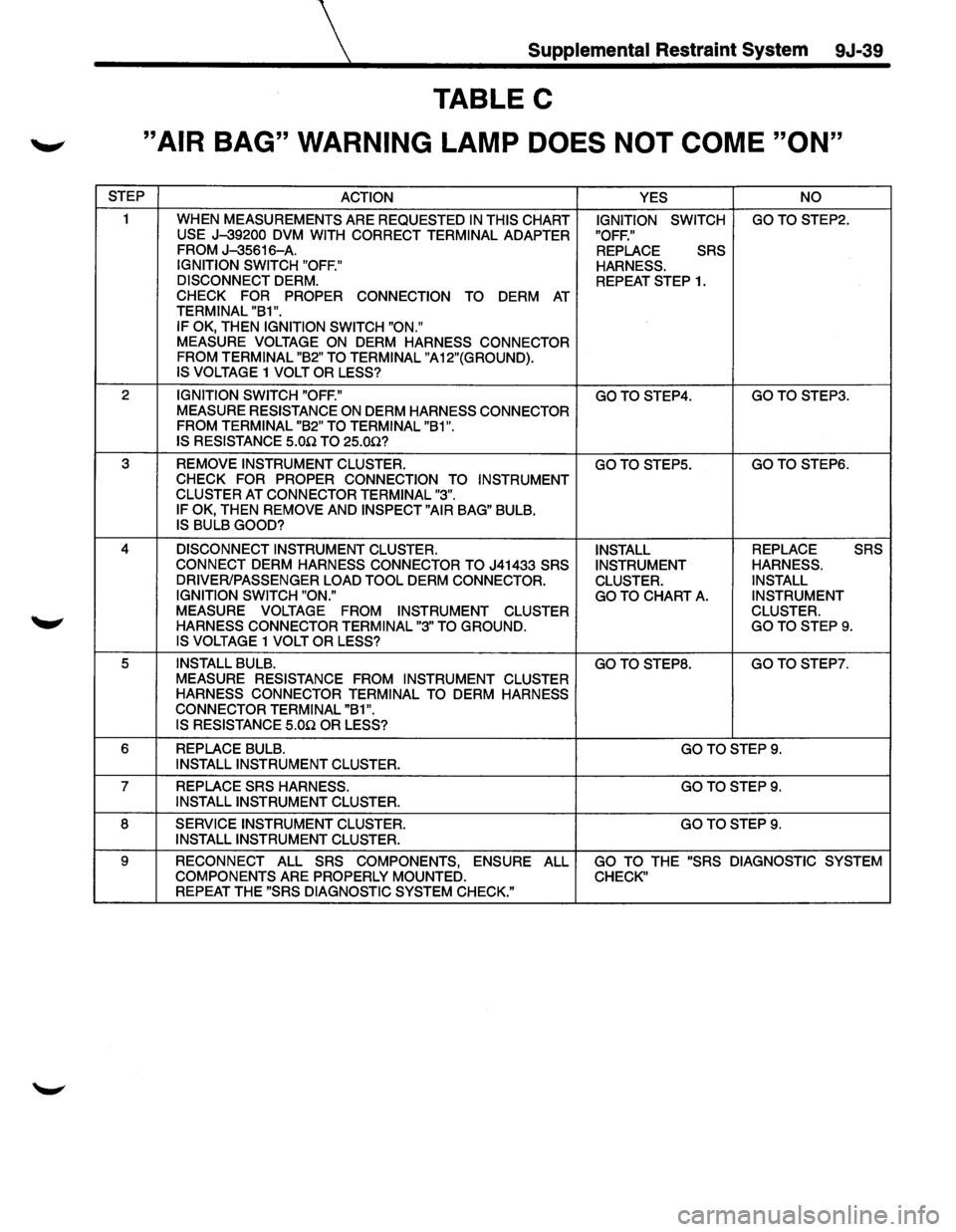
Supplemental Restraint System 9J-39
TABLE C
._, "AIR BAG" WARNING LAMP DOES NOT COME "ON"
STEP
ACTION YES NO
1
WHEN MEASUREMENTS ARE REQUESTED IN THIS CHART IGNITION SWITCH GOTOSTEP2. USE J-39200 DVM
WITH CORRECT TERMINAL ADAPTER "OFF."
FROM J-35616-A. REPLACE SRS
IGNITION SWITCH "OFF."
HARNESS.
DISCONNECT
DERM. REPEAT STEP 1. CHECK FOR PROPER CONNECTION TO DERM AT TERMINAL "B1 ".
IF OK, THEN IGNITION SWITCH "ON." MEASURE VOLTAGE ON DERM HARNESS CONNECTOR
FROM TERMINAL "B2" TO TERMINAL "A12"(GROUND).
IS VOLTAGE
1 VOLT OR LESS?
2 IGNITION SWITCH "OFF." GOTOSTEP4. GOTO STEP3.
MEASURE RESISTANCE ON DERM HARNESS CONNECTOR
FROM TERMINAL "B2" TO TERMINAL "B1".
IS RESISTANCE
5.0.Q TO 25.0.Q?
3 REMOVE INSTRUMENT CLUSTER. GOTOSTEP5. GOTOSTEP6. CHECK FOR PROPER CONNECTION TO
INSTRUMENT
CLUSTER AT CONNECTOR TERMINAL "3".
IF OK, THEN REMOVE AND INSPECT "AIR BAG" BULB. IS BULB GOOD?
4 DISCONNECT INSTRUMENT CLUSTER.
INSTALL REPLACE SRS
CONNECT DERM HARNESS CONNECTOR TO J41433 SRS
INSTRUMENT HARNESS.
DRIVER/PASSENGER LOAD TOOL
DERM CONNECTOR.
CLUSTER. INSTALL
IGNITION SWITCH "ON."
GO TO
CHART A. INSTRUMENT
MEASURE VOLTAGE FROM INSTRUMENT
CLUSTER CLUSTER.
HARNESS CONNECTOR TERMINAL "3" TO
GROUND. GOTOSTEP9. IS VOLTAGE 1 VOLT OR LESS?
5 INSTALL BULB. GOTO STEPS. GO
TO STEP?.
MEASURE RESISTANCE FROM INSTRUMENT CLUSTER
HARNESS CONNECTOR TERMINAL TO
DERM HARNESS
CONNECTOR TERMINAL "B1".
IS RESISTANCE 5.0n OR LESS?
6 REPLACE BULB. GOTOSTEP9. INSTALL INSTRUMENT CLUSTER.
7 REPLACE SRS HARNESS. GOTOSTEP9. INSTALL INSTRUMENT CLUSTER.
8 SERVICE INSTRUMENT CLUSTER. GOTOSTEP9. INSTALL INSTRUMENT CLUSTER.
9
RECONNECT ALL SRS COMPONENTS, ENSURE ALL GO TO THE "SRS DIAGNOSTIC SYSTEM
COMPONENTS ARE PROPERLY MOUNTED. CHECK" REPEAT THE "SRS DIAGNOSTIC SYSTEM CHECK."
Page 1739 of 1928
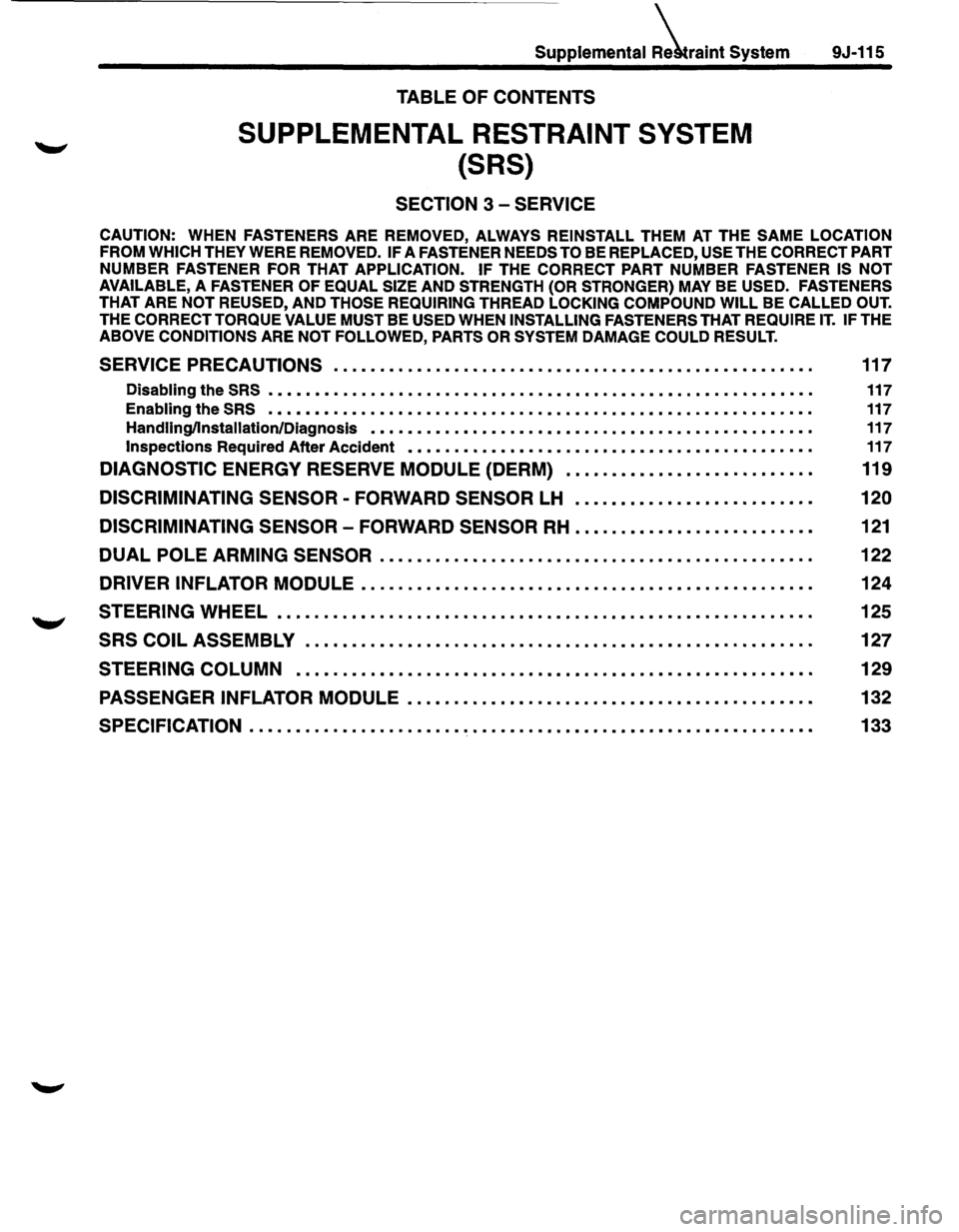
Supplemental iraint System
TABLE OF CONTENTS
SUPPLEMENTAL RESTRAINT SYSTEM
{SRS)
SECTION 3 -SERVICE
9J-115
CAUTION: WHEN FASTENERS ARE REMOVED, ALWAYS REINSTALL THEM AT THE SAME LOCATION
FROM WHICH
THEY WERE REMOVED. IF A FASTENER NEEDS TO BE REPLACED, USE THE CORRECT PART
NUMBER FASTENER
FOR THAT APPLICATION. IF THE CORRECT PART NUMBER FASTENER IS NOT
AVAILABLE,
A FASTENER OF EQUAL SIZE AND STRENGTH (OR STRONGER) MAY BE USED. FASTENERS
THAT ARE NOT REUSED, AND THOSE REQUIRING THREAD LOCKING COMPOUND WILL BE CALLED OUT.
THE CORRECT TORQUE VALUE MUST BE USED WHEN INSTALLING FASTENERS THAT REQUIRE IT. IF THE
ABOVE CONDITIONS ARE NOT FOLLOWED, PARTS OR SYSTEM DAMAGE COULD RESULT.
SERVICE PRECAUTIONS . . . . . . . . . • . . . . . • • . . . . . . . . • . • • . . . . . . . . . . . • . . • • . . . . . . . 117
Disabling the SRS . . . . . . . . . . . . . . . . . . . . . . . . . . . . . . . . . . . . . . . . . . . . . . . . . . . . . . . . . . . 117
Enabling the SRS • • • • • • • • • • • • • • • • • • • • • • • • • • • • • • • • • • • • • • • • • • • • • • • • • • • • • • • • • • • 117
Handling/Installation/Diagnosis • • • • • • • • • • • • • • • • • • • • • • • • • • • • • • • • • • • • • • • • • • • • • • • • 117
Inspections Required After Accident • • • • • • • • • • • • • • • • • • • • • • • • • • • • • • • • • • • • • • • • • • • • 117
DIAGNOSTIC ENERGY RESERVE MODULE (DERM) • • . • • . • • • • . . • . . . • • . . . . • . . . • 119
DISCRIMINATING SENSOR-FORWARD SENSOR LH . • . . • • . • . . • . . • . • . . . • • . . • • . 120
DISCRIMINATING SENSOR
-FORWARD SENSOR RH • . • . . . • • • . • . . . . • • . • . . . . . • • 121
DUAL POLE ARMING SENSOR . . . . . . . . . . • . . . . . • . . . . . . . . . . . . • • . . . . . . . . • . . . . . . . 122
DRIVER INFLATOR MODULE ............•..•........•....•....•....•.........
STEERING WHEEL •........•........•.•......••........•..••..•\
•....•....•..
SRS COIL ASSEMBLY ....•......•.•......•.............•••..•....•\
.....•..••
124
125
127
STEERING COLUMN . . . . . . . . . . . . . . . . . . . . . . . . . . . . . . . . . . . . . . . . . . . . . . . . . . . . . . . . 129
PASSENGER INFLATOR MODULE . . . • . . . . . • . • • . . . . . . . . • . . . • • . . • • . . • • . . . . • • . . • 132
SPECIFICATION . .
. . . . . . . . . . . . . .
• . .
. . . . . .
• . .
. . . .
• • • • • • . . • • . • • • . .
.
• . .
. .
• • . .
.
• • 133