ISUZU TROOPER 1995 Workshop Manual
Manufacturer: ISUZU, Model Year: 1995, Model line: TROOPER, Model: ISUZU TROOPER 1995Pages: 1928
Page 181 of 1928
[L!) INSPECTION AND REPAIR
Make necessary parts replacement if wear, damage,
corrosion
or any other abnormal conditions are found
through inspection.
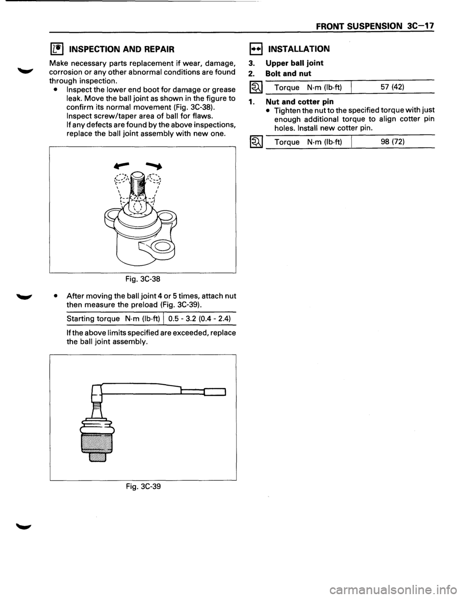
• Inspect the lower end boot for damage or grease
leak. Move the ball joint as shown in the figure to
confirm its normal movement (Fig. 3C-38).
Inspect screw/taper area of ball for flaws.
If
any defects are found by the above inspections,
replace the ball joint assembly with new one.
Fig. 3C-38
• After moving the ball joint 4 or 5 times, attach nut
then measure the preload (Fig. 3C-39).
Starting torque
N·m (lb·ft) I 0.5 -3.2 (0.4 - 2.4)
lfthe above limits specified are exceeded, replace
the ball joint assembly.
Fig. 3C-39
FRONT SUSPENSION 3C-17
1••1 INSTALLATION
3. Upper ball joint
2. Bolt and nut
~~~--T~o_rq~u_e __ N_·m~(l_b_·ft~)_L _____ 5_7_(4_2_) ____ _
1. Nut and cotter pin
• Tighten the nut to the specified torque with just
enough
additional torque to align cotter pin
holes. Install new cotter pin.
1-"i"' I Torque N·m (lb·ft) j 98 (72) ~---~--~~--------
Page 182 of 1928
3C-18 FRONT SUSPENSION
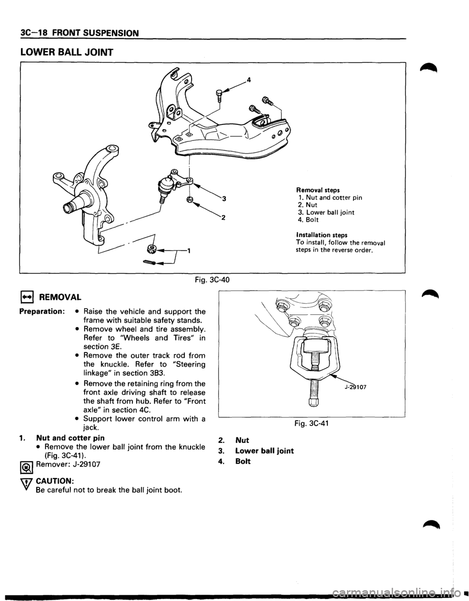
LOWER BALL JOINT
Fig. 3C-40
1••1 REMOVAL
Preparation: • Raise the vehicle and support the
frame
with suitable safety stands.
• Remove wheel and tire assembly.
Refer to "Wheels and Tires" in
section
3E.
• Remove the outer track rod from
the knuckle. Refer to "Steering
linkage"
in section 383.
• Remove the retaining ring from the
front axle driving shaft to release
the shaft from hub. Refer to "Front
axle"
in section 4C.
• Support lower control arm with a
jack.
1. Nut and cotter pin
• Remove the lower ball joint from the knuckle
(Fig. 3C-41).
1®..1 Remover: J-291 07
\f7 CAUTION:
VI Be careful not to break the ball joint boot.
2. Nut
3. Lower ball joint
4. Bolt
Removal steps 1. Nut and cotter pin
2. Nut
3. Lower
ball joint 4. Bolt
Installation
steps
To
install, follow the removal steps in the reverse order.
Fig. 3C-41
..
Page 183 of 1928
I L•IINSPECTION AND REPAIR
Make necessary parts replacement if wear, damage,
corrosion
or any other abnormal condition are found
through inspection.
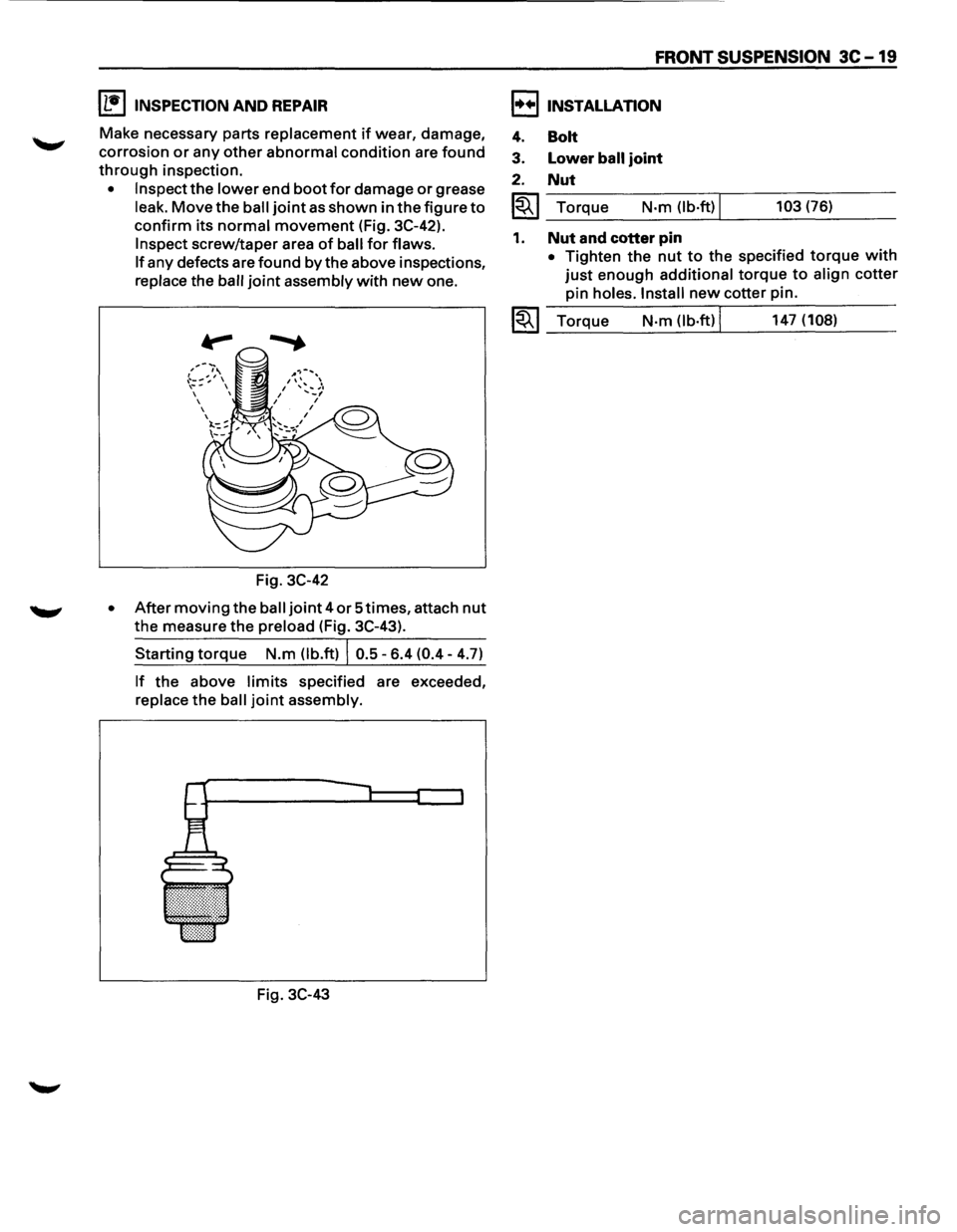
• Inspect the lower end boot for damage or grease
leak.
Move the ball joint as shown in the figure to
confirm its normal movement (Fig. 3C-42).
Inspect screw/taper area of ball for flaws.
If
any defects are found by the above inspections,
replace the ball
joint assembly with new one.
,--~:_,.--,',\ ,-...
~ .. :::: , \~-,
Fig. 3C-42
• After moving the ball joint 4 or Stimes, attach nut
the measure the preload (Fig. 3C-43).
Starting torque N.m (lb.ft) I 0.5-6.4 (0.4-4.7)
If the above limits specified are exceeded,
replace
the ball joint assembly.
Fig.
3C-43
FRONT SUSPENSION 3C-19
I••! INSTALLATION
4.
3.
2.
Bolt
Lower ball joint
Nut
I~I_To_r_:_q_ue __ N_·m_O_b_·ft_) Ll ___ 10_3_(7_6_) __ _
1. Nut and cotter pin
• Tighten the nut to the specified torque with
just enough additional torque to align cotter
pin
holes. Install new cotter pin.
~~~ Torque N·m (lb·ft) I 147 (108) --~----~-----------
Page 184 of 1928
3C-20 FRONT SUSPENSION
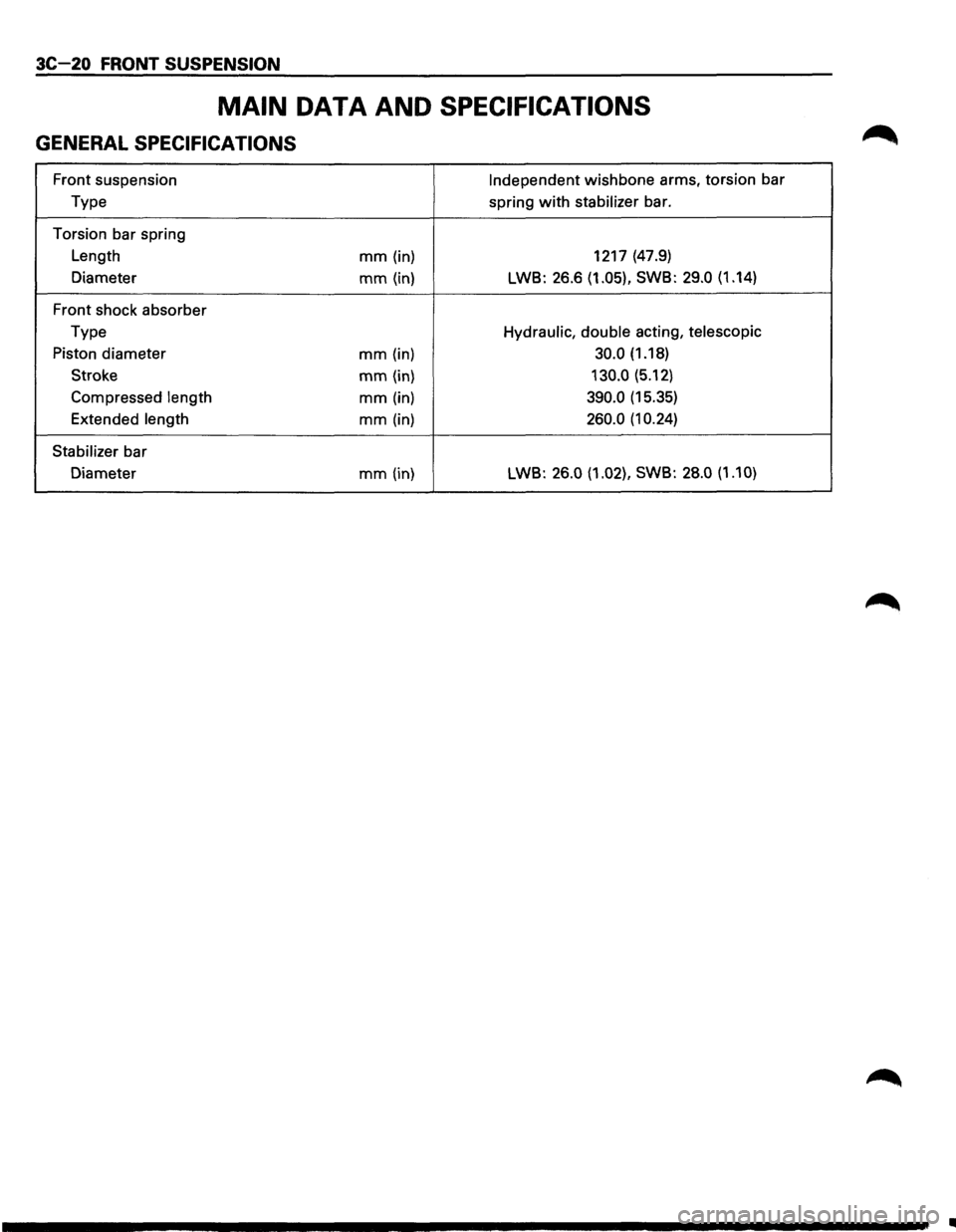
MAIN DATA AND SPECIFICATIONS
GENERAL SPECIFICATIONS
Front suspension Independent wishbone arms, torsion bar
Type spring
with stabilizer bar.
Torsion bar spring
Length
mm (in) 1217
(47.9)
Diameter
mm (in) LWB: 26.6 (1.05), SWB: 29.0 (1.14)
Front shock absorber
Type
Hydraulic, double acting, telescopic
Piston diameter mm (in) 30.0 (1.18)
Stroke
mm (in) 130.0 (5.12)
Compressed
length mm (in) 390.0 (15.35)
Extended
length mm (in) 260.0 (1 0.24)
Stabilizer
bar
Diameter
mm (in) LWB: 26.0 (1.02),
SWB: 28.0 (1.10)
•
Page 185 of 1928
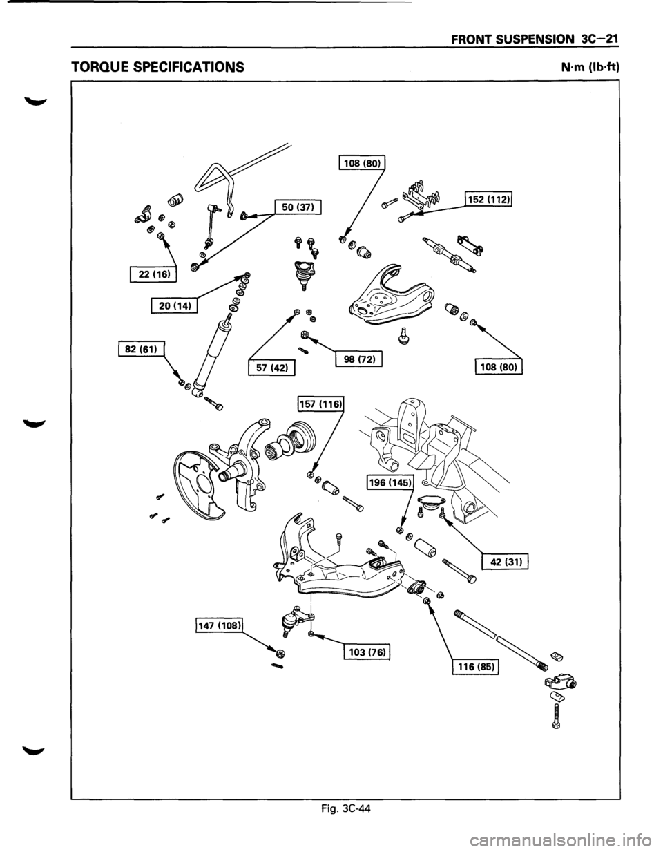
TORQUE SPECIFICATIONS
Fig. 3C-44
FRONT SUSPENSION 3C-21
N·m (lb·ft)
' 116(85)~ ~
~
~
!
Page 186 of 1928
3C 22 FRONT SUSPENSION
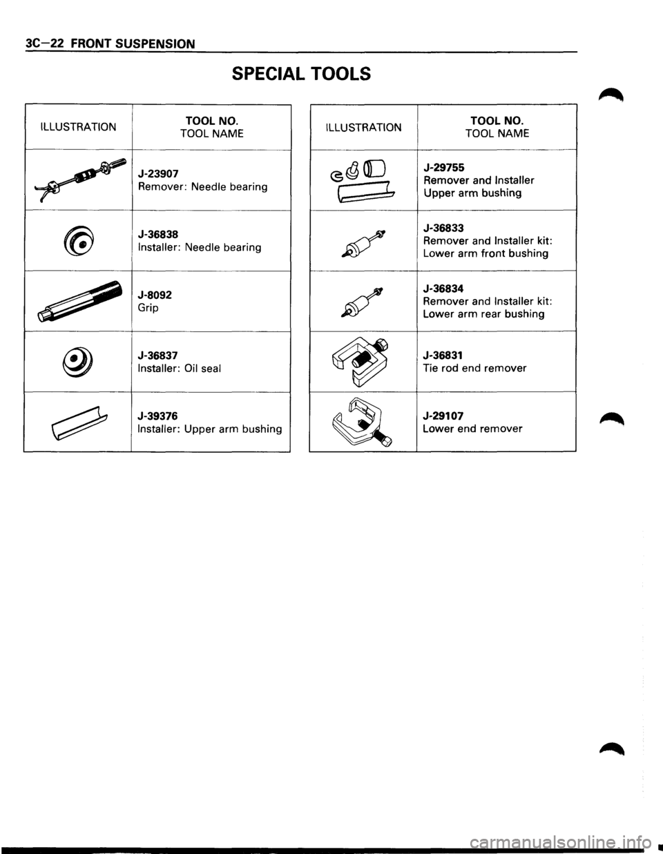
SPECIAL TOOLS
ILLUSTRATION TOOL NO.
TOOL NAME ILLUSTRATION TOOL NO.
TOOL NAME
~
J-23907
Remover: Needle bearing
<5~ ([] J-29755
Remover and Installer
~ ~ Upper arm bushing
@
J-36838
Installer: Needle bearing ~
J-36833
Remover and Installer kit:
Lower arm
front bushing
~
J-8092
Grip ;6/
J-36834
Remover and Installer kit:
Lower arm rear bushing
@
J-36837
Installer: Oil seal
~
J-36831
Tie rod end remover
~
J-39376
Installer: Upper arm bushing
~
J-29107
Lower end remover
•
Page 187 of 1928
REAR SUSPENSION 30-1
SECTION 30
REAR SUSPENSION
WCAUTION:
VI When fasteners are removed, always reinstall them at the same location from which they were removed. If a
fastener needs to be
replaced, use the correct part number fastener for that application. If the correct part
number fastener is
not available, a fastener of equal size and strength (or stronger) may be used. Fasteners
that are
not reused, and those requiring thread locking compound, will be called out. The correct torque
value must be used when installing fasteners that require it. If the above conditions are not followed, parts or
system damage could result.
CONTENTS
General Description . . . . . . . . . . . . . . . . . . . . 3D-2
On-Vehicle Service .................... 3D-3
Coil Spring . .
. . . . . . . . . . . . . . . . . . . . . . . 3D· 3
Shock
Absorber . . . . . . . . . . . . • . . . . . . . . 3D-5
Trailing Link . .
. . . . . . . . . . . . . . . . . . . . . . 3D-6
Center
Link . . • . . . . . . . . . . • . . . . . . . . . . . 3D-8
Lateral Rod ......................... 3D-1 0
Stabilizer Bar ........................ 3D-11
Main Data and Specifications ............ 3D-12
General Specifications ................ 3D-12
Torque Specifications
................ 30-13
Special Tools .......................... 3D-13
Page 188 of 1928
30-2 REAR SUSPENSION
GENERAL DESCRIPTION
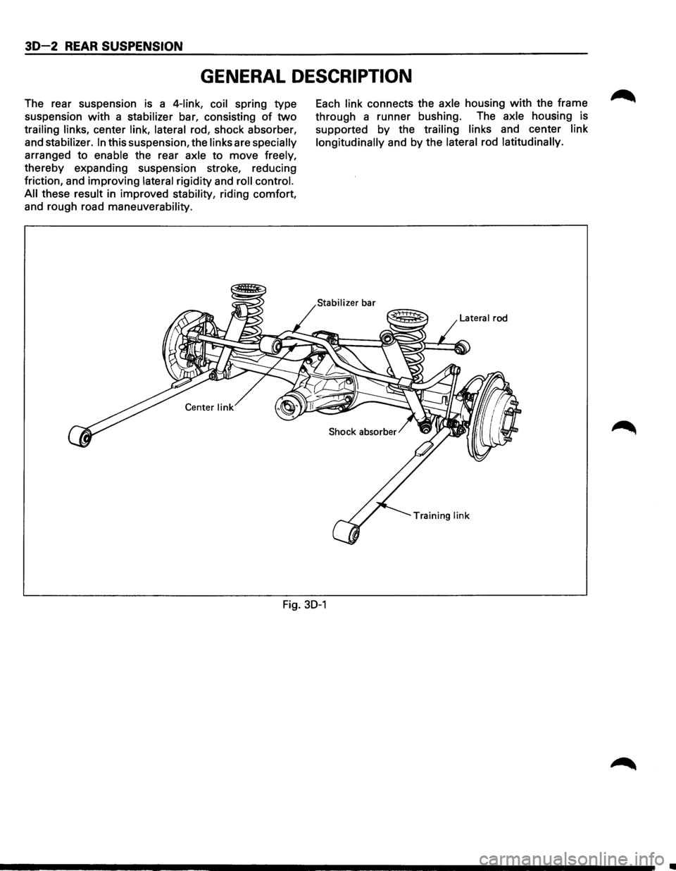
The rear suspension is a 4-link, coil spring type
suspension
with a stabilizer bar, consisting of two
trailing links, center link, lateral rod, shock absorber,
and
stabilizer. In this suspension, the links are specially
arranged to enable the rear axle to move freely,
thereby expanding suspension stroke, reducing
friction, and improving
lateral rigidity and roll control.
All
these result in improved stability, riding comfort,
and rough road
maneuverability.
Each link connects the axle housing with the frame
through a runner bushing. The
axle housing is
supported
by the trailing links and center link
longitudinally
and by the lateral rod latitudinally.
Lateral rod
Training
link
Fig. 30-1
•
Page 189 of 1928
REAR SUSPENSION 30-3
ON-VEHICLE SERVICE
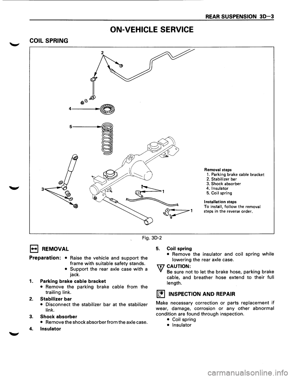
COIL SPRING
3
Removal steps
1. Parking brake cable bracket 2. Stabilizer bar
3. Shock absorber
4. Insulator 5. Coil spring
Installation steps
To install,
follow the removal
steps in the reverse order.
Fig. 30-2
E) REMOVAL
Preparation: • Raise the vehicle and support the
frame
with suitable safety stands.
• Support the rear axle case with a
jack.
1. Parking brake cable bracket
• Remove the parking brake cable from the
trailing link.
2. Stabilizer bar
• Disconnect the stabilizer bar at the stabilizer
link.
3. Shock absorber
• Remove the shock absorber from the axle case.
4. Insulator
5. Coil spring
• Remove the insulator and coil spring while
lowering
the rear axle case.
U7 CAUTION:
VI Be sure not to let the brake hose, parking brake
cable, and breather hose extend to their full
length.
(L!] INSPECTION AND REPAIR
Make necessary correction or parts replacement if
wear, damage, corrosion or any other abnormal
condition are found through inspection.
• Coil spring
• Insulator
Page 190 of 1928
30-4 REAR SUSPENSION
I••IINSTALLATION
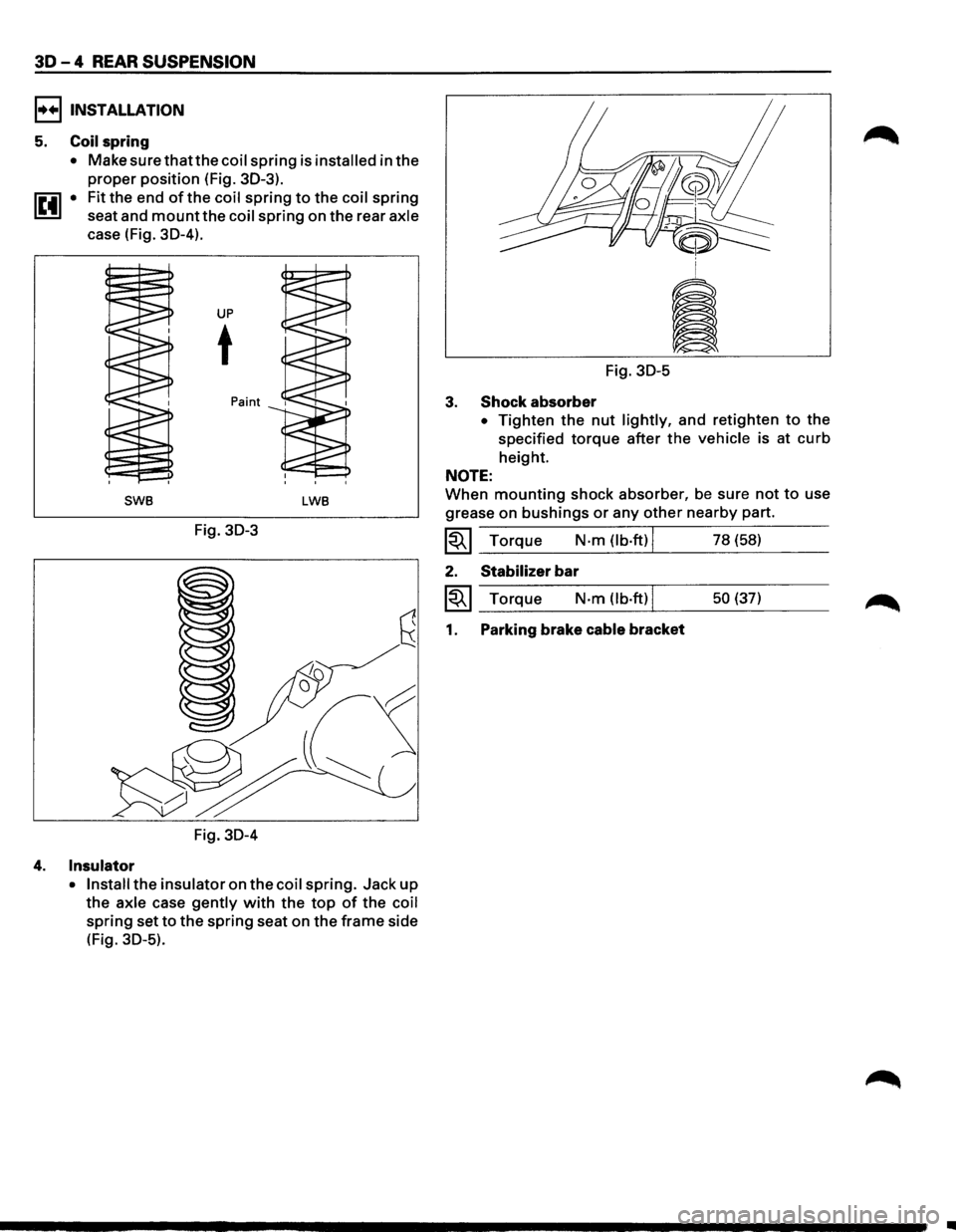
5. Coil spring
• Make surethatthecoil spring is installed in the
proper position (Fig. 30-3).
1~41 • Fit the end of the coil spring to the coil spring
seat and
mount the coil spring on the rear axle
case (Fig. 30-4).
UP
t
Paint
SWB LWB
Fig. 30-3
Fig. 30-4
4. Insulator
• Install the insulator on the coil spring. Jack up
the axle case gently with the top of the coil
spring set to the spring seat on the frame side
(Fig.
30-5).
Fig. 30-5
3. Shock absorber
• Tighten the nut lightly, and retighten to the
specified
torque after the vehicle is at curb
height.
NOTE:
When mounting shock absorber, be sure not to use
grease on
bushings or any other nearby part.
~~~ Torque N·m (lb.ft) I 78 (58)
2. Stabilizer bar
~~~ Torque N·m (lb·ft) I 50 (37)
1. Parking brake cable bracket
•