ISUZU TROOPER 1995 Workshop Manual
Manufacturer: ISUZU, Model Year: 1995, Model line: TROOPER, Model: ISUZU TROOPER 1995Pages: 1928
Page 151 of 1928
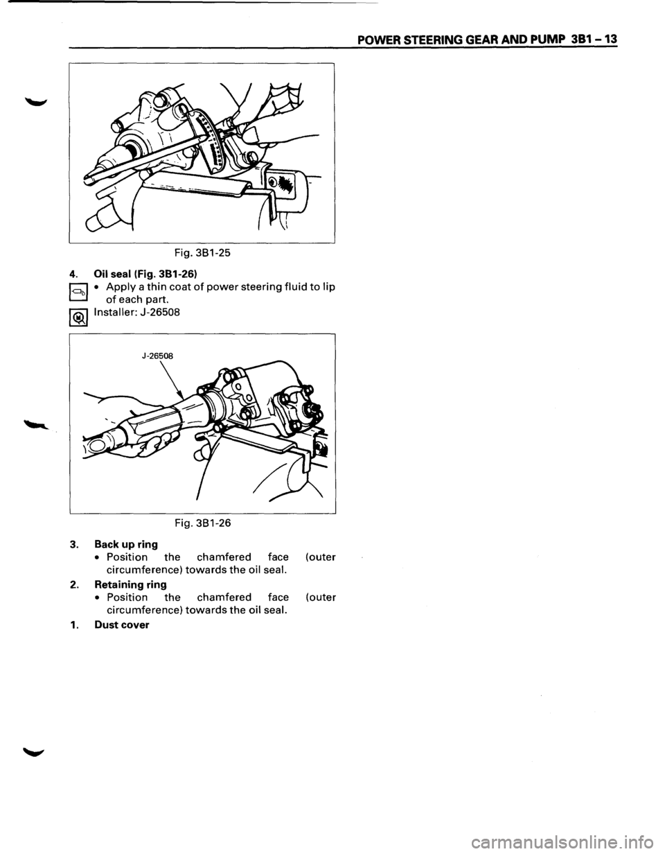
Fig. 381-25
4. Oil seal (Fig. 381-26)
~ • Apply a thin coat of power steering fluid to lip
D of each part.
l®..llnstaller: J-26508
J-26508
Fig. 381-26
3. Back up ring
• Position the chamfered face (outer
circumference) towards the oil seal.
2. Retaining ring
• Position the chamfered face (outer
circumference) towards the oil seal.
1. Dust cover
POWER STEERING GEAR AND PUMP 381 -13
Page 152 of 1928
381-14 POWER STEERING GEAR AND PUMP
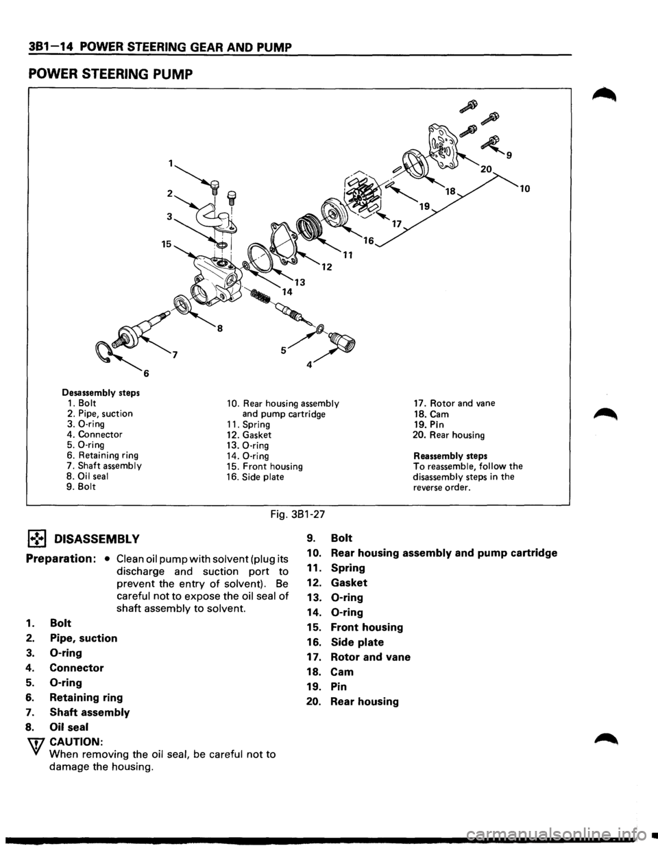
POWER STEERING PUMP
Desassembly steps 1. Bolt 10. Rear housing assembly 2. Pipe, suction
and pump cartridge
3. 0-ring 11. Spring 4. Connector
12. Gasket
5. 0-ring 13. 0-ring 6. Retaining ring
14. 0-ring 7. Shaft assembly 15. Front housing
8. Oil seal 16. Side plate 9. Bolt
Fig. 381-27
l•!•l DISASSEMBLY 9. Bolt
17. Rotor and vane
18.Cam 19. Pin 20. Rear housing
Reassembly steps
10
To reassemble, follow the disassembly steps in the
reverse order.
Preparation: • Clean oil pump with solvent (plug its
discharge and suction
port to
prevent the entry of solvent). Be
careful not to expose the oil seal of
shaft assembly to solvent.
1 0. Rear housing assembly and pump cartridge
1. Bolt
2. Pipe, suction
3. 0-ring
4. Connector
5. 0-ring
6. Retaining ring
7. Shaft assembly
8. Oil seal
'\fl CAUTION:
~ When removing the oil seal, be careful not to
damage the housing.
11. Spring
12. Gasket
13. 0-ring
14. 0-ring
15. Front housing
16. Side
plate
17. Rotor and vane
18.
Cam
19. Pin
20. Rear housing
•
Page 153 of 1928
[1!) INSPECTION AND REPAIR
Make all necessary adjustments, repairs, and part
replacements
if wear, damage, or other problems are
discovered during inspection.
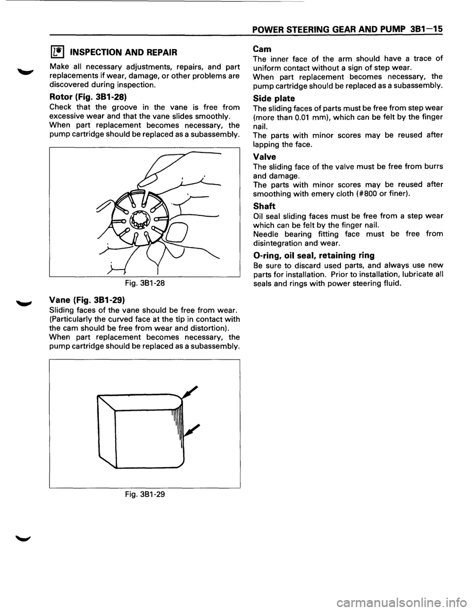
Rotor (Fig. 381-28)
Check that the groove in the vane is free from
excessive wear and that the vane slides smoothly.
When part replacement becomes necessary, the
pump cartridge
should be replaced as a subassembly.
Fig. 381-28
Vane (Fig. 381-29)
Sliding faces of the vane should be free from wear.
(Particularly the curved face at the tip in contact with
the cam should be free from wear and distortion).
When part
replacement becomes necessary, the
pump cartridge should be replaced as a subassembly.
Fig. 381-29
POWER STEERING GEAR AND PUMP 381-15
Cam
The inner face of the arm should have a trace of
uniform contact without a sign of step wear.
When part
replacement becomes necessary, the
pump cartridge should be replaced as a subassembly.
Side plate
The sliding faces of parts must be free from step wear
(more than 0.01 mm), which can be felt by the finger
nail.
The parts with minor scores may be reused after
lapping the face.
Valve
The sliding face of the valve must be free from burrs
and damage.
The parts
with minor scores may be reused after
smoothing
with emery cloth (#800 or finer).
Shaft
Oil seal sliding faces must be free from a step wear
which can be felt by the finger nail.
Needle
bearing fitting face must be free from
disintegration and wear.
0-ring, oil seal, retaining ring
Be sure to discard used parts, and always use new
parts for installation. Prior to installation, lubricate all
seals
and rings with power steering fluid.
Page 154 of 1928
381-16 POWER STEERING GEAR AND PUMP
l•!•l REASSEMBL V
20. Rear housing
19. Pin
18. Cam
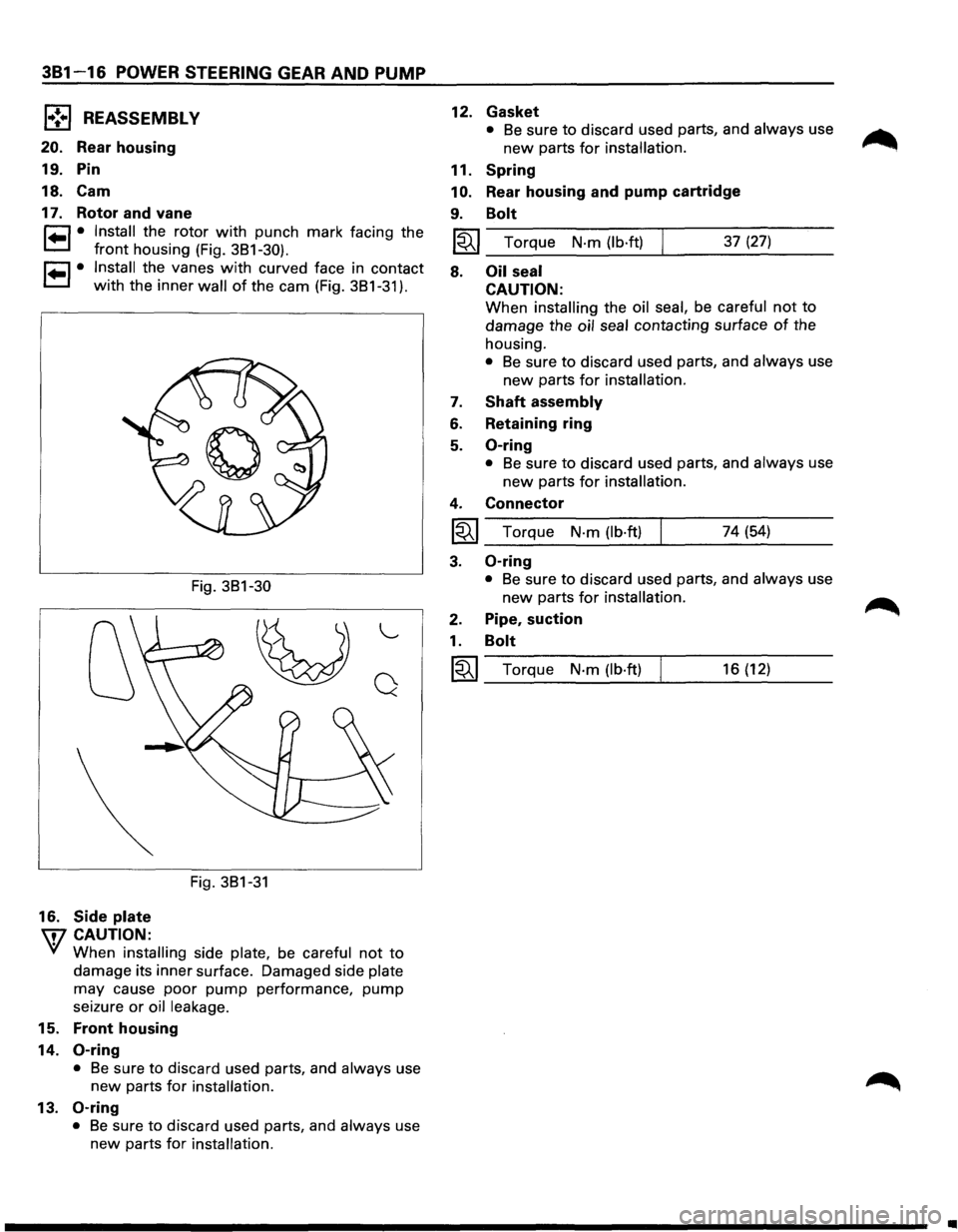
17. Rotor and vane
r=1 • Install the rotor with punch mark facing the
t=1 front housing (Fig. 3B1-30).
r=1 • Install the vanes with curved face in contact
t=1 with the inner wall of the cam (Fig. 3B1-31 ).
16. Side plate
\fl CAUTION:
Fig. 3B1-30
~
Fig. 3B1-31
"---
Q
'if When installing side plate, be careful not to
damage its inner surface. Damaged side plate
may cause poor pump performance, pump
seizure or oil leakage.
15. Front housing
14.
0-ring
• Be sure to discard used parts, and always use
new parts for installation.
13. 0-ring
• Be sure to discard used parts, and always use
new parts
for installation.
12.
11.
10.
9.
Gasket
• Be sure to discard used parts, and always use
new parts for installation.
Spring
Rear housing and pump cartridge
Bolt
l~I_T_o_rq_u_e_N_·_m_(_lb_·f_tl____. ___ 3_7_(2_7_) __ _
8.
7.
6.
5.
4.
~
3.
2.
1.
~
Oil seal
CAUTION:
When installing the oil seal, be careful not to
damage the oil seal contacting surface of the
housing.
• Be sure to discard used parts, and always use
new parts for installation.
Shaft assembly
Retaining ring
0-ring
• Be sure to discard used parts, and always use
new parts for installation.
Connector
Torque N·m (lb·ft) 74 (54)
0-ring
• Be sure to discard used parts, and always use
new parts for installation.
Pipe, suction
Bolt
Torque N·m (lb·ft) 16 (12)
..
Page 155 of 1928
POWER STEERING GEAR AND PUMP 381-17
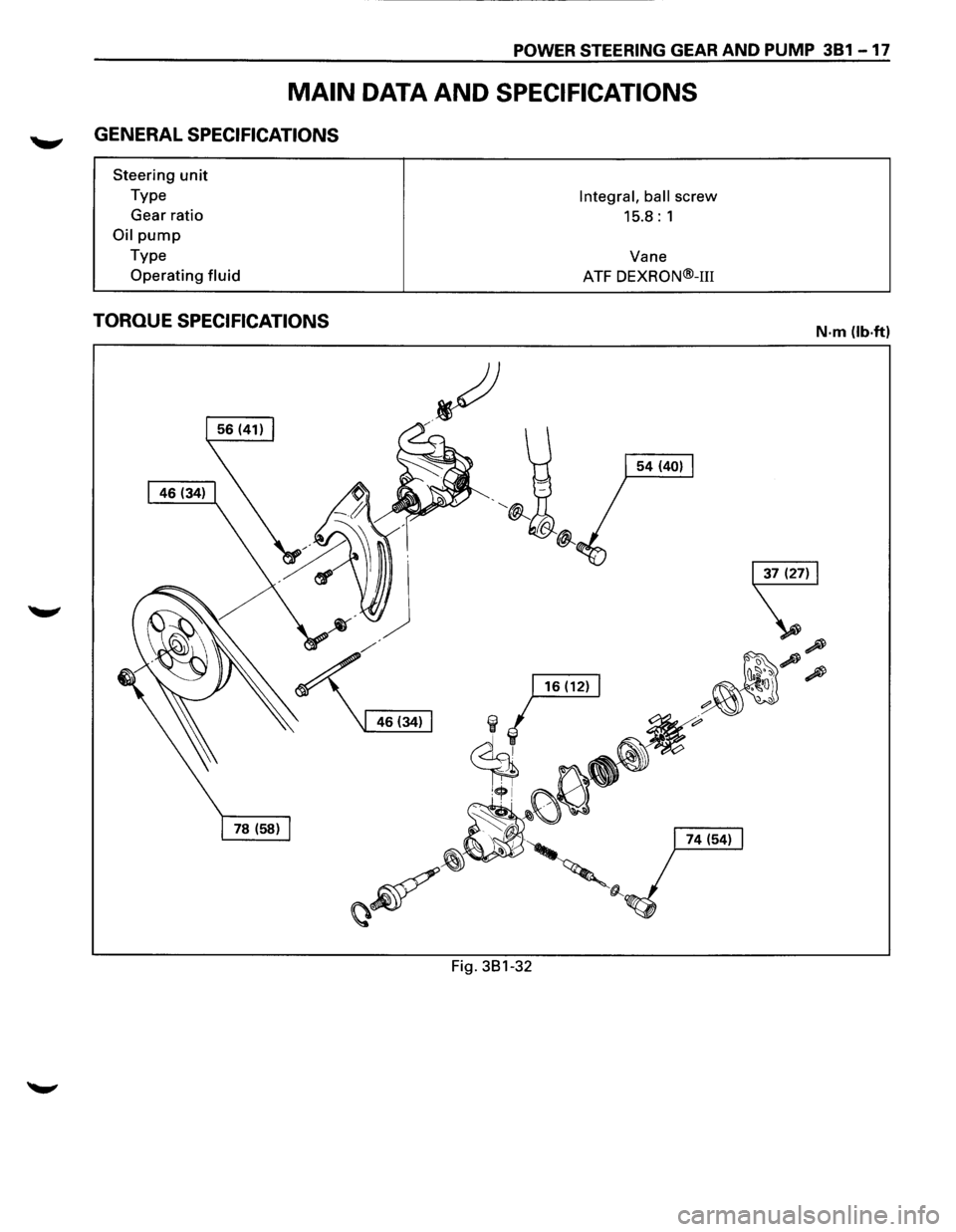
MAIN DATA AND SPECIFICATIONS
GENERAL SPECIFICATIONS
Steering unit
Type
Gear ratio
Oil pump
Type
Operating
fluid
TORQUE SPECIFICATIONS
Fig. 381-32
Integral, ball screw
15.8: 1
Vane
ATF
DEXRON®-m
N·m (lb.ft)
Page 156 of 1928
381-18 POWER STEERING GEAR AND PUMP
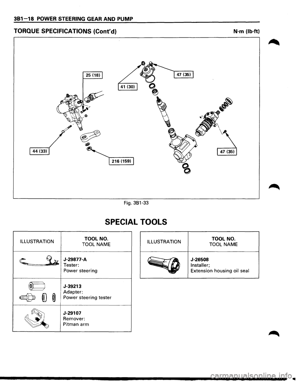
TORQUE SPECIFICATIONS (Cont'd) N·m (lb·ft)
25 (18)
Fig. 381-33
SPECIAL TOOLS
ILLUSTRATION TOOL
NO.
TOOL NAME ILLUSTRATION TOOL
NO.
TOOL NAME
~
J-29877-A
Tester: Power steering
~
J-26508
Installer;
Extension housing oil seal
~ J-39213
~ ID ®
Adapter:
Power steering tester
~
J-29107
Remover:
Pitman arm
Page 157 of 1928
STEERING LINKAGE 383-1
SECTION 383
STEERING LINKAGE
w CAUTION:
• When fasteners are removed, always reinstall them at the same location from which they were removed. If a
fastener needs
to be replaced, use the correct part number fastener for that application. If the correct part
number fastener is not available, a fastener of equal size and strength (or stronger) may be used. Fasteners
that are not reused, and those requiring thread locking compound, will be called out. The correct torque
value must be used when installing fasteners that require it. If the above conditions are not followed, parts or
system damage could result.
CONTENTS
General Description . . . . . . . . . . . . . . . . . . . . 383-1
On-Vehicle Service .................... 383-2
Center Track Rod Assembly . . . . . . . . . . . 383-2
Outer Track Rod Assembly . . . . . . . . . . . . 383-4
Relay Lever . . . . . . . . . . . . . . . . . . . . . . . . . 383-6 Main
Data
and Specifications ............ 383-8
Torque Specifications
................ 383-8
Special Tools .......................... 383-8
GENERAL DESCRIPTION
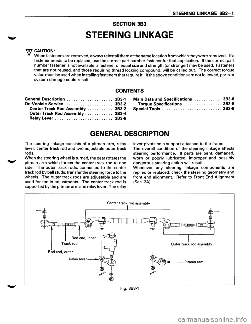
The steering linkage consists of a pitman arm, relay
lever,
center track rod and two adjustable outer track
rods.
When the steering
wheel is turned, the gear rotates the
pitman arm
which forces the center track rod to one
side. The outer track rods, connected to the center
track rod
by ball studs, transfer the steering force to the
wheels. The outer track rods are adjustable and are
used
for toe-in adjustments. The center track rod is
supported
by the pitman arm and relay lever. The relay lever
pivots
on a support attached to the frame.
The
overall condition of the steering linkage affects
steering performance.
If parts are bent, damaged,
worn or poorly lubricated, improper and possibly
dangerous steering action will result.
Whenever any steering linkage components are
replied or replaced, check the steering geometry and
front end alignment. Refer to Front End Alignment
(Sec. 3A).
Center track rod assembly
Rod end, inner
Track rod
Rod end, outer
Relay lever---~·--:;:::jo
I
I Outer track rod assembly
Fig. 383-1
Page 158 of 1928
383-2 STEERING LINKAGE
ON-VEHICLE SERVICE
CENTER TRACK ROD ASSEMBL V
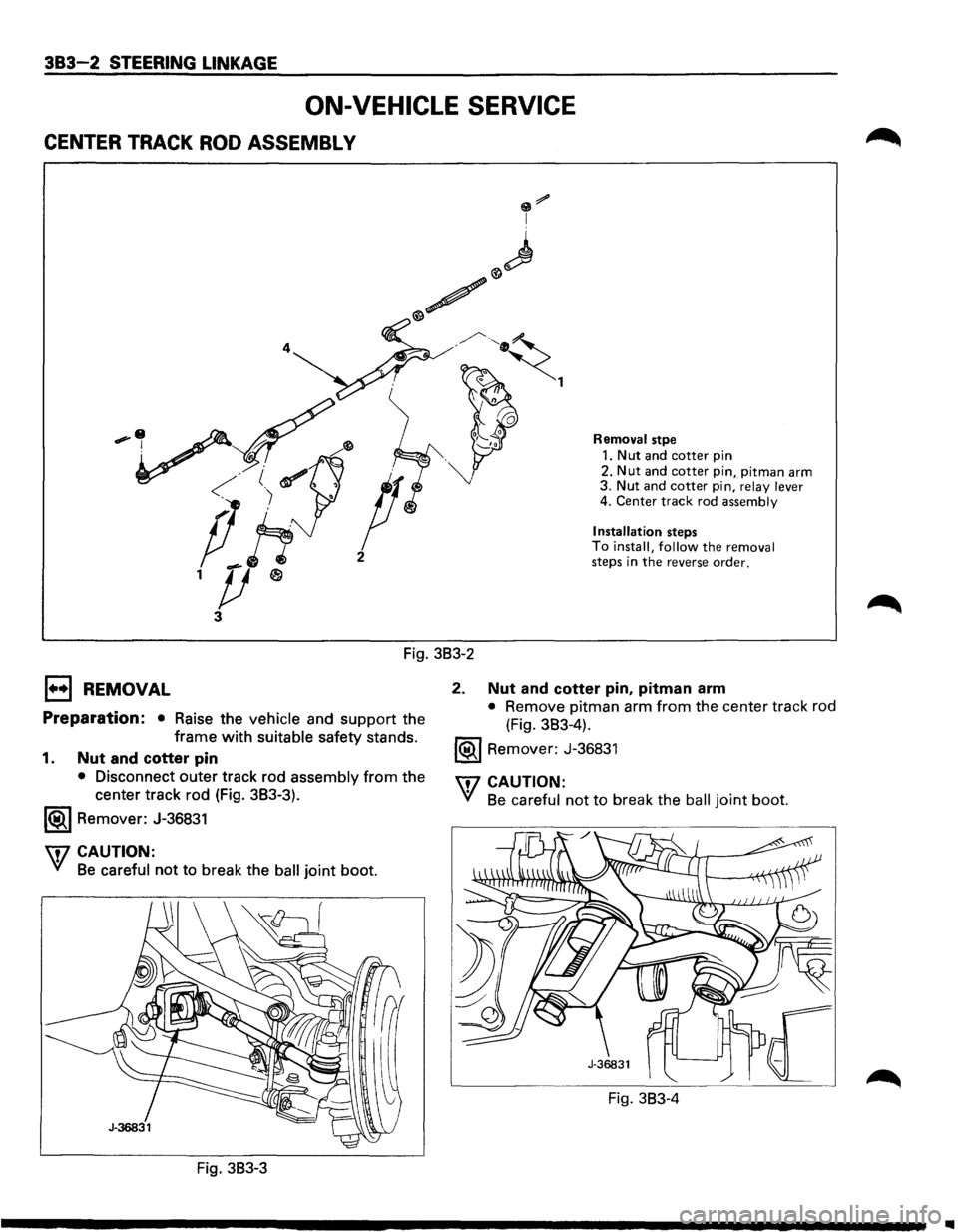
Removal stpe
1. Nut and cotter pin
2.
Nut and cotter pin, pitman arm 3. Nut and cotter pin, relay lever 4. Center track rod assembly
Installation
steps To install, follow the removal steps in the reverse order.
Fig. 3B3-2
1••1 REMOVAL
Preparation: • Raise the vehicle and support the
frame
with suitable safety stands.
1. Nut and cotter pin
• Disconnect outer track rod assembly from the
center track rod (Fig. 3B3-3).
1®.1 Remover: J-36831
U7 CAUTION:
V/ Be careful not to break the ball joint boot.
Fig. 3B3-3
2. Nut and cotter pin, pitman arm
• Remove pitman arm from the center track rod
(Fig. 3B3-4).
1®1 Remover: J-36831
\f7 CAUTION:
VI Be careful not to break the ball joint boot.
Fig. 3B3-4
..
Page 159 of 1928
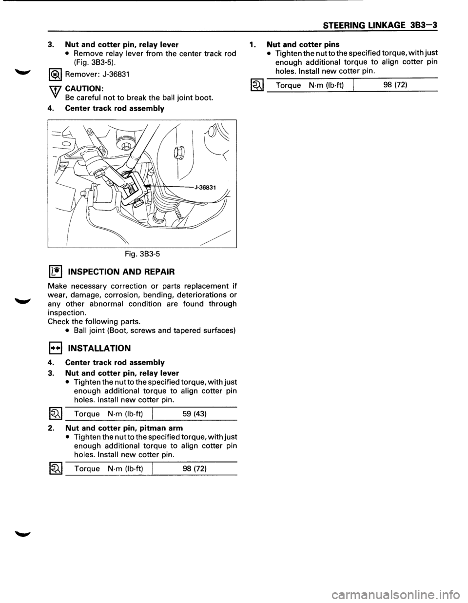
3. Nut and cotter pin, relay lever
• Remove relay lever from the center track rod
(Fig. 3B3-5).
1®.1 Remover: J-36831
\flCAUTION:
'VI Be careful not to break the ball joint boot.
4. Center track rod assembly
Fig. 3B3-5
Wtl INSPECTION AND REPAIR
~
Make necessary correction or parts replacement if
wear, damage, corrosion, bending, deteriorations or
any other abnormal condition are found through
inspection.
Check the
following parts.
• Ball joint (Boot, screws and tapered surfaces)
1••1 INSTALLATION
4. Center track rod assembly
3. Nut and cotter pin, relay lever
• Tighten the nutto the specified torque, with just
enough additional torque to align cotter pin
holes. Install new cotter pin.
~~~ Torque N·m (lb·ft) 59 (43)
2. Nut and cotter pin, pitman arm
• Tighten the nut to the specified torque, with just
enough additional torque to align cotter pin
holes. Install new cotter pin.
1~1 Torque N-m (lb·ft) 98 (72)
1.
STEERING LINKAGE 383-3
Nut and cotter pins
• Tighten the nutto the specified torque, with just
enough
additional torque to align cotter pin
holes. Install new cotter pin.
I~I_T_o_rq..;...u_e_N_·m_(l_b_·ft_) ___t_ ___ 9_8_(7_2_) __ _
Page 160 of 1928
383 - 4 STEERING LINKAGE
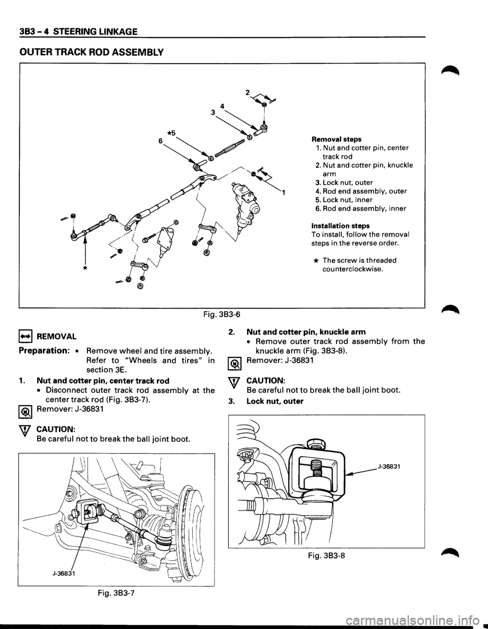
OUTER TRACK ROD ASSEMBLY
1+•1 REMOVAL
Fig. 3B3-6
2.
Preparation: • Remove wheel and tire assembly.
Refer to "Wheels and tires" in
section
3E. ~
Removal steps
1. Nut and cotter pin, center
track rod
2. Nut and cotter pin, knuckle
arm
3. Lock nut, outer
4. Rod end assembly, outer
5. Lock nut, inner
6. Rod end assembly, inner
Installation steps
To install, follow the removal
steps in the reverse order.
* The screw is threaded
counterclockwise.
Nut and cotter pin, knuckle arm
• Remove outer track rod assembly from the
knuckle arm (Fig. 3B3-8).
Remover: J-36831
1. Nut and cotter pin, center track rod
• Disconnect outer track rod assembly at the
center track rod (Fig. 3B3-7).
'\f CAUTION:
Be careful not to break the ball joint boot.
3. Lock nut, outer Remover: J-36831
CAUTION:
Be careful not to break the ball joint boot.
J-36831
Fig. 3B3-8
Fig. 3B3-7