ISUZU TROOPER 1995 Workshop Manual
Manufacturer: ISUZU, Model Year: 1995, Model line: TROOPER, Model: ISUZU TROOPER 1995Pages: 1928
Page 191 of 1928
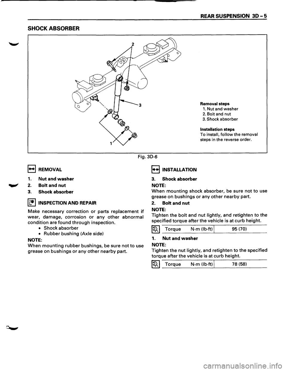
SHOCK ABSORBER
REAR SUSPENSION 30-5
Removal steps
1. Nut and washer
2. Bolt and nut
3. Shock absorber
Installation steps
To
install, follow the removal
steps in the reverse order.
1++1 REMOVAL
1. Nut and washer
2. Bolt and nut
Fig. 30-6
I••IINSTALLATION
3. Shock absorber
NOTE:
3. Shock absorber
IL•IINSPECTION AND REPAIR
Make necessary correction or parts replacement if
wear, damage, corrosion or any other abnormal
condition are found through inspection.
• Shock absorber
• Rubber bushing (Axle side)
NOTE:
When mounting rubber bushings, be sure not to use
grease
on bushings or any other nearby part.
When mounting shock absorber, be sure not to use
grease
on bushings or any other nearby part.
2. Bolt and nut
NOTE:
Tighten the bolt and nut lightly, and retighten to the
specified torque after the vehicle is at curb height.
~~~ Torque N·m (lb·ftl J 95 (70)
1. Nut and washer
NOTE:
Tighten the nut lightly, and retighten to the specified
torque after the vehicle is at curb height.
~~~ Torque N·m (lb·ftl J 78 (58)
Page 192 of 1928
···------
30-6 REAR SUSPENSION
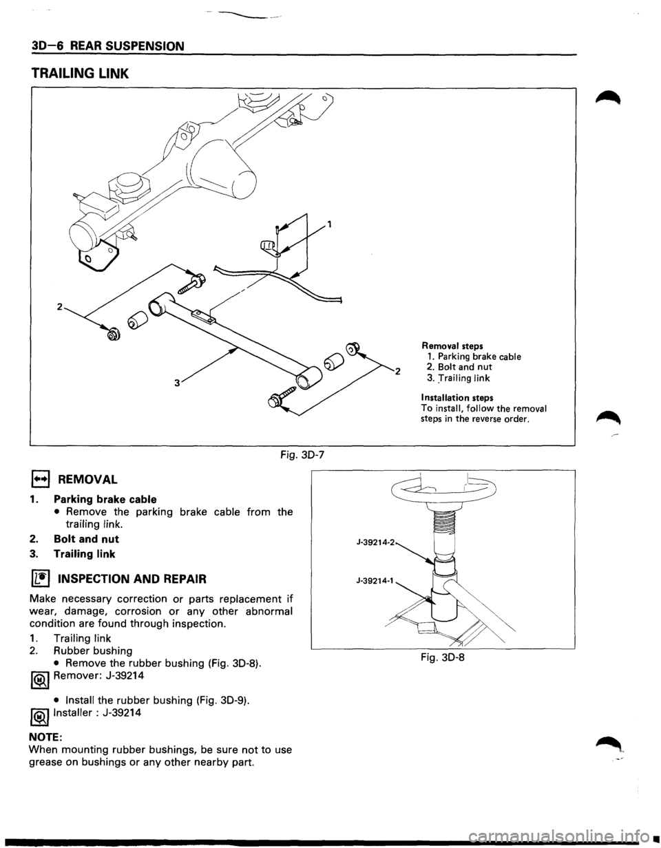
TRAILING LINK
2
Fig. 30-7
l••l REMOVAL
1. Parking brake cable
• Remove the parking brake cable from the
trailing link.
2. Bolt and nut
3. Trailing link
IL•I INSPECTION AND REPAIR
Make necessary correction or parts replacement if
wear, damage, corrosion or any other abnormal
condition are found through inspection.
1. Trailing link
2. Rubber bushing
• Remove the rubber bushing (Fig. 30-8).
1®..1 Remover: J-39214
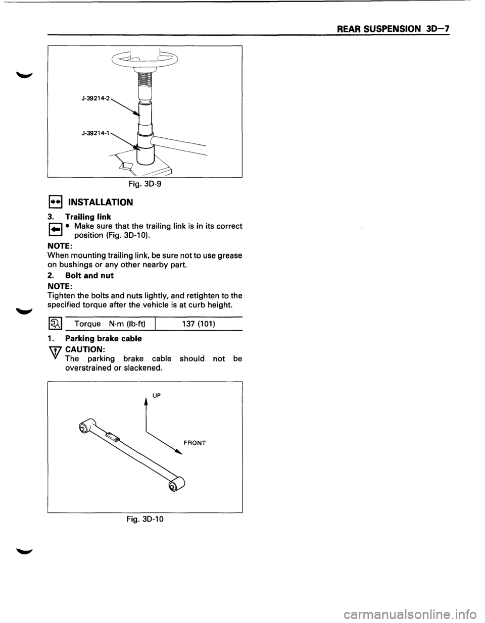
• Install the rubber bushing (Fig. 30-9).
!®I Installer : J-39214
NOTE:
When mounting rubber bushings, be sure not to use
grease on bushings
or any other nearby part.
2
J-39214·2
J-39214·1
Removal steps 1. Parking brake cable 2. Bolt and nut
3. :rrailing link
I
nsta llatio n steps
To install, follow the removal steps in the reverse order. ~
..----- 1-~
Fig. 30-8
•
Page 193 of 1928
J-39214-2 J-39214-1
Fig. 30-9
1••1 INSTALLATION
3. Trailing link
~ • Make sure that the trailing link is in its correct
1.=.1 position (Fig. 30-1 0).
NOTE:
When mounting trailing link, be sure not to use grease
on bushings or any other nearby part.
2. Bolt and nut
NOTE:
Tighten the bolts and nuts lightly, and retighten to the
specified torque after the
vehicle is at curb height.
1~1 Torque N·m (lb·ft)
1. Parking brake cable
W CAUTION:
137 (101)
VI The parking brake cable should not be
overstrained or
slackened.
UP
Fig. 30-10
REAR SUSPENSION 30-7
Page 194 of 1928
30-8 REAR SUSPENSION
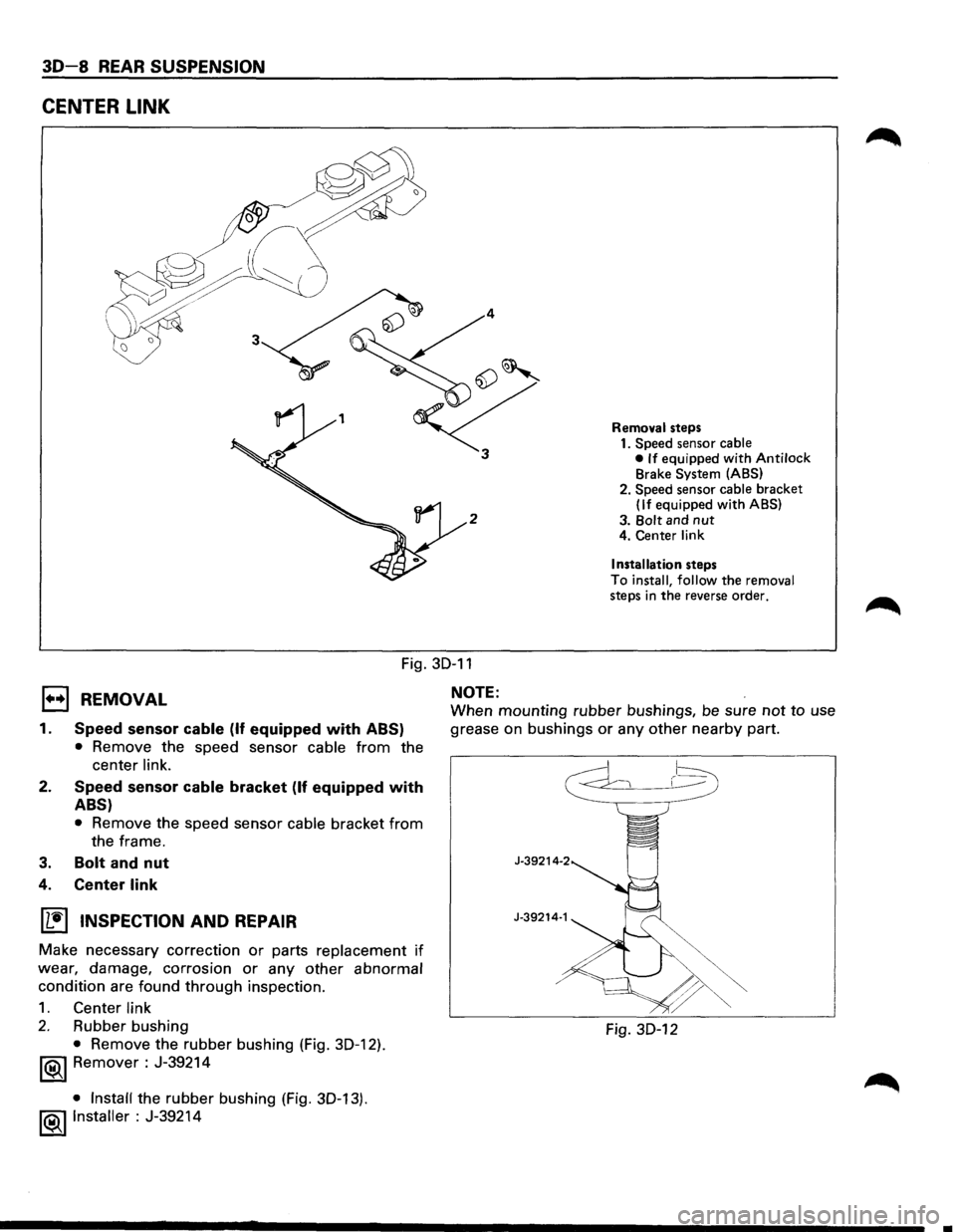
CENTER LINK
2
Removal steps
1. Speed sensor cable
• If equipped with Antilock Brake System (ABS)
2. Speed sensor
cable bracket (If equipped with ABS)
3.
Bolt and nut 4. Center link
Installation
steps
To
install, follow the removal steps in the reverse order.
1•+1 REMOVAL
Fig. 30-11
NOTE:
1.
2.
3.
Speed sensor cable (If equipped with ABS)
• Remove the speed sensor cable from the
center
link.
Speed sensor cable bracket (If equipped with
ABS)
• Remove the speed sensor cable bracket from
the frame.
Bolt and nut
4. Center link
~ INSPECTION AND REPAIR
Make necessary correction or parts replacement if
wear, damage, corrosion or any other abnormal
condition are found through inspection.
1. Center link
2. Rubber bushing
• Remove the rubber bushing (Fig. 30-12).
1®1 Remover : J-39214
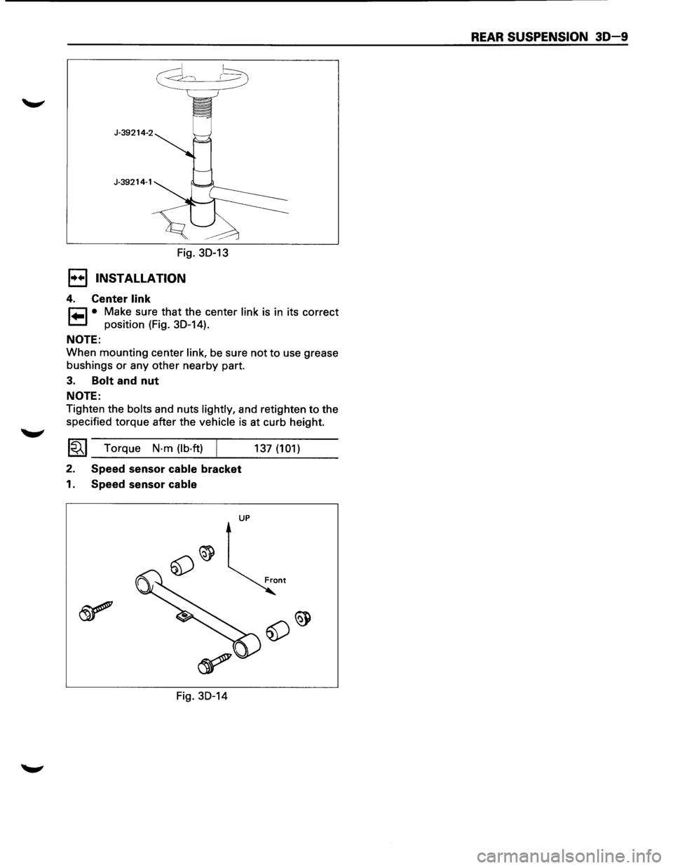
• Install the rubber bushing (Fig. 30-13).
!®..I Installer : J-39214
When mounting rubber bushings, be sure not to use
grease on bushings
or any other nearby part.
J-39214-2
J-39214·1
Fig. 30-12
..
Page 195 of 1928
r-:::::1 )--~
Fig. 30-13
I•+ I INSTALLATION
4. Center link
r=l • Make sure that the center link is in its correct
1.=.1 position (Fig. 30-14).
NOTE:
When mounting center link, be sure not to use grease
bushings
or any other nearby part.
3. Bolt and nut
NOTE:
Tighten the bolts and nuts lightly, and retighten to the
specified torque after the
vehicle is at curb height.
~~~ Torque N·m (lb·ft) /
2. Speed sensor cable bracket
1. Speed sensor cable
UP
Fig. 30-14 137
(101)
REAR SUSPENSION 30-9
Page 196 of 1928
30-10 REAR SUSPENSION
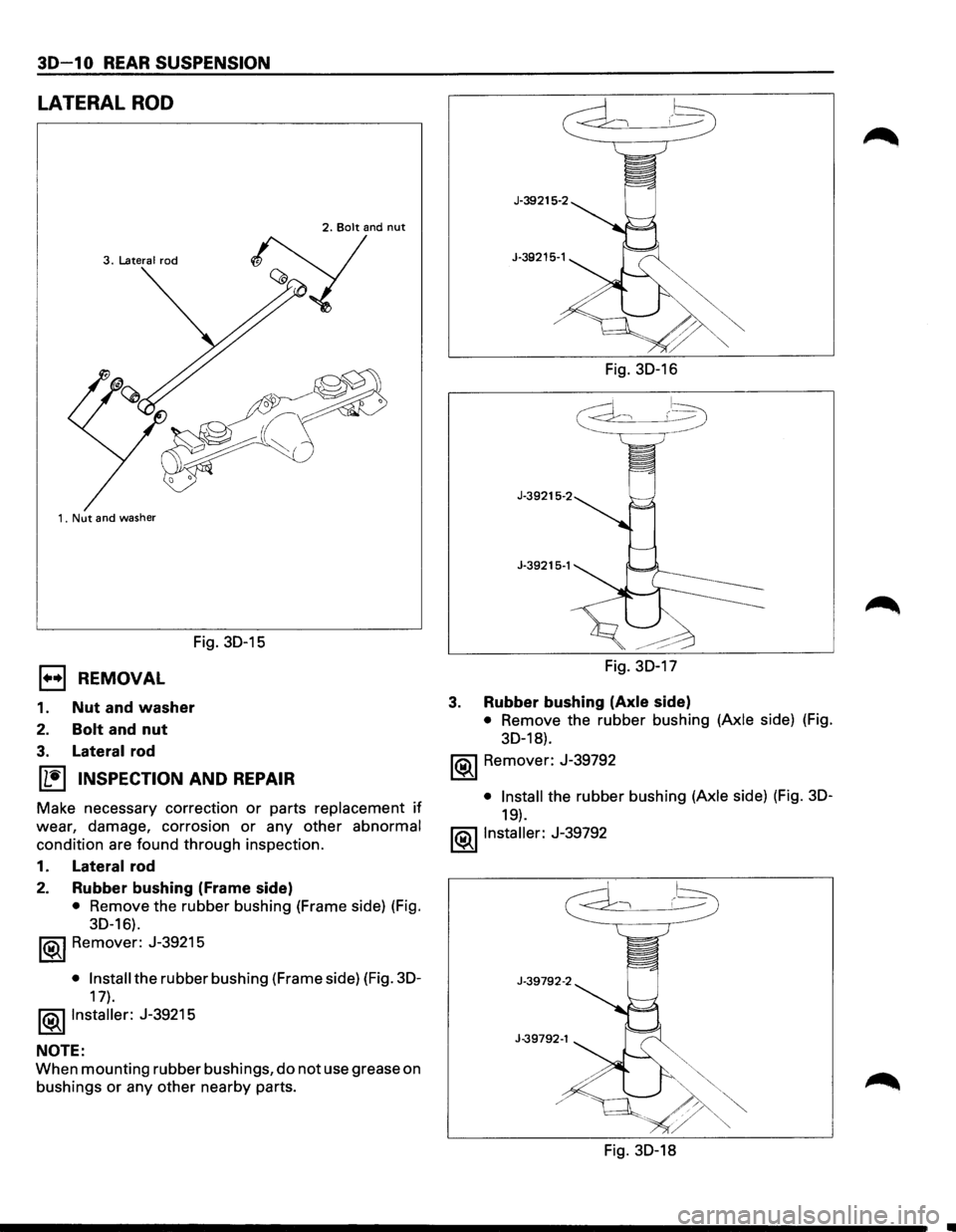
LATERAL ROD
3. Latera I rod
1. Nut
and washer
Fig. 30-15
EJ REMOVAL
1. Nut and washer
2. Bolt and nut
3. Lateral rod
~ INSPECTION AND REPAIR
Make necessary correction or parts replacement if
wear, damage, corrosion or any other abnormal
condition are found through inspection.
1.
Lateral rod
2. Rubber bushing (Frame side)
• Remove the rubber bushing (Frame side) (Fig.
30-16).
1®..1 Remover: J-39215
• Install the rubber bushing (Frame side) (Fig. 30-
17).
l®..llnstaller: J-39215
NOTE:
When mounting rubber bushings, do not use grease on
bushings
or any other nearby parts. Fig.
30-16
J-39215-2
J-39215·1
Fig. 30-17
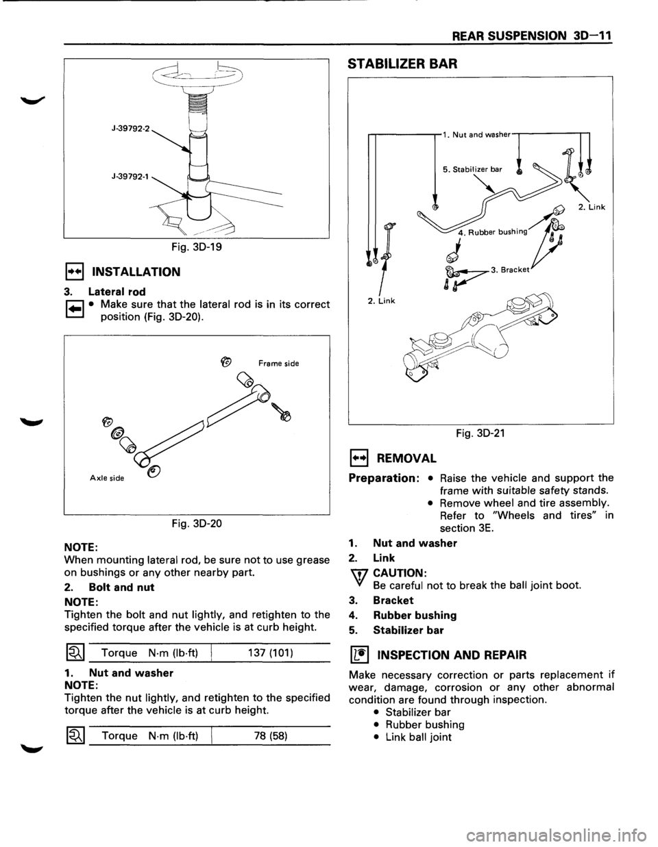
3. Rubber bushing (Axle side)
• Remove the rubber bushing (Axle side) (Fig.
30-18).
1®..1 Remover: J-39792
• Install the rubber bushing (Axle side) (Fig. 30-
19).
l®..llnstaller: J-39792
Fig. 30-18
Page 197 of 1928
J-39792-1
Fig. 30-19
1•+1 INSTALLATION
3. Lateral rod
~ • Make sure that the lateral rod is in its correct
~ position (Fig. 30-20).
Frame side
Axle side
Fig. 30-20
NOTE:
When mounting lateral rod, be sure not to use grease
on bushings
or any other nearby part.
2. Bolt and nut
NOTE:
Tighten the bolt and nut lightly, and retighten to the
specified torque after the
vehicle is at curb height.
~~~ Torque N·m (lb·ft)
1. Nut and washer
NOTE:
137 (101)
Tighten the nut lightly, and retighten to the specified
torque after the
vehicle is at curb height.
1~1 Torque N·m (lb·ft) 78 (58)
REAR SUSPENSION 30-11
STABILIZER BAR
2. Link
Fig. 30-21
EJ REMOVAL
Preparation: • Raise the vehicle and support the
frame
with suitable safety stands.
• Remove wheel and tire assembly.
Refer
to "Wheels and tires" in
section
3E.
1. Nut and washer
2. Link
\fl CAUTION:
VI Be careful not to break the ball joint boot.
3. Bracket
4. Rubber bushing
5. Stabilizer bar
[!] INSPECTION AND REPAIR
Make necessary correction or parts replacement if
wear, damage, corrosion or any other abnormal
condition are found through inspection.
• Stabilizer bar
• Rubber bushing
• Link ball joint
Page 198 of 1928
3D -12 REAR SUSPENSION
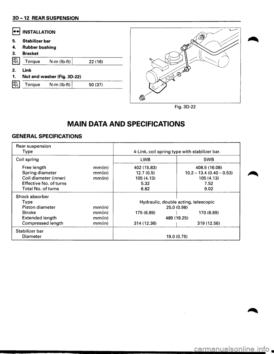
l+•liNSTALLATION
5. Stabilizer bar
4. Rubber bushing
3. Bracket
~~~ Torque N·m (lb.ft) I 22 (16)
2. Link
1. Nut and washer (Fig. 30-22)
~~~ Torque N-m (lb·ft) I 50 (37)
Fig.
30-22
MAIN DATA AND SPECIFICATIONS
GENERAL SPECIFICATIONS
Rear suspension
Type 4-Link, coil spring type with stabilizer bar.
Coil spring LWB SWB
Free
length mm(in) 402 (15.83) 408.5 (16.08)
Spring diameter mm(in) 12.7 (0.5) 10.2-13.4 (0.40-0.53)
Coil diameter (inner) mm(in) 105 (4.13) 105(4.13)
Effective No.
of turns 5.32 7.52
Total No. of turns 6.82 9.02
Shock absorber
Type Hydraulic, double acting, telescopic
Piston diameter mm(in) 25.0
(0.98)
Stroke
mm(in) 175 (6.89) I 170 (6.69)
Extended
length mm(in) 489 (19.25)
Compressed length mm(in) 314 (12.36) I 319 (12.56)
Stabilizer bar
Diameter 19.0 (0.75)
•
Page 199 of 1928
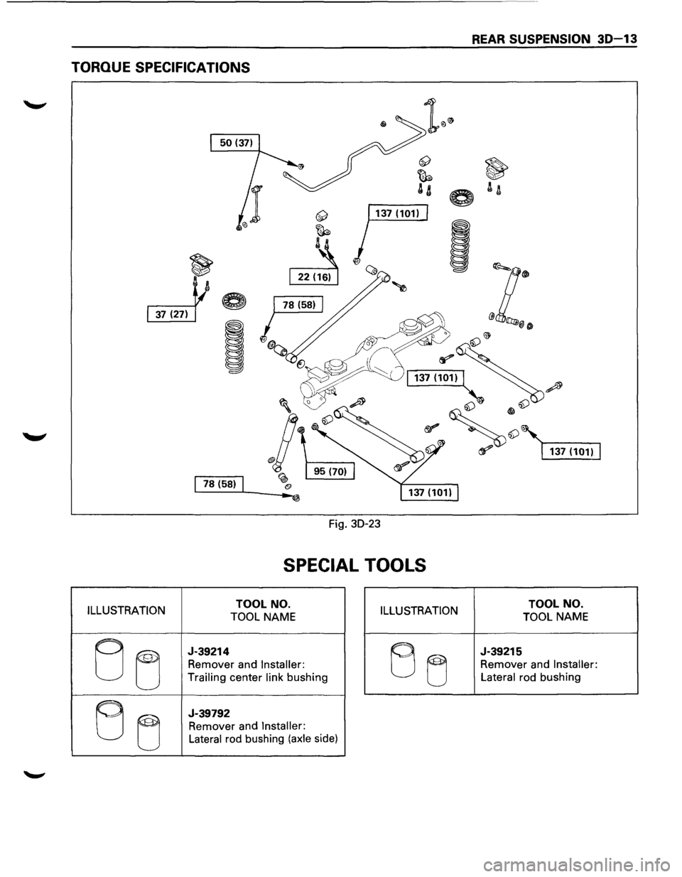
REAR SUSPENSION 30-13
TORQUE SPECIFICATIONS
1 1s (sa) 1
Fig. 30-23
SPECIAL TOOLS
ILLUSTRATION TOOL NO.
TOOL NAME ILLUSTRATION TOOL NO.
TOOL NAME
EJ ~
J-39214
Remover and Installer:
Trailing
center link bushing B u
J-39215
Remover and Installer:
Lateral
rod bushing
B u
J-39792
Remover and Installer:
Lateral
rod bushing (axle side)
Page 200 of 1928
MEMO