air condition ISUZU TROOPER 1995 Workshop Manual
[x] Cancel search | Manufacturer: ISUZU, Model Year: 1995, Model line: TROOPER, Model: ISUZU TROOPER 1995Pages: 1928
Page 835 of 1928
RESULTS OF INCORRECT OPERATION
An open or ground in the Ignition Control (I C) or bypass
circuits
will set a Diagnostic Trouble Code (DTC) 42 and
cause the engine
to run on the Ignition Control Module
(ICM)
timing.
The Engine
Control Module (ECM) uses information
from the Intake Air Temperature (IAT) and engine
coolant sensors in addition to revolution per minute
(rpm) to
calculate spark advance as follows:
• Cold
engine -more spark advance.
• Engine under minimum load based on rpm and
low amount of air flow = more spark advance.
• Hot engine = less spark advance.
• Engine under heavy load based on rpm and high
air
flow = less spark advance.
HOW DIAGNOSTIC TROUBLE CODE (DTC)
42 IS DETERMINED
When the system is running on the ICM, that is, no
voltage on the bypass line, the ICM grounds (GND) the
IC signal. The ECM expects to see no voltage on the IC
line during this condition.lf it sees a voltage, it sets DTC
42 and will not go into the IC mode.
DRIVEABILITY AND EMISSIONS 6E2-139
When the rpm for IC is reached (about 400 rpm) the
ECM applies 5 volts to the bypass line and the IC should
no longer be grounded in the ICM so the IC voltage
should
be varying.
An open in the
IC circuit while running, will result in the
engine continuing to run, but in a back-up
ig~it~on
timing mode (module timing) at a calculated t1mmg
value
and the malfunction indicator lamp will not be
"ON".
If
the IC circuit is shorted to GND, the "Check Engine"
malfunction
indicator lamp will be turned "ON", and a
DTC 42 will be set and the engine will operate in
module timing. Either condition may cause poor
performance and reduced
fuel economy.
If the bypass line is open or GND, the ICM will not
switch to IC mode so the IC voltage will be low and DTC
42 will be set.
If the IC line is grounded, the ICM will switch to IC, but
because the line isGNDtherewill be no ICsignai.A DTC
42 will be set.
DIAGNOSIS
If the engine cranks but will not run, CHART A-3 will be
used to determine if the Electronic Ignition (EI) system
is the cause
of the problem or if it is another part of the
fuel injection system.
If DTC 42 is set, that DTC chart should be used for
diagnosis. If no DTC is set and the ignition system is
suspected, use
CHART C4-D ("EI" Misfire) for
diagnosis.
DIAGNOSTIC TROUBLE CODE (DTC) 12
DTC 12 is used during the on-board diagnostic system
check procedure to test the
DTC display ability of the
ECM. This diagnostic trouble code indicates that the
ECM is not receiving the engine speed (REFERENCE)
signal. This occurs with the ignition key "ON" and the
engine not running.
The "reference"
signal also triggers the fuel injection
system.
Without the "reference" signal the engine
cannot run.
ON-VEHICLE SERVICE
ELECTRONIC IGNITION (EI) ASSEMBLY
1••1 REMOVE OR DISCONNECT
1. Negative battery cable
2. "EI" electrical connectors (3)
3. Spark plug wires. (Note wire positions to proper
coils) (6)
4. "EI" assembly to bracket bolts (3)
5. "EI" assembly from Intake Plenum.
1••1 INSTALL OR CONNECT
1. "EI" assembly bracket to Intake Plenum
Tighten bolts to 25 N·m (19 lb·ft)
2. Spark plug wires to correct spark plugs
3. "EI" electrical connectors
4. Negative battery cable
Page 838 of 1928
6E2-142 DRIVEABILITY AND EMISSIONS
CHART C-40-1
ELECTRONIC IGNITION (EI) MISFIRE AT IDLE
Circuit Description:
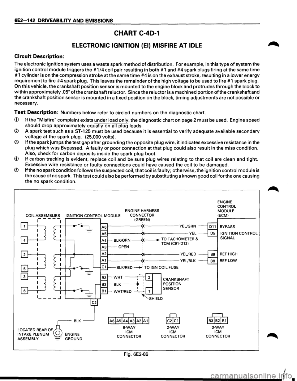
The electronic ignition system uses a waste spark method of distribution. For example, in this type of system the
ignition
control module triggers the #1 /4 coil pair resulting in both #1 and #4 spark plugs firing at the same time
# 1
cylinder is on the compression stroke at the same time #4 is on the exhaust stroke, resulting in a lower energy
requirement
to fire #4 spark plug. This leaves the remainder of the high voltage to be used to fire # 1 spark plug.
On this vehicle, the crankshaft position sensor is mounted to the engine block and protrudes through the block to
within approximately .05" ofthe crankshaft reluctor. Since the reluctor is a machined portion ofthe crankshaft and
the crankshaft position sensor is mounted in a fixed position on the
block, timing adjustments are not possible or
necessary.
Test Description: Numbers below refer to circled numbers on the diagnostic chart.
CD If the "Misfire" complaint exists under load only, the diagnostic chart on page 2 must be used. Engine speed
should drop approximately equally on all plug leads.
® A spark test such as a ST-125 must be used because it is essential to verify adequate available secondary
voltage at the spark plug. (25,000 volts).
@ If the spark jumps the test gap after grounding the opposite plug wire, it indicates excessive resistance in the
plug which was Bypassed. A faulty or poor connection at that plug could also result in the miss condition.
Also, check for carbon deposits inside the spark plug boot.
@ If carbon tracking is evident, replace coil and be sure plug wires relating to that coil are clean and tight.
Excessive
wire resistance or faulty connections could have caused the coil to be damaged.
@ If the no spark condition follows the suspected coil, that coil is faulty; otherwise, the ignition control module is
the cause
of no spark. This test could also be performed by substituting a known good coil for the one causing
the no spark condition.
ENGINE HARNESS
COIL ASSEMBLIES IGNITION CONTROL MODULE CONNECTOR
1-- - - -(GREEN)
~ '--1-1 -+---,
I
:TI
:D
r---------~~----------YE~GRN
~--------~~-------------VEL ' BLKJORN -----4---+-TO TACHOMETER & •
TCM (C91-D12) OPEN ! ' r---------~~----------YE~RED
r-----------<1~----------YEL!BLK ' BLKJRED ___..,TO IGN COIL FUSE
IAsiAsl;rJIA21A 1!
6-WAY ICM
CONNECTOR
Fig. 6E2-89
CRANKSHAFT
POSITION
SENSOR
lc0§,1
2-WAY ICM
CONNECTOR ENGINE
CONTROL
MODULE
(ECM)
BYPASS IGNITION CONTROL
SIGNAL
REF HIGH
REF LOW
IB!IB2I~1I
3-WAY ICM CONNECTOR
Page 840 of 1928
6E2-144 DRIVEABILITY AND EMISSIONS
CHART C-40-2
ELECTRONIC IGNITION (EI) MISFIRE UNDER LOAD
Circuit Description:
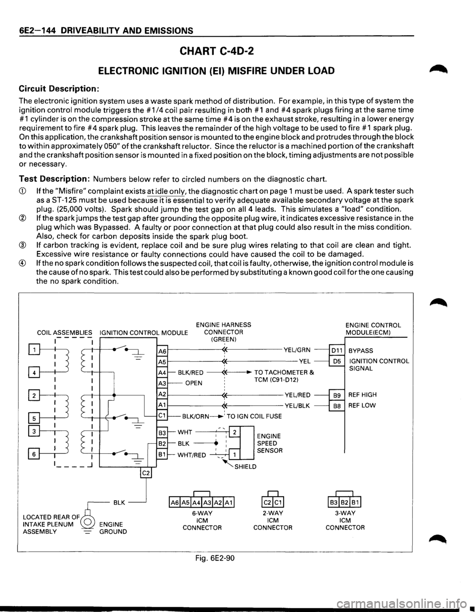
The electronic ignition system uses a waste spark method of distribution. For example, in this type of system the
ignition
control module triggers the # 1/4 coil pair resulting in both # 1 and #4 spark plugs firing at the same time
# 1 cylinder is on the compression stroke at the same time #4 is on the exhaust stroke, resulting in a lower energy
requirement
to fire #4 spark plug. This leaves the remainder of the high voltage to be used to fire #1 spark plug.
On this application, the crankshaft position sensor is mounted to the engine block and protrudes through the block
to within approximately 050" of the crankshaft reluctor. Since the reluctor is a machined portion of the crankshaft
and the crankshaft position sensor is mounted in a fixed position on the
block, timing adjustments are not possible
or necessary.
Test Description: Numbers below refer to circled numbers on the diagnostic chart.
CD If the "Misfire" complaint exists at idle only, the diagnostic chart on page 1 must be used. A spark tester such
as a ST-125 must be used because it is essential to verify adequate available secondary voltage at the spark
plug. (25,000 volts). Spark should jump the test gap on all 4 leads. This simulates a "load" condition.
® If the spark jumps the test gap after grounding the opposite plug wire, it indicates excessive resistance in the
plug which was Bypassed. A faulty or poor connection at that plug could also result in the miss condition.
Also, check for carbon deposits inside the spark plug boot.
® If carbon tracking is evident, replace coil and be sure plug wires relating to that coil are clean and tight.
Excessive
wire resistance or faulty connections could have caused the coil to be damaged.
® If the no spark condition follows the suspected coil, that coil is faulty, otherwise, the ignition control module is
the cause
of no spark. This test could also be performed by substituting a known good coil for the one causing
the no spark condition.
COIL ASSEMBLIES IGNITION CONTROL MODULE
ENGINE HARNESS
CONNECTOR
(GREEN) -----
:TI '--+I -l-----,
I
:TI
~
~--------~~-----------YE~GRN
~--------~~--------------VEL ' BLK/RED ------«--TO TACHOMETER &
OPEN ' TCM (C91-D12)
~--------~~-----------YE~RED
1------------((-----------YE~BLK ' BLK/ORN_.' TO IGN COIL FUSE
ENGINE SPEED
1 SENSOR
~SHIELD
IAsiAsii4ibiA21A11
6-WAY ICM
CONNECTOR
Fig. 6E2-90
lcik,l
2-WAY ICM
CONNECTOR ENGINE
CONTROL
MODULE(ECM)
BYPASS
IGNITION CONTROL
SIGNAL
REF HIGH
REF LOW
I
BJIB2I~1I
3-WAY ICM
CONNECTOR
•
Page 847 of 1928
DRIVEABILITY AND EMISSIONS 6E2-151
SECTION C-7
EXHAUST GAS RECIRCULATION (EGR) SYSTEM
CONTENTS
GENERAL DESCRIPTION ................. 6E2-151
Operation . . . . . . . . . . . . . . . . . . . . . . . . . . . 6E2-151
Exhaust Gas
Recirculation (EGR) Valve
Check . .
. . . . . . . . . . . . . . . . . . . . . . . . . . 6E2-152
Exhaust Gas
Recirculation (EGR)
Backpressure Transducer (BPT) Check 6E2-152
Exhaust Gas
Recirculation (EGR)
Vacuum Switch Valve (VSV) Solenoid
Check . .
. . . . . . . . . . . . . . . . . . . . . . . . . . 6E2-152
DIAGNOSIS ........................... 6E2-153
ON-VEHICLE SERVICE .................... 6E2-153
Exhaust Gas
Recirculation (EGR)
Manifold Passage ................... 6E2-153
Exhaust Gas
Recirculation (EGR)
Valve Replacement .................. 6E2-153
Exhaust
Gas Recirculation (EGR)
Backpressure Transducer (BPT)
Replacement ....................... 6E2-153
Exhaust Gas
Recirculation (EGR)
Vacuum Switch Valve (VSV) Replacement . 6E2-153
CHART C-7A Exhaust Gas
Recirculation (EGR)
System Check ...................... 6E2-154
GENERAL DESCRIPTION
The Exhaust Gas Recirculation (EGR) System controls
the formation of NOx (Oxides of Nitrogen) Emissions
by
recirculating the exhaust gases into the combustion
chamber. This is done through the intake
manifold.
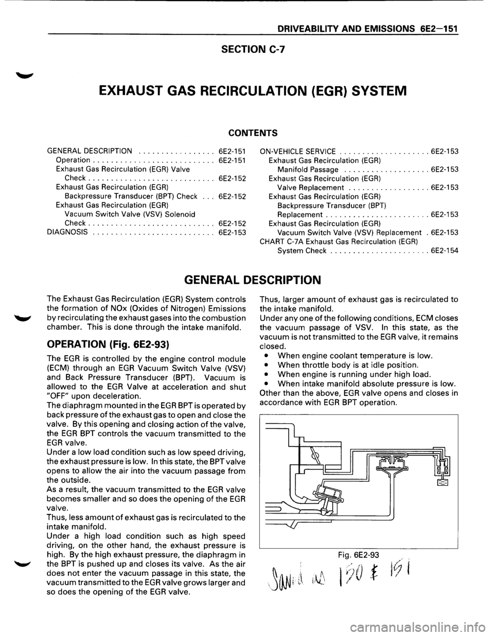
OPERATION (Fig. 6E2-93)
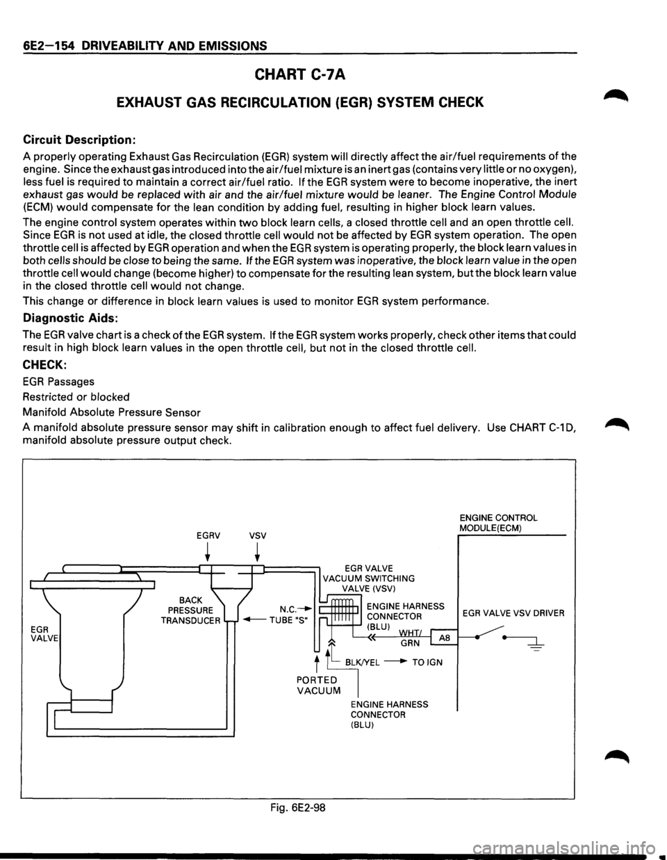
The EGR is controlled by the engine control module
(ECM) through an EGR Vacuum Switch Valve (VSV)
and Back Pressure Transducer (BPT). Vacuum is
allowed to the EGR Valve at acceleration and shut
"OFF" upon deceleration.
The diaphragm mounted in the EGR BPT is operated by
back pressure
of the exhaust gas to open and close the
valve. By this opening and closing action of the valve,
the EGR BPT controls the vacuum transmitted to the
EGR valve.
Under
a low load condition such as low speed driving,
the exhaust pressure is
low. In this state, the BPTvalve
opens to allow the air into the vacuum passage from
the outside.
As a
result, the vacuum transmitted to the EGR valve
becomes smaller and so does the opening of the EGR
valve.
Thus, less amount of exhaust gas is recirculated to the
intake
manifold.
Under
a high load condition such as high speed
driving, on the
other hand, the exhaust pressure is
high. By the high exhaust pressure, the diaphragm in
the
BPT is pushed up and closes its valve. As the air
does
not enter the vacuum passage in this state, the
vacuum transmitted
to the EGR valve grows larger and
so does the opening
of the EGR valve.
Thus, larger amount of exhaust gas is recirculated to
the intake manifold.
Under
any one ofthe following conditions, ECM closes
the vacuum passage of VSV. In this state, as the
vacuum is not transmitted
to the EGR valve, it remains
closed.
•
When engine coolant temperature is low.
•
When throttle body is at idle position.
• When engine is running under high load.
•
When intake manifold absolute pressure is low.
Other
than the above, EGR valve opens and closes in
accordance
with EGR BPT operation.
Fig. 6E2-93
i
.
,::·)I)' t
/
..f-l
Page 850 of 1928
6E2-154 DRIVEABILITY AND EMISSIONS
CHART C-7A
EXHAUST GAS RECIRCULATION (EGR) SYSTEM CHECK
Circuit Description:
A properly operating Exhaust Gas Recirculation (EGR) system will directly affect the air/fuel requirements of the
engine. Since the exhaust gas introduced into the air/fuel mixture is
an inert gas (contains very little or no oxygen),
less fuel is required
to maintain a correct air/fuel ratio. If the EGR system were to become inoperative, the inert
exhaust gas
would be replaced with air and the air/fuel mixture would be leaner. The Engine Control Module
(ECM) would compensate for the lean condition by adding fuel, resulting in higher block learn values.
The engine control system operates within
two block learn cells, a closed throttle cell and an open throttle cell.
Since EGR is not used at idle, the closed throttle cell would not be affected by EGR system operation. The open
throttle
cell is affected by EGR operation and when the EGR system is operating properly, the block learn values in
both
cells should be close to being the same. If the EGR system was inoperative, the block learn value in the open
throttle
cell would change (become higher) to compensate for the resulting lean system, but the block learn value
in the closed throttle
cell would not change.
This change or difference in block learn values is used to monitor
EGR system performance.
Diagnostic Aids:
The EGR valve chart is a check of the EGR system. If the EGR system works properly, check other items that could
result in high block learn values in the open throttle
cell, but not in the closed throttle cell.
CHECK:
EGR Passages
Restricted
or blocked
Manifold Absolute Pressure Sensor
A manifold absolute pressure sensor may shift in calibration enough to affect fuel delivery. Use CHART
C-1 0,
manifold absolute pressure output check.
EGR VALVE
EGRV
+
BACK
PRESSURE
TRANSDUCER
vsv
+ EGRVALVE VACUUM SWITCHING
VALVE (VSV)
ENGINE HARNESS
CONNECTOR
'+--+-' ( BLU)
GRN AB
t tt BL~L ---+ TO IGN
PORTED VACUUM
Fig. 6E2-98
ENGINE HARNESS
CONNECTOR
(BLU)
ENGINE CONTROL
MODULE(ECM)
EGR VALVE VSV DRIVER
•
Page 857 of 1928
DRIVEABILITV AND EMISSIONS 6E2-161
SECTION C-1 0
AIR CONDITIONING (A/C) COMPRESSOR CLUTCH CONTROL
SYSTEM
CONTENTS
General Description ..................... 6E2-161 On-Vehicle Service ...................... 6E2-161
Operation ........................... 6E2-161 Chart C-10 Air Conditioning (A/C) System
Diagnosis ............................. 6E2-161 Functional Check ...................... 6E2-162
GENERAL DESCRIPTION
OPERATION
This system consists of a high pressure cut-out switch,
Air Conditioning (A/C) compressor
relay, A/C thermo
switch relay, A/C controller and the compressor.
The high pressure cut-out switch
(normally closed),
opens when the head pressure gets too high. This will
disable
the A/C clutch, before damage can occur to the
compressor or other
A/C components.
When
A/C control switch is "ON" and the high pressure
switch and thermo switch are
closed, a request signal
is sent to the Engine Control Module (ECM). The ECM
will then energize the A/C clutch through the A/C
clutch relay. The A/C controller which is separate from
the ECM will then turn the A/C cooling fan "ON".
The A/C controller controls the A/C cooling fan, as well
as sending a signal to the ECM on model equipped with
automatic transmission.
The
ECM will disable the A/C clutch during Wide Open
Throttle,
or high power steering loads. The ECM has a
slight delay for clutch engagement to allow for the idle
to slightly increase. Refer to CHART C-1 0 for wiring and
circuit description.
DIAGNOSIS
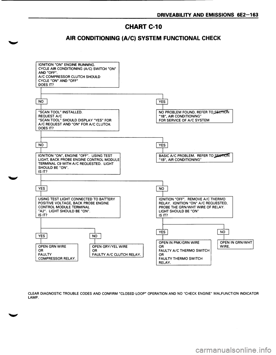
Chart C-10 should be used for the electrical portion of
the A/C circuit. Section 1 B should be used for
diagnosing the refrigerant portion of the system. The
"Scan tool" will be used in diagnosing the system, as it
has the ability to read the A/C request inputto the ECM,
as well as displaying when the ECM has commanded
the
A/C clutch "ON".
ON-VEHICLE SERVICE
For removal and replacement of A/C components,
refer to
A/C (SECTION 1 B) in this Manual.
Page 858 of 1928
6E2-162 DRIVEABILITY AND EMISSIONS
CHART C-10
AIR CONDITIONING (A/C) SYSTEM FUNCTIONAL CHECK
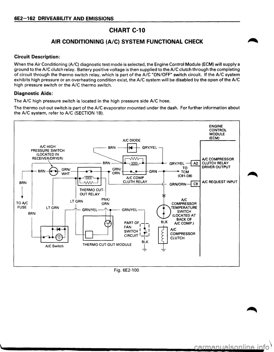
Circuit Description:
When the Air Conditioning (A/C) diagnostic test mode is selected, the Engine Control Module (ECM) will supply a
ground to the
A/C clutch relay. Battery positive voltage is then supplied to the A/C clutch through the completing
of circuit through the thermo switch relay, which is part of the A/C "ON/OFF" switch circuit. If the A/C system
exhibits high pressure or
an overheating condition exist, the A/C system will be disabled by the open of the A/C
high pressure switch or the A/C thermo switch.
Diagnostic Aids:
The A/C high pressure switch is located in the high pressure side A/C hose.
The
thermo cut-out switch is part of the A/C evaporator mounted under the dash. For further information about
the
A/C system, refer to A/C (SECTION 1 8).
BRN
TONC FUSE
NC HIGH
PRESSURE SWITCH
(LOCATED IN
RECEIVER/DRYER)
LTGRN
BRN
NC Switch
NC DIODE
BRN a GRY!YEL
THERMO CUTOUT RELAY
LTGRN PNK/ GRN
NCCOMP CLUTH RELAY
PARTOF1-FAN I SWITCH I I CIRCUIT I __ I
BLK THERMO CUT-OUT MODULE j_
Fig. 6E2-100
ENGINE
CONTROL
MODULE (ECM)
NC COMPRESSOR CLUTCH RELAY DRIVER OUTPUT
NC REQUEST INPUT
Page 859 of 1928
DRIVEABILITV AND EMISSIONS 6E2-163
CHART C-10
AIR CONDITIONING (A/C) SYSTEM FUNCTIONAL CHECK
IGNITION "ON" ENGINE RUNNING.
CYCLE AIR CONDITIONING (A/C) SWITCH "ON" AND "OFF". A/C COMPRESSOR CLUTCH SHOULD
CYCLE "ON" AND "OFF"
DOES IT?
$
$
"SCAN TOOL" INSTALLED.
NO PROBLEM FOUND, REFER TO)>e€TIO'N REQUEST A/C "1B", AIR CONDITIONING"
"SCAN TOOL" SHOULD DISPLAY "YES" FOR FOR SERVICE OF A/C SYSTEM A/C REQUEST AND "ON" FOR A/C CLUTCH.
DOES IT?
$
$
IGNITION "ON", ENGINE "OFF". USING TEST BASIC A/C PROBLEM. REFER TO~ LIGHT, BACK PROBE ENGINE CONTROL MODULE "1B", AIR CONDITIONING"
TERMINAL C9 WITH A/C REQUESTED. LIGHT
SHOULD BE "ON". IS IT?
$ $
USING TEST LIGHT CONNECTED TO BATTERY IGNITION "OFF". REMOVE A/C THERMO
POSITIVE VOLTAGE, BACK PROBE ENGINE RELAY. IGNITION "ON" A/C REQUESTED, CONTROL MODULE TERMINAL PROBE THE GRN/WHT WIRE OF RELAY. "A2". LIGHT SHOULD BE "ON". LIGHT SHOULD BE "ON" IS IT?
IS IT?
I
$ $
~ $ OPEN IN PNK/GRN WIRE I OPEN IN GRN/WHTJ OPEN GRN WIRE
OPEN GRY/YEL WIRE OR WIRE. OR OR FAULTY A/C THERMO SWITCH FAULTY FAULTY A/C CLUTCH RELAY. OR COMPRESSOR RELAY. FAULTY THERMO SWITCH RELAY.
CLEAR DIAGNOSTIC TROUBLE CODES AND CONFIRM "CLOSED LOOP" OPERATION AND NO "CHECK ENGINE" MALFUNCTION INDICATOR LAMP.
Page 860 of 1928
6E2 164 DRIVEABILITY AND EMISSIONS
SECTION C-13
POSITIVE CRANKCASE VENTILATION (PCV)
CONTENTS
GENERAL DESCRIPTION ................. 6E2-164 DIAGNOSIS ............................ 6E2-165
PCVValve .......................... 6E2-164 Functional Check of PCV ................ 6E2-165
Results of Incorrect Operation ............ 6E2-165
ON-VEHICLE SERVICE .................... 6E2-165
GENERAL DESCRIPTION
PCV VALVE
A Positive Crankcase Ventilation (PCV) system is used
to consume crankcase vapors in the combustion
process instead
of venting to atmosphere. Fresh air
from the throttle body is supplied to the crankcase,
mixed
with blow-by gases and then passed through a
Positive Crankcase Ventilation (PCV) into the intake
manifold.
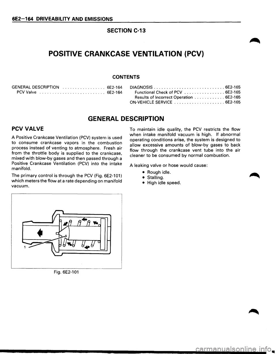
The primary control is through the PCV (Fig. 6E2-101)
which meters the
flow at a rate depending on manifold
vacuum.
Fig.
6E2-101
To maintain idle quality, the PCV restricts the flow
when intake manifold vacuum is high. If abnormal
operating conditions arise, the system is designed to
allow excessive amounts of blow-by gases to back
flow through the crankcase vent tube into the air
cleaner to be consumed by normal combustion.
A
leaking valve or hose would cause:
• Rough idle.
• Stalling.
•
High idle speed.
..
Page 874 of 1928
7A-2 AUTOMATIC TRANSMISSION (4L30-E)
Valve Body Assembly (Adapter Case) ....... 7A-168 Third Clutch and Sprag Unit ....................... 7A-195
Transmission Control
Module (TCM) ......... 7A-169 Third Clutch .................................................. 7A-196
Speed Sensor (Extension Housing) ............ 7A-169 Sprag
Unit ....................................................
7A-198
Transmission
Oil Temperature Sensor Second
Clutch .............................................. 7A-199
(Adapter Case) ..........................................
7A-170 3-4 Accumulator Piston ............................... 7A-200
Front Oil Seal (Converter Housing) ............ 7A-170 Reverse Clutch Piston and Center
Rear
Oil Seal (Extension Housing) ............. 7A-171 Support ..................................................... 7 A-202
Unit Repair ........................................................ 7A-173 Overrun Clutch and Turbine Shaft ............. 7A-204
Transmission (4L30-E) ................................. 7A-173 Main Data and Specifications ......................... 7 A-207
Converter Housing and Oil Pump General
Specifications ................................. 7 A-207
Assembly .................................................. 7 A-189 Torque
Specifications .................................. 7A-208
Oil
Pump ....................................................... 7A-190 Special Tools .................................................... 7A-211
Main Case Valve Body ................................. 7A-191 4L30-E Parts List.. ............................................. 7A-213
Adapter Case Valve Body ............................ 7A-193 Hydraulic
Circuit Diagram .......... End of This Manual
GENERAL DESCRIPTION
The 4L30-E is a 4-speed fully-automatic transmission.
It uses a microcomputer as a control unit to judge
running conditions
including throttle opening rate
and vehicle speed, then
it sets the shifting point in
the
optimum timing so that best driving performance
can be achieved.
In addition, the built-in shift mode select function can
select three shift modes according to the driver's
preference.
• Normal mode-Normal shift pattern.
• Winter mode-Starts in 3rd gear to reduce
slippage on ice
or snow.
• Power mode has a delayed upshift for when
more powerful acceleration is required.
Also, the built-in fail-safe
function ("backup mode")
assures driving performance even if the vehicle
speed sensor,
throttle signal or any solenoid fails.
Further, the self-diagnostic
function conducts diag
nosis in a short time when the control system fails,
thus improving serviceability.
The major features of 4L30-E are as follows:
• A compact structure consisting of 2 sets of
planetary gears and flat torque converter.
• Electronic control selects the optimum shift
mode according
to the driving conditions.
• Electronic control maintains the optimum hy
draulic pressure for clutch, band brake as well as
transmission so that shift feeling is improved.
• Two sets of planetary gears reduce friction of
power train.
Also, a lock-up mechanism in the torque con
verter reduces fuel consumption.
• Wide gear ratio and high torque rate of torque
converter provide
excellent starting perform
ance.
MODEL YEAR 1994-95 CHANGES
The Transmission Control Module (TCM) for ISUZU
TROOPER
models equipped with 4L30-E is changed
from "BOSCH" to "DELCO ELECTRONICS"
manufacture.
The main differences
which will be encountered
while servicing concerned vehicles are as follows:
Diagnostic Trouble Codes (DTC):
DTC's are changed: For example, DTC for
transmission gear error will be as follows depending
on the TCM unit:
-
On the "DELCO" unit (1994-95) ......... DTC 61
-On the "BOSCH" unit (1993-prior) ..... DTC 41
TCM Pin Connector:
The pin connector is changed. Therefore the
connections
to be made for troubleshooting also
change.
Shift Alteration when TECH 1 Tool is connected
toTCM:
SHIFTS WILL BE HARSH WHEN TECH 1 IS
CONNECTED.
Connection of TECH 1 automatically forces maximum
line pressure during shifts only.
Normal line pressure checks at idle and stall spe
can be carried out.
/
/
I J I
/
l
•