air condition ISUZU TROOPER 1995 Workshop Manual
[x] Cancel search | Manufacturer: ISUZU, Model Year: 1995, Model line: TROOPER, Model: ISUZU TROOPER 1995Pages: 1928
Page 729 of 1928
DRIVEABILITY AND EMISSIONS 6E2-33
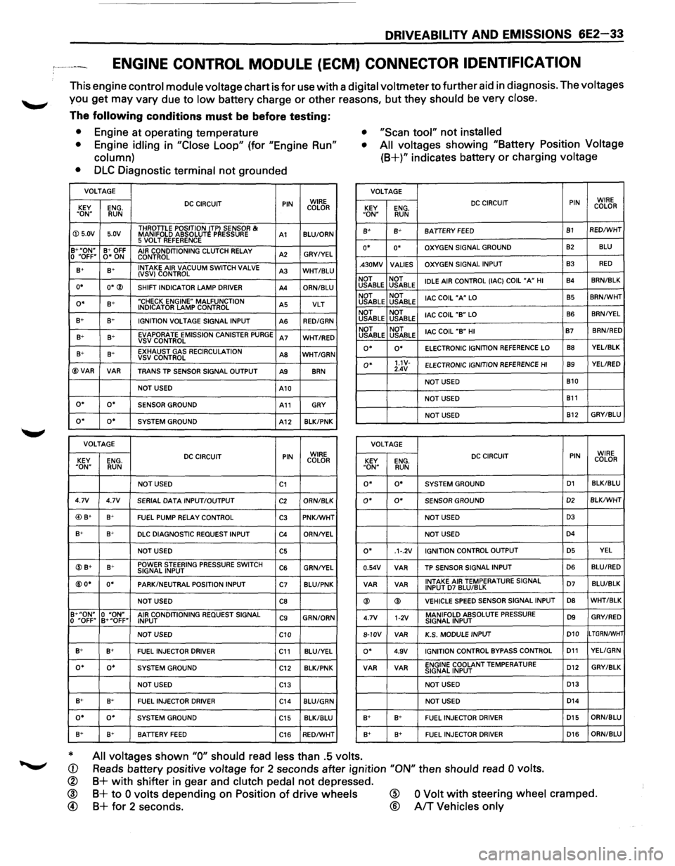
ENGINE CONTROL MODULE (ECM) CONNECTOR IDENTIFICATION
This engine control module voltage chart is for use with a digital voltmeter to further aid in diagnosis. The voltages
you get may vary due to low battery charge or other reasons, but they should be very close.
The following conditions must be before testing:
• Engine at operating temperature • "Scan tool" not installed
•
Engine idling in "Close Loop" (for "Engine Run"
column) •
All voltages showing "Battery Position Voltage
(8+)" indicates battery or charging voltage
•
DLC Diagnostic terminal not grounded
VOLTAGE VOLTAGE
DC CIRCUIT PIN WIRE
KEY ENG. COLOR
"ON" RUN
DC CIRCUIT PIN WIRE
KEY ENG. COLOR "ON" RUN
ID 5.0V 5.0V THROTILE
POSITION ~TP~ SENSOR & MANIFOLD ABSOLUT P ESSURE A1 BLU/ORN 8+ B+ BATIERY FEED B1 RED/WHT
5 VOLT REFERENCE B+"ON" B+ OFF AIR CONDITIONING CLUTCH RELAY A2 GRY/YEL 0 "OFF" 0* ON
CONTROL o• o• OXYGEN SIGNAL GROUND 82 BLU
B+ s+ INTAKE
AIR VACUUM SWITCH VALVE A3 WHT/BLU (VSV) CONTROL
o• O*® SHIFT INDICATOR LAMP DRIVER A4 ORN/BLU .430MV
VALlES OXYGEN
SIGNAL INPUT
B3 RED
NOT NOT
IDLE AIR CONTROL (lAC) COIL "A" HI B4 8RN/BLK USABLE
USABLE
o• B+ "CHECK ENGINE" MALFUNCTION A5 VLT INDICATOR LAMP CONTROL
B+ B+ IGNITION VOLTAGE SIGNAL INPUT
AS RED/GRN
NOT NOT
lAC COIL "A" LO B5 8RN/WHT USABLE USABLE
NOT NOT
lAC COIL
"B" LO B6 BRN/YEL USABLE
USABLE
B+ B+ EVAPORATE EMISSION CANISTER PURGE A7 WHT/RED VSVCONTROL NOT
NOT
lAC COIL "B" HI B7 BRN/RED USABLE
USABLE
B+ 8~ EXHAUST GAS RECIRCULATION AS WHT/GRN VSV CONTROL
@VAR VAR TRANS TP SENSOR SIGNAL OUTPUT A9 8RN
o• o• ELECTRONIC IGNITION REFERENCE LO 88 YEL/BLK
o• 1.1V-ELECTRONIC
IGNITION REFERENCE HI B9 YEL/RED
2.4V
NOT USED B10
NOT USED
A10
NOT USED
B11 o• o• SENSOR GROUND A11 GRY
NOT USED B12 GRY/BLU o• o• SYSTEM
GROUND A12 8LK/PNK
VOLTAGE
VOLTAGE
DC CIRCUIT PIN WIRE
KEY ENG. COLOR DC CIRCUIT PIN WIRE
KEY ENG. COLOR "ON" RUN "ON" RUN
NOT USED C1 o• o• SYSTEM GROUND D1 BLK/BLU
4.7V 4.7V
SERIAL DATA INPUT/OUTPUT C2 ORN/8LK o• 0* SENSOR GROUND D2 BLK/WHT
@) B+ B+ FUEL PUMP RELAY CONTROL C3 PNK/WHT NOT USED D3
B+ B+ DLC DIAGNOSTIC REQUEST INPUT C4 ORN/YEL NOT USED D4
NOT USED C5 o• .1·.2V IGNITION
CONTROL OUTPUT D5 YEL
@B+ B+ POWER STEERING PRESSURE SWITCH C6 GRN/YEL SIGNAL INPUT 0.54V VAR
TP SENSOR
SIGNAL INPUT D6 BLU/RED
@O* o• PARK/NEUTRAL POSITION
INPUT C7 BLU/PNK VAR
VAR INTAKE AIR TEMPERATURE SIGNAL D7 BLU/BLK INPUT D7 BLU/BLK
NOT USED CB ® ® VEHICLE SPEED SENSOR
SIGNAL INPUT D8 WHT/BLK
B+"ON" 0 "ON" AIR CONDITIONING REQUEST SIGNAL C9 GRN/ORN
0 "OFF" B+"OFF"
INPUT 4.7V 1-2V MANIFOLD ABSOLUTE PRESSURE D9 GRY/RED SIGNAL
INPUT
NOT USED
C10 8-10V
VAR K.S.
MODULE INPUT D10 LTGRN/WHT
B+ B+ FUEL INJECTOR
DRIVER C11 BLU/YEL o• 4.9V IGNITION CONTROL BYPASS CONTROL D11 YELIGRN
o• o• SYSTEM GROUND
C12 BLK/PNK VAR VAR ENGINE COOLANT TEMPERATURE
D12 GRY/BLK SIGNAL
INPUT
NOT USED
C13 NOT USED D13
B+ 8+
FUEL INJECTOR DRIVER C14 BLU/GRN NOT USED D14
o• o• SYSTEM GROUND
C15 BLK/BLU B+ B+ FUEL INJECTOR DRIVER D15 ORN/BLU
8+ B+ BATIERY FEED C16 RED/WHT B+ 8+
FUEL INJECTOR DRIVER D16 ORN/8LU
* All voltages shown "0" should read less than .5 volts.
Reads battery positive voltage for 2 seconds after ignition "ON" then should read 0 volts. CD
®
® @
B+ with shifter in gear and clutch pedal not depressed.
B+ to 0 volts depending on Position of drive wheels
B+ for 2 seconds.
@
®
0 Volt with steering wheel cramped.
A/T Vehicles only
Page 730 of 1928
6E2-34 DRIVEABILITY AND EMISSIONS
''SCAN TOOL" ON-BOARD DIAGNOSTIC (OBD) SYSTEM CHECK
The Diagnostic Circuit is an organized approach to identifying a problem created by an electronic engine control
system malfunction. It must be the starting point for any drive ability complaint diagnosis, because it directs the
service technician to the next
logical step in diagnosing the complaint.
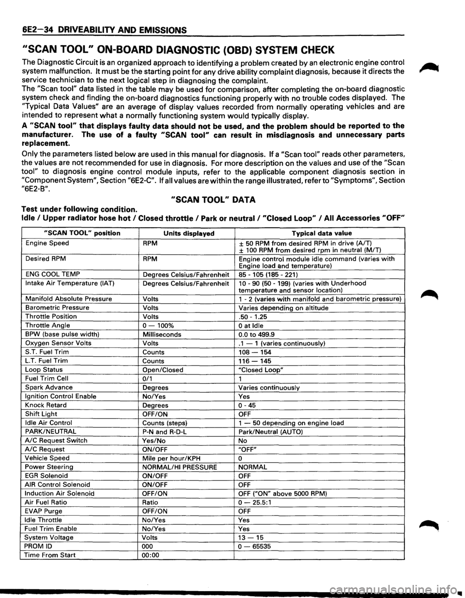
The "Scan tool" data listed in the table may be used for comparison, after completing the on-board diagnostic
system check and finding the on-board diagnostics functioning
properly with no trouble codes displayed. The
"Typical Data Values" are an average of display values recorded from normally operating vehicles and are
intended
to represent what a normally functioning system would typically display.
A "SCAN tool" that displays faulty data should not be used, and the problem should be reported to the
manufacturer. The use of a faulty "SCAN tool" can result in misdiagnosis and unnecessary parts
replacement.
Only the parameters listed below are used in this manual for diagnosis. If a "Scan tool" reads other parameters,
the
values are not recommended for use in diagnosis. For more description on the values and use of the "Scan
tool" to diagnosis engine control module inputs, refer to the applicable component diagnosis section in
"Component System", Section "6E2-C". If all values are within the range illustrated, refer to "Symptoms", Section
"6E2-B".
"SCAN TOOL" DATA
Test under following condition.
Idle I Upper radiator hose hot I Closed throttle I Park or neutral I "Closed Loop" I All Accessories "OFF"
"SCAN TOOL" position Units displayed Typical data value
Engine Speed RPM ± 50 RPM from desired RPM in drive (A/T) ± 100 RPM from desired rpm in neutral (MIT)
Desired
RPM RPM Engine control module idle command (varies with Engine load and temperature)
ENG COOL TEMP
Degrees Celsius/Fahrenheit 85-105 (185-221)
Intake Air Temperature (IAT) Degrees Celsius/Fahrenheit 10-90 (50-199) (varies with Underhood
temperature and sensor location)
Manifold Absolute Pressure Volts 1 - 2 (varies with manifold and barometric pressure)
Barometric Pressure Volts Varies depending on altitude
Throttle Position Volts .50-1.25
Throttle Angle 0-100% 0 at Idle
BPW (base pulse width) Milliseconds 0.0 to 499.9
Oxygen Sensor Volts Volts .1 - 1 (varies continuously)
S.T. Fuel
Trim Counts 108-154
LT. Fuel Trim Counts 116-145
Loop Status
Open/Closed "Closed Loop"
Fuel Trim Cell 0/1 1
Spark Advance Degrees Varies continuously
Ignition Control Enable No/Yes Yes
Knock Retard
Degrees
0-45
Shift Light OFF/ON OFF
Idle Air Control
Counts (steps) 1 -50 depending on engine load
PARK/NEUTRAL P-N and R-D-L Park/Neutral (AUTO)
A/C Request Switch Yes/No No
A/C Request ON/OFF "OFF"
Vehicle Speed
Mile per hour/KPH 0
Power Steering
NORMAL/HI PRESSURE NORMAL
EGR Solenoid
ON/OFF OFF
AIR Control Solenoid
ON/OFF OFF
Induction Air Solenoid OFF/ON OFF ("ON" above 5000 RPM)
Air Fuel Ratio Ratio 0-25.5:1
EVAP Purge OFF/ON OFF
Idle Throttle No/Yes Yes
Fuel Trim Enable No/Yes Yes
System Voltage Volts 13-15
PROM ID 000 0-65535
Time From Start 00:00
Page 756 of 1928
6E2-60 DRIVEABILITY AND EMISSIONS
DIAGNOSTIC TROUBLE CODE (DTC) 14A
ENGINE COOLANT TEMPERATURE (ECT) SENSOR CIRCUIT
(HIGH
TEMPERATURE INDICATED)
Circuit Description:
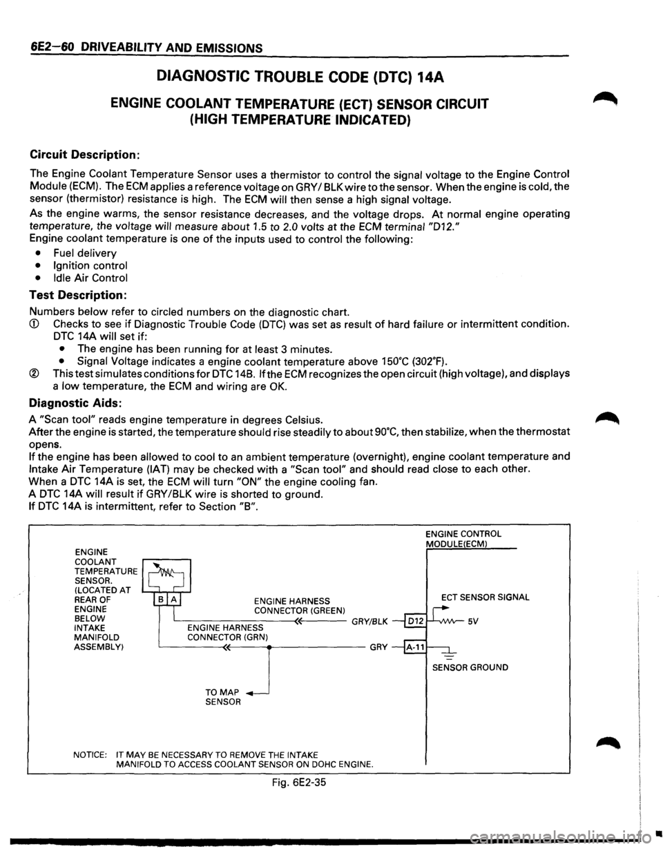
The Engine Coolant Temperature Sensor uses a thermistor to control the signal voltage to the Engine Control
Module
(ECM). The ECM applies a reference voltage on GRY I 8LK wire to the sensor. When the engine is cold, the
sensor (thermistor) resistance is high. The
ECM will then sense a high signal voltage.
As the engine warms, the sensor resistance decreases, and the voltage drops. At normal engine operating
temperature, the
voltage will measure about 1.5 to 2.0 volts at the ECM terminal "D12."
Engine coolant temperature is one of the inputs used to control the following:
• Fuel delivery
• Ignition control
• Idle
Air Control
Test Description:
Numbers below refer to circled numbers on the diagnostic chart.
CD Checks to see if Diagnostic Trouble Code (DTC) was set as result of hard failure or intermittent condition.
DTC 14A will set if:
• The engine has been running for at least 3 minutes.
• Signal Voltage indicates a engine coolant temperature above 15o•c (302.F).
® This test simulates conditions for DTC 148. lfthe ECM recognizes the open circuit (high voltage), and displays
a low temperature, the ECM and wiring are OK.
Diagnostic Aids:
A "Scan tool" reads engine temperature in degrees Celsius.
After the engine is started, the temperature should rise steadily to about so·c, then stabilize, when the thermostat
opens.
If the engine has been allowed to cool to an ambient temperature (overnight), engine coolant temperature and
Intake Air Temperature (IAT) may be checked with a "Scan tool" and should read close to each other.
When a
DTC 14A is set, the ECM will turn "ON" the engine cooling fan.
A
DTC 14A will result if GRY /8LK wire is shorted to ground.
If DTC 14A is intermittent, refer to Section "8".
ENGINE
COOLANT
TEMPERATURE SENSOR. (LOCATED AT REAR OF ENGINE
BELOW
INTAKE
MANIFOLD
ASSEMBLY) ENGINE
HARNESS CONNECTOR(GREEN) L----------<~---GRY/BLK ENGINE HARNESS
CONNECTOR (GRN)
L__ ___ T_O~M(~A-P-~-~-------GRY
SENSOR
NOTICE: IT
MAY BE NECESSARY TO REMOVE THE INTAKE
MANIFOLD TO ACCESS COOLANT SENSOR ON DOHC ENGINE.
Fig. 6E2-35
ENGINE CONTROL MODULE(ECM)
ECT SENSOR SIGNAL
SENSOR GROUND
•
Page 758 of 1928
6E2~62 DRIVEABILITY AND EMISSIONS
DIAGNOSTIC TROUBLE CODE (DTC) 148
ENGINE COOLANT TEMPERATURE (ECT) SENSOR CIRCUIT
(LOW TEMPERATURE INDICATED)
Circuit Description:
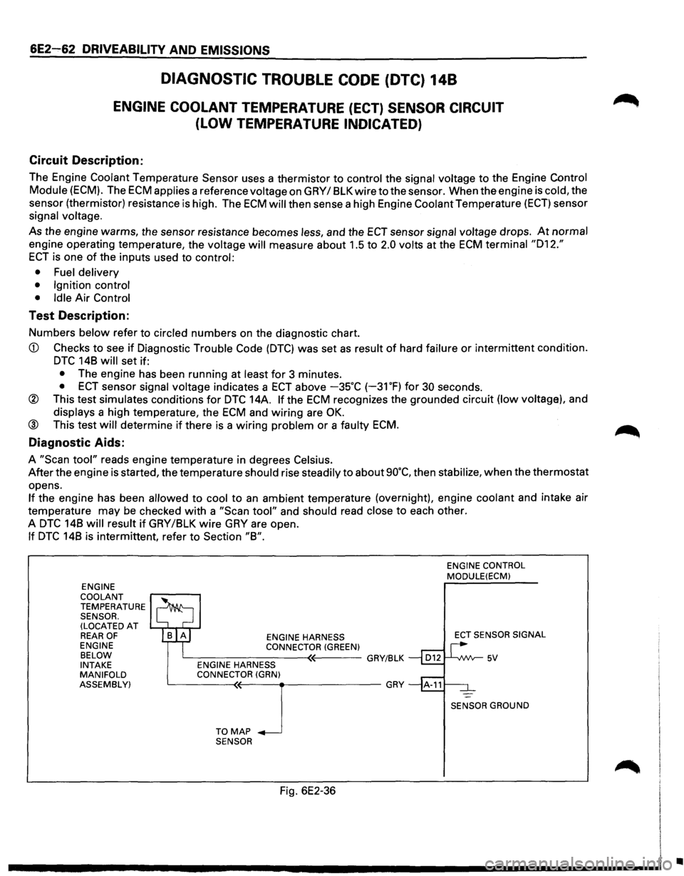
The Engine Coolant Temperature Sensor uses a thermistor to control the signal voltage to the Engine Control
Module (ECM). The ECM applies a reference voltage on GRY I 8LK wire to the sensor. When the engine is cold, the
sensor (thermistor) resistance
is high. The ECM will then sense a high Engine Coolant Temperature (ECT) sensor
signal
voltage.
As the engine warms, the sensor resistance becomes less, and the ECT sensor signal voltage drops. At normal
engine operating temperature, the voltage will measure about 1.5 to 2.0 volts at the ECM terminal "012."
ECT is one of the inputs used to control:
• Fuel delivery
• Ignition control
• Idle
Air Control
Test Description:
Numbers below refer to circled numbers on the diagnostic chart.
CD Checks to see if Diagnostic Trouble Code (DTC) was set as result of hard failure or intermittent condition.
DTC 148 will set if:
• The engine has been running at least for 3 minutes.
• ECT sensor signal voltage indicates a ECT above -35°C (-31 OF) for 30 seconds.
® This test simulates conditions for DTC 14A. If the ECM recognizes the grounded circuit (low voltage), and
displays a high temperature, the ECM and wiring are OK.
@ This test will determine if there is a wiring problem or a faulty ECM.
Diagnostic Aids:
A "Scan tool" reads engine temperature in degrees Celsius.
After the engine is started, the temperature should rise steadily to about 90°C, then stabilize, when the thermostat
opens.
If the engine has been allowed to cool to an ambient temperature (overnight), engine coolant and intake air
temperature may be checked
with a "Scan tool" and should read close to each other.
A
DTC 148 will result if GRY/8LK wire GRY are open.
If DTC 148 is intermittent, refer to Section "8".
ENGINE
COOLANT
TEMPERATURE SENSOR.
(LOCATED AT REAR OF ENGINE
BELOW
INTAKE
MANIFOLD
ASSEMBLY) ENGINE
HARNESS
CONNECTOR (GREEN) c__---------<~'----GRY/BLK ENGINE HARNESS
CONNECTOR (GRN)
~---T-0--<'M<(--A-P_J ___________ GRY
SENSOR
Fig. 6E2-36
ENGINE CONTROL MODULE(ECM)
ECT
SENSOR SIGNAL
SENSOR GROUND
•
Page 764 of 1928
6E2-68 DRIVEABILITV AND EMISSIONS
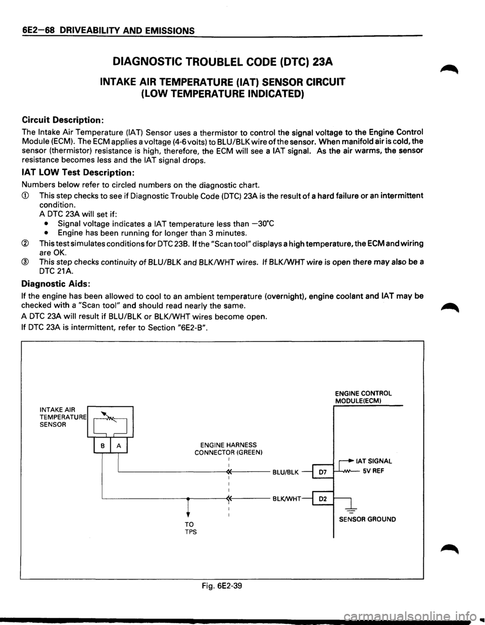
DIAGNOSTIC TROUBLEL CODE (DTC) 23A
INTAKE AIR TEMPERATURE {IAT) SENSOR CIRCUIT
(LOW TEMPERATURE INDICATED)
Circuit Description:
The Intake Air Temperature (IAT) Sensor uses a thermistor to control the signal voltage to the Engine Control
Module
(ECM). The ECM applies a voltage (4-6volts) to BLU/BLK wire of the sensor. When manifold air is cold, the
sensor (thermistor) resistance is high, therefore, the
ECM will see a IAT signal. As the air warms, the sensor
resistance becomes
less and the IAT signal drops.
IAT LOW Test Description:
Numbers below refer to circled numbers on the diagnostic chart.
CD This step checks to see if Diagnostic Trouble Code (DTC) 23A is the result of a hard failure or an intermittent
condition.
A
DTC 23A will set if:
• Signal voltage indicates a IAT temperature less than -30"C
• Engine has been running for longer than 3 minutes.
® This test simulates conditions for DTC 238. If the "Scan tool" displays a high temperature, the ECM and wiring
are OK.
@ This step checks continuity of BLU/BLK and BLK/WHT wires. If BLK/WHT wire is open there may also be a
DTC 21A.
Diagnostic Aids:
If the engine has been allowed to cool to an ambient temperature (overnight), engine coolant and IAT may be
checked
with a "Scan tool" and should read nearly the same. ~
A DTC 23A will result if BLU/BLK or BLK/WHT wires become open.
If DTC 23A is intermittent, refer to Section "6E2-B".
INTAKE AIR TEMPERATURE SENSOR
ENGINE HARNESS
CONNECTOR
(GREEN) I
L-----------«----BLU/BLK
TO TPS
Fig. 6E2-39
ENGINE CONTROL
MODULE(ECM)
IATSIGNAL
1--'--IW'--5V REF
SENSOR GROUND
Page 766 of 1928
6E2-70 DRIVEABILITV AND EMISSIONS
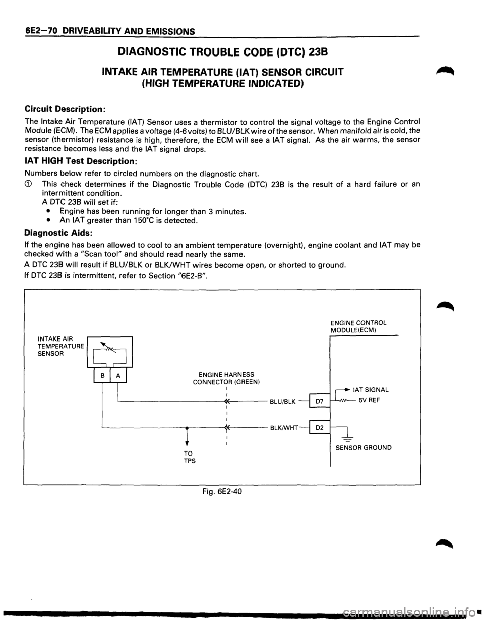
DIAGNOSTIC TROUBLE CODE (DTC) 238
INTAKE AIR TEMPERATURE (IAT) SENSOR CIRCUIT
(HIGH
TEMPERATURE INDICATED)
Circuit Description:
The Intake Air Temperature (IAT) Sensor uses a thermistor to control the signal voltage to the Engine Control
Module (ECM). The
ECM applies a voltage (4-6 volts) to 8LU/8LK wire ofthe sensor. When manifold air is cold, the
sensor (thermistor) resistance is high, therefore, the
ECM will see a IAT signal. As the air warms, the sensor
resistance becomes less and the
IAT signal drops.
IAT HIGH Test Description:
Numbers below refer to circled numbers on the diagnostic chart.
CD This check determines if the Diagnostic Trouble Code (DTC) 238 is the result of a hard failure or an
intermittent condition.
A
DTC 238 will set if:
• Engine has been running for longer than 3 minutes.
• An IAT greater than 150°C is detected.
Diagnostic Aids:
If the engine has been allowed to cool to an ambient temperature (overnight), engine coolant and IAT may be
checked with a "Scan tool" and should read nearly the same.
A
DTC 238 will result if 8LU/8LK or 8LK/WHT wires become open, or shorted to ground.
If DTC 238 is intermittent, refer to Section "6E2-8".
INTAKE AIR TEMPERATURE SENSOR
ENGINE
HARNESS CONNECTOR (GREEN) I
L-----------~;-----BLU/BLK
TO TPS
Fig. 6E2-40
ENGINE CONTROL MODULE(ECM)
IAT SIGNAL
1--J..-,JW--5V REF
SENSOR GROUND
II
Page 780 of 1928
6E2-84 DRIVEABILITY AND EMISSIONS
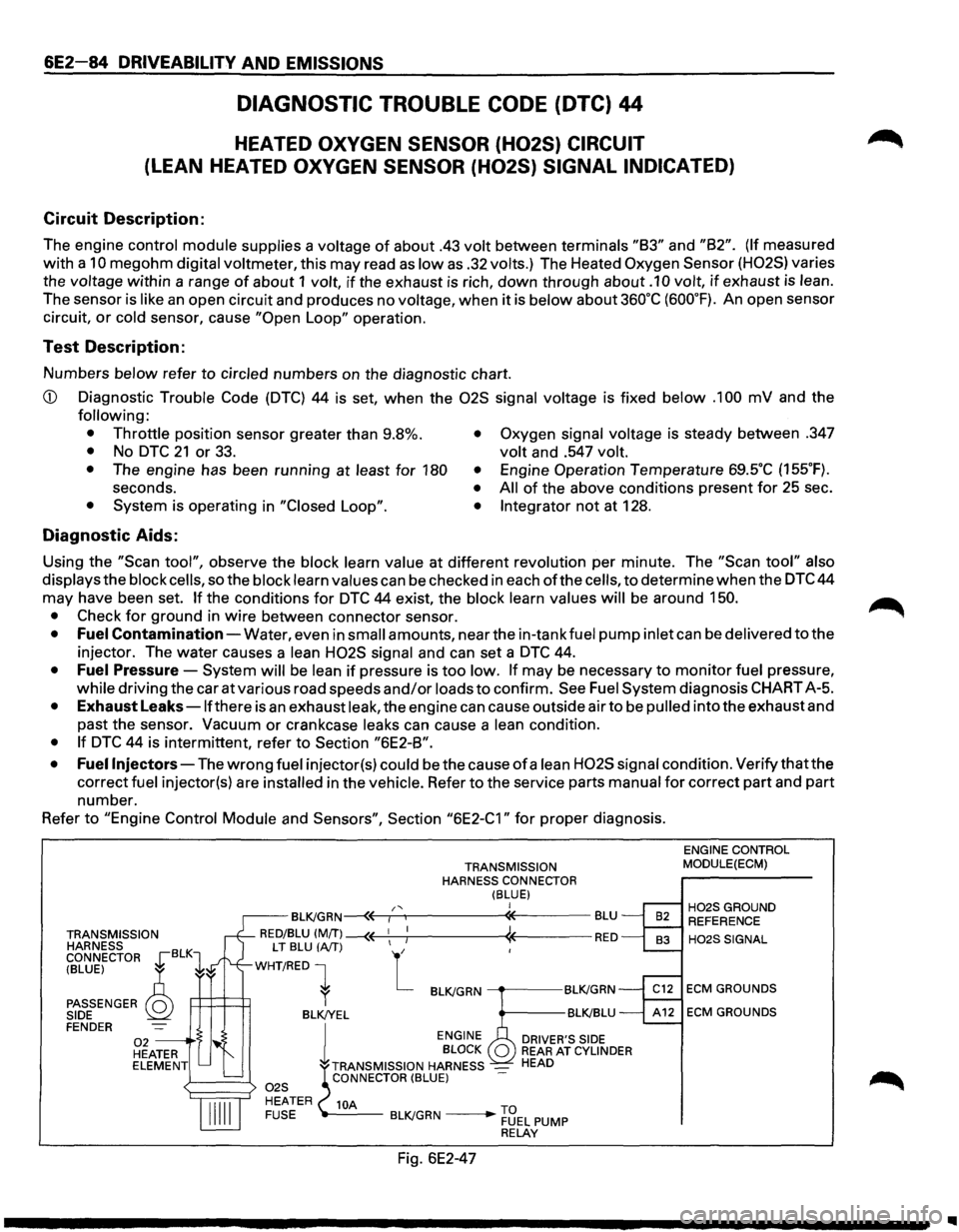
DIAGNOSTIC TROUBLE CODE (DTC) 44
HEATED OXYGEN SENSOR (H02S) CIRCUIT
(LEAN HEATED OXYGEN SENSOR (H02S) SIGNAL INDICATED)
Circuit Description:
The engine control module supplies a voltage of about .43 volt between terminals "83" and "82". (If measured
with a
10 megohm digital voltmeter, this may read as low as .32 volts.) The Heated Oxygen Sensor (H02S) varies
the
voltage within a range of about 1 volt, if the exhaust is rich, down through about .1 0 volt, if exhaust is lean.
The sensor is like an open circuit and produces no voltage, when it is below about 360°C (600°F). An open sensor
circuit,
or cold sensor, cause "Open Loop" operation.
Test Description:
Numbers below refer to circled numbers on the diagnostic chart.
CD Diagnostic Trouble Code (DTC) 44 is set, when the 02S signal voltage is fixed below .1 00 mV and the
following:
• Throttle
position sensor greater than 9.8%.
• No DTC 21 or 33. • Oxygen signal voltage is steady between .347
volt and .547 volt.
•
The engine has been running at least for 180 •
seconds. • • System is operating in "Closed Loop". •
Engine Operation Temperature 69SC (155°F).
All of the above conditions present for 25 sec .
Integrator not at 128 .
Diagnostic Aids:
Using the "Scan tool", observe the block learn value at different revolution per minute. The "Scan tool" also
displays
the block cells, so the block learn values can be checked in each ofthe cells, to determine when the DTC 44
may have been set.
If the conditions for DTC 44 exist, the block learn values will be around 150.
•
Check for ground in wire between connector sensor.
• Fuel Contamination-Water, even in small amounts, near the in-tank fuel pump inlet can be delivered to the
injector. The water causes a
lean H02S signal and can set a DTC 44.
• Fuel Pressure-System will be lean if pressure is too low. If may be necessary to monitor fuel pressure,
while driving the car at various road speeds and/or loads to confirm. See Fuel System diagnosis CHART A-5.
• Exhaust Leaks -lfthere is an exhaust leak, the engine can cause outside air to be pulled into the exhaust and
past the sensor.
Vacuum or crankcase leaks can cause a lean condition.
• If DTC 44 is intermittent, refer to Section "6E2-8".
• Fuel
Injectors-The wrong fuel injector(s) could be the cause of a lean H02S signal condition. Verify that the
correct
fuel injector(s) are installed in the vehicle. Refer to the service parts manual for correct part and part
number.
Refer
to "Engine Control Module and Sensors", Section "6E2-C1" for proper diagnosis.
TRANSMISSION
HARNESS
CONNECTOR
~BLK1
TRANSMISSION
HARNESS CONNECTOR
(BLUE) I /' BL~GRN~r-~----------~-------BLU
RED/BLU (MfT) --(( 1
1 ; « RED
(BLUE) ~
PASSENGER Q SIDE
LT BLU (A/T) L
WHT/RED 1
P:::l=t=t1 l BL~GRN ----.-----BL~GRN
BLK!YEL BL~BLU FENDER 02 --·S HEATER ELEMENT l
ENGINE
DRIVER'S SIDE BLOCK REAR AT CYLINDER
TRANSMISSION HARNESS _ HEAD CONNECTOR (BLUE)
10A -----BL~GRN ____ .,.... ~3EL PUMP RELAY
Fig. 6E2-47
ENGINE CONTROL
MODULE(ECM)
H02SGROUND REFERENCE
H02SSIGNAL
ECM GROUNDS
ECM GROUNDS
..
Page 786 of 1928
6E2-90 DRIVEABILITY AND EMISSIONS
INTERMITTENTS
Definition: Problem may or may not turn "ON" the
"Check Engine" malfunction indicator lamp or store
Diagnostic
Trouble Code (DTC).
DO NOT use the DTC charts in "Engine Components/
Wiring Diagrams/Diagnostic
Charts," Section "6E2-A"
for intermittent problem. The fault must be present to
locate the problem. If a fault is intermittent, use of DTC
charts may result in replacement of good parts.
•
• Most intermittent problems are caused by faulty
electrical
connections or wiring. Perform careful
visual/physical
check as described at start of
"Symptoms," Section "6E2-B." Check for:
Poor mating
of the connector halves. or
terminal not fully seated in the connector body
(backed out).
Improperly formed or damaged terminal. All
connector
terminals in the problem circuit
should be carefully reformed or replaced to
insure proper contact tension.
Poor
terminal to wire connection. This
requires removing the
terminal from the
connector body to check. Refer to
SECTION 8
"Wiring Harness Service,"
If a visual/physical check does not find the cause
of the problem, the car can be driven with a
voltmeter connected to a suspected circuit. A
"Scan tool" can also be used to help detect
intermittent conditions. An abnormal
voltage, or
"Scan" tool reading, when the problem occurs,
indicates the
problem may be in that circuit. If the wiring
and connectors check
OK, and a DTC was
stored
for a circuit having a sensor, except for
DTC(s) 44 and 45, substitute a known good sensor
and recheck.
• Loss of DTC memory. To check, disconnect
throttle position (TP) sensor and idle engine until
"Check
Engine" malfunction indicator lamp comes
"ON". DTC 21 should be stored, and kept in
memory when ignition is turned "OFF". If not, the
Engine
Control Module (ECM) is faulty.
•
An intermittent "Check Engine" malfunction
indicator
lamp with no stored DTC may be caused
by:
Ignition coil shorted to ground and arcing at
spark
plug wires or plugs.
"Check
Engine" malfunction indicator lamp
wire to ECM shorted to ground.
Diagnostic
"test" terminal wire to ECM,
shorted to ground.
ECM grounds, refer to ECM wiring diagrams.
• Check for an electrical system interference caused
by a defective
relay, ECM driven solenoid, or
switch. They can cause a sharp electrical surge.
Normally, the problem will occur when the faulty
component is operated.
• Check for improper installation of electrical
options such as lights, 2 way radios, etc.
• Ignition control wires should be routed away from
spark plug wires, electronic ignition (EI) wires, El
housing, coil and generator. Ground wire from
ECM to El should have a good connection.
• If problem has not been found, refer to "ECM
Connector Symptom" charts at the end of
"Symptoms," Section "6E2-B."
HARD START
Definition: Engine cranks OK, but does not start for a
long time. Does eventually run, or may
start
but immediately dies.
PRELIMINARY CHECKS
• Perform the careful visual/physical checks as
described at start of "Symptoms," Section "6E2-
B".
•
Make sure the driver is using the correct starting
procedure.
SENSORS
• CHECK: Engine coolant temperature sensor using
a
"Scan tool", compare engine coolant
temperature with ambient temperature
on
cold engine. -
If engine coolant temperature
readings
is 5 degrees greater than or less than
ambient air temperature on a
cold
engine, check resistance in engine
coolant temperature sensor circuit
or
sensor itself. Compare engine coolant
temperature sensor resistance value
to the "Diagnostic Aids" chart on
DTC
14 chart.
• CHECK: Manifold absolute pressure sensor.
Check for flooding and/or correct sensor
for vehicle.
• CHECK: TP sensor for binding or a high TP sensor
voltage with the throttle closed (should
read between 0.54 volt and 1.25 volts.)
Page 787 of 1928
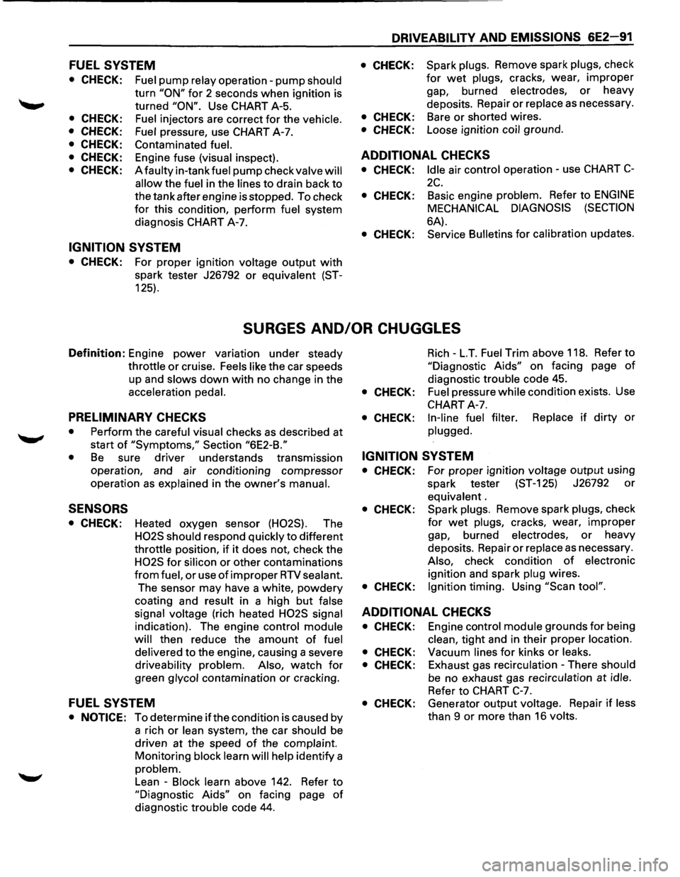
FUEL SYSTEM
• CHECK:
• CHECK:
• CHECK:
• CHECK:
• CHECK:
• CHECK:
Fuel pump relay operation-pump should
turn "ON" for 2 seconds when ignition is
turned
"ON". Use CHART A-5.
Fuel injectors are correct for the vehicle.
Fuel
pressure, use CHART A-7.
Contaminated
fuel.
Engine fuse (visual inspect).
A
faulty in-tank fuel pump check valve will
allow
the fuel in the lines to drain back to
the tank after engine is stopped. To check
for this condition, perform fuel system
diagnosis CHART A-7.
IGNITION SYSTEM
• CHECK: For proper ignition voltage output with
spark tester J26792 or equivalent (ST-
125).
DRIVEABILITY AND EMISSIONS 6E2-91
• CHECK: Spark plugs. Remove spark plugs, check
for wet plugs, cracks, wear, improper
gap, burned electrodes, or heavy
deposits. Repair
or replace as necessary.
• CHECK: Bare or shorted wires.
• CHECK: Loose ignition coil ground.
ADDITIONAL CHECKS
• CHECK: Idle air control operation-use CHART C-
2C.
• CHECK: Basic engine problem. Refer to ENGINE
MECHANICAL DIAGNOSIS (SECTION
6A).
• CHECK: Service Bulletins for calibration updates.
SURGES AND/OR CHUGGLES
Definition: Engine power variation under steady
throttle or cruise. Feels like the car speeds
up and
slows down with no change in the
acceleration pedal.
PRELIMINARY CHECKS
• Perform the careful visual checks as described at
start
of "Symptoms," Section "6E2-B."
•
Be sure driver understands transmission
operation, and air conditioning compressor
operation
as explained in the owner's manual.
SENSORS
• CHECK: Heated oxygen sensor (H02S). The
H02S should respond quickly to different
throttle position, if it does not, check the
H02S for silicon or other contaminations
from fuel, or use of improper RTV sealant.
The sensor may have a white, powdery
coating and result in a high but false
signal voltage
(rich heated H02S signal
indication). The engine control module
will
then reduce the amount of fuel
delivered
to the engine, causing a severe
driveability problem. Also, watch for
green glycol contamination or cracking.
FUEL SYSTEM
• NOTICE: To determine ifthe condition is caused by
a rich
or lean system, the car should be
driven at the speed of the complaint.
Monitoring block learn will help identify a
problem.
Lean -Block learn above 142. Refer to
"Diagnostic Aids" on facing page of
diagnostic trouble code 44.
Rich -L.T. Fuel Trim above 118. Refer to
"Diagnostic Aids" on facing page of
diagnostic trouble code 45.
• CHECK: Fuel pressure while condition exists. Use
CHART A-7.
• CHECK: In-line fuel filter. Replace if dirty or
plugged.
IGNITION SYSTEM
• CHECK: For proper ignition voltage output using
spark tester (ST-125) J26792
or
equivalent .
• CHECK: Spark plugs. Remove spark plugs, check
for wet plugs, cracks, wear, improper
gap, burned electrodes, or heavy
deposits. Repair
or replace as necessary.
Also, check condition of electronic
ignition and spark plug wires.
• CHECK: Ignition timing. Using "Scan tool".
ADDITIONAL CHECKS
• CHECK: Engine control module grounds for being
clean, tight and in their proper location.
• CHECK: Vacuum lines for kinks or leaks.
• CHECK: Exhaust gas recirculation -There should
be no exhaust gas recirculation at idle.
Refer to CHART C-7.
• CHECK: Generator output voltage. Repair if less
than 9 or more than 16 volts.
Page 788 of 1928
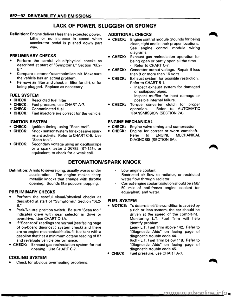
6E2-92 DRIVEABILITY AND EMISSIONS
LACK OF POWER, SLUGGISH OR SPONGY
Definition: Engine delivers less than expected power.
Little or no increase in speed when
accelerator
pedal is pushed down part
way.
PRELIMINARY CHECKS
• Perform the careful visual/physical checks as
described at start of "Symptoms," Section "6E2-
B."
•
Compare customer's car to similar unit. Make sure
the
vehicle has an actual problem.
• Remove air filter and check air filter for dirt, or for
being plugged. Replace as necessary.
FUEL SYSTEM
• CHECK: Rescricted fuel filter.
• CHECK: Fuel pressure, use CHART A-7.
• CHECK: Contaminated fuel.
• CHECK: Fuel injectors are correct for the vehicle.
IGNITION SYSTEM
• CHECK: Ignition timing, using "Scan tool".
• CHECK: Knock sensor system for excessive spark
retard activity. Refer to CHART
C-5. Use
"Scan tool".
• CHECK: Secondary voltage using an oscilloscope
or a spark tester J 26792 (ST-125), or
equivalent, to check for a weak coil.
ADDITIONAL CHECKS
• CHECK: Engine control module grounds for being
clean,
tight and in their proper locations.
See engine control module wiring
diagrams.
• CHECK: Exhaust gas recirculation operation for
being open or partly open all the time.
- Refer to CHART
C-7.
• CHECK: Generator output voltage. Repair if less
than 9
or more than 16 volts.
• CHECK: Exhaust system for possible restriction.
Refer
to CHART B-1.
-Inspect exhaust system for damaged
or collapsed pipes.
-
Inspect muffler for heat damage or
possible internal failure.
• CHECK: Torque converter clutch for proper
operation. Refer
to AUTOMATIC
TRANSMISSION
(SECTION 7A).
ENGINE MECHANICAL
• CHECK: Engine valve timing and compression.
• CHECK: Engine for correct or worn camshaft.
Refer
to ENGINE MECHANICAL
DIAGNOSIS
(SECTION 6A).
DETONATION/SPARK KNOCK
Definition: A mild to severe ping, usually worse under
acceleration. The engine makes sharp
metallic knocks that change with throttle
opening.
Sounds like popcorn popping.
PRELIMINARY CHECKS
• Perform the careful visual/physical checks as
Low engine coolant.
Restricted air
flow to radiator, or restricted
water flow through radiator.
Correct engine
coolant solution should be a 50/
50 mix of anti-freeze engine coolant (or
equivalent) and water.
described at start
of "Symptoms," Section "6E2-FUEL SYSTEM
B."
•
Park/Neutral position switch. Be sure "Scan tool"
indicates drive with gear selector in drive or
overdrive. Use
CHART C-1A.
• If "Scan tool" readings are normal (see facing page
of on-board diagnostic system check) and there
are no engine mechanical faults,
fill fuel tank with a
gasoline
that has a minimum octane reading of 87
and revaluate vehicle performance.
• CHECK: Exhaust gas recirculation system for not
opening. Use CHART C-7.
COOLING SYSTEM
• Check for obvious overheating problems:
• NOTICE: To determine if the condition is caused by
a rich
or lean system, the car should be
driven at the speed
of the complaint.
Monitoring
LT. Fuel Trim will help
identify problem.
Lean-
LT. Fuel Trim above 142. Refer to
"Diagnostic Aids" on facing page of
diagnostic trouble code 44.
Rich-LT. Fuel Trim below 118. Refer to
"Diagnostic Aids" on facing page of
diagnostic trouble code 45.
• CHECK: Fuel pressure, use CHART A-7.
..