boot ISUZU TROOPER 1995 User Guide
[x] Cancel search | Manufacturer: ISUZU, Model Year: 1995, Model line: TROOPER, Model: ISUZU TROOPER 1995Pages: 1928
Page 182 of 1928
3C-18 FRONT SUSPENSION
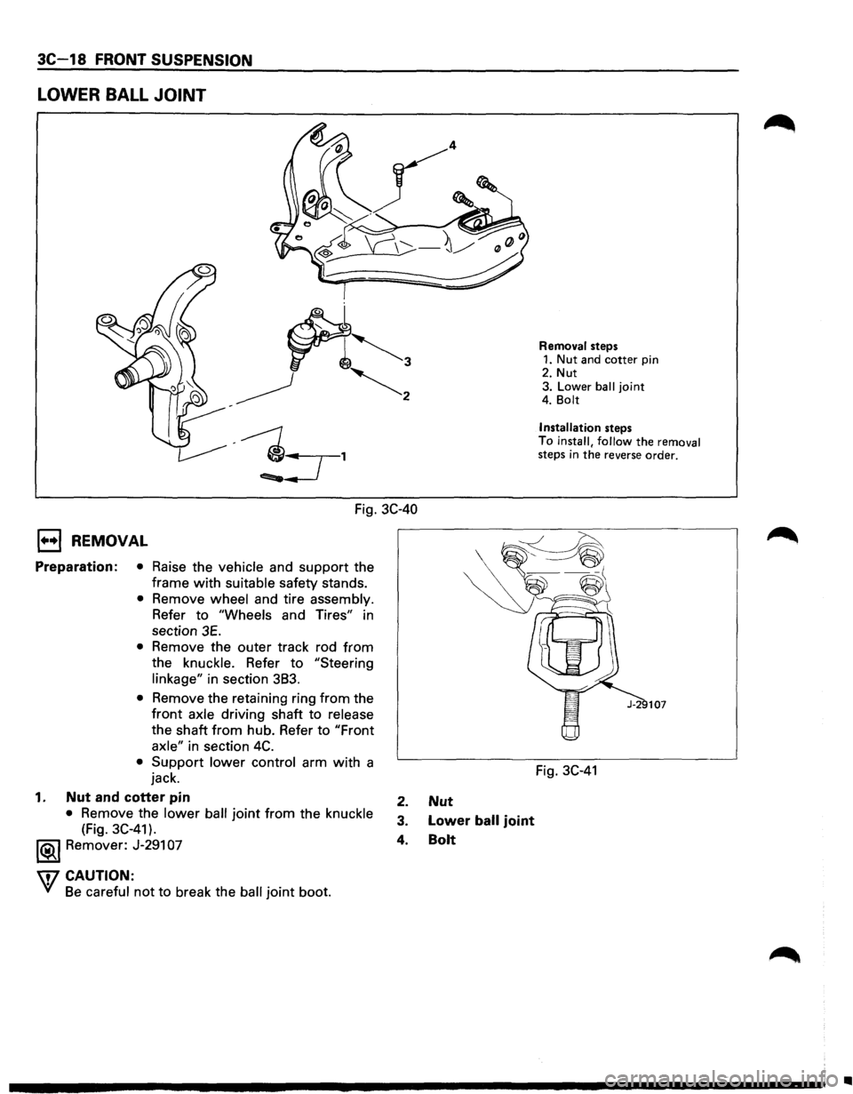
LOWER BALL JOINT
Fig. 3C-40
1••1 REMOVAL
Preparation: • Raise the vehicle and support the
frame
with suitable safety stands.
• Remove wheel and tire assembly.
Refer to "Wheels and Tires" in
section
3E.
• Remove the outer track rod from
the knuckle. Refer to "Steering
linkage"
in section 383.
• Remove the retaining ring from the
front axle driving shaft to release
the shaft from hub. Refer to "Front
axle"
in section 4C.
• Support lower control arm with a
jack.
1. Nut and cotter pin
• Remove the lower ball joint from the knuckle
(Fig. 3C-41).
1®..1 Remover: J-291 07
\f7 CAUTION:
VI Be careful not to break the ball joint boot.
2. Nut
3. Lower ball joint
4. Bolt
Removal steps 1. Nut and cotter pin
2. Nut
3. Lower
ball joint 4. Bolt
Installation
steps
To
install, follow the removal steps in the reverse order.
Fig. 3C-41
..
Page 183 of 1928
I L•IINSPECTION AND REPAIR
Make necessary parts replacement if wear, damage,
corrosion
or any other abnormal condition are found
through inspection.
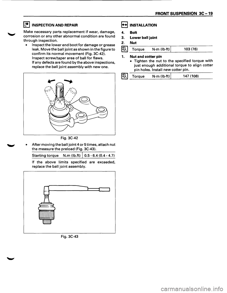
• Inspect the lower end boot for damage or grease
leak.
Move the ball joint as shown in the figure to
confirm its normal movement (Fig. 3C-42).
Inspect screw/taper area of ball for flaws.
If
any defects are found by the above inspections,
replace the ball
joint assembly with new one.
,--~:_,.--,',\ ,-...
~ .. :::: , \~-,
Fig. 3C-42
• After moving the ball joint 4 or Stimes, attach nut
the measure the preload (Fig. 3C-43).
Starting torque N.m (lb.ft) I 0.5-6.4 (0.4-4.7)
If the above limits specified are exceeded,
replace
the ball joint assembly.
Fig.
3C-43
FRONT SUSPENSION 3C-19
I••! INSTALLATION
4.
3.
2.
Bolt
Lower ball joint
Nut
I~I_To_r_:_q_ue __ N_·m_O_b_·ft_) Ll ___ 10_3_(7_6_) __ _
1. Nut and cotter pin
• Tighten the nut to the specified torque with
just enough additional torque to align cotter
pin
holes. Install new cotter pin.
~~~ Torque N·m (lb·ft) I 147 (108) --~----~-----------
Page 197 of 1928
J-39792-1
Fig. 30-19
1•+1 INSTALLATION
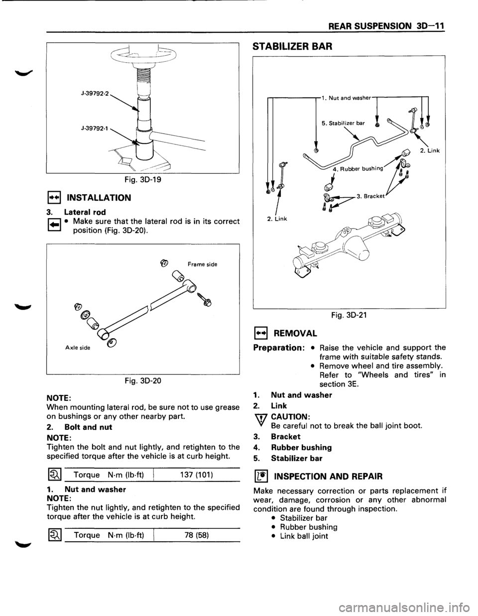
3. Lateral rod
~ • Make sure that the lateral rod is in its correct
~ position (Fig. 30-20).
Frame side
Axle side
Fig. 30-20
NOTE:
When mounting lateral rod, be sure not to use grease
on bushings
or any other nearby part.
2. Bolt and nut
NOTE:
Tighten the bolt and nut lightly, and retighten to the
specified torque after the
vehicle is at curb height.
~~~ Torque N·m (lb·ft)
1. Nut and washer
NOTE:
137 (101)
Tighten the nut lightly, and retighten to the specified
torque after the
vehicle is at curb height.
1~1 Torque N·m (lb·ft) 78 (58)
REAR SUSPENSION 30-11
STABILIZER BAR
2. Link
Fig. 30-21
EJ REMOVAL
Preparation: • Raise the vehicle and support the
frame
with suitable safety stands.
• Remove wheel and tire assembly.
Refer
to "Wheels and tires" in
section
3E.
1. Nut and washer
2. Link
\fl CAUTION:
VI Be careful not to break the ball joint boot.
3. Bracket
4. Rubber bushing
5. Stabilizer bar
[!] INSPECTION AND REPAIR
Make necessary correction or parts replacement if
wear, damage, corrosion or any other abnormal
condition are found through inspection.
• Stabilizer bar
• Rubber bushing
• Link ball joint
Page 354 of 1928
5A2-4 DISC BRAKES
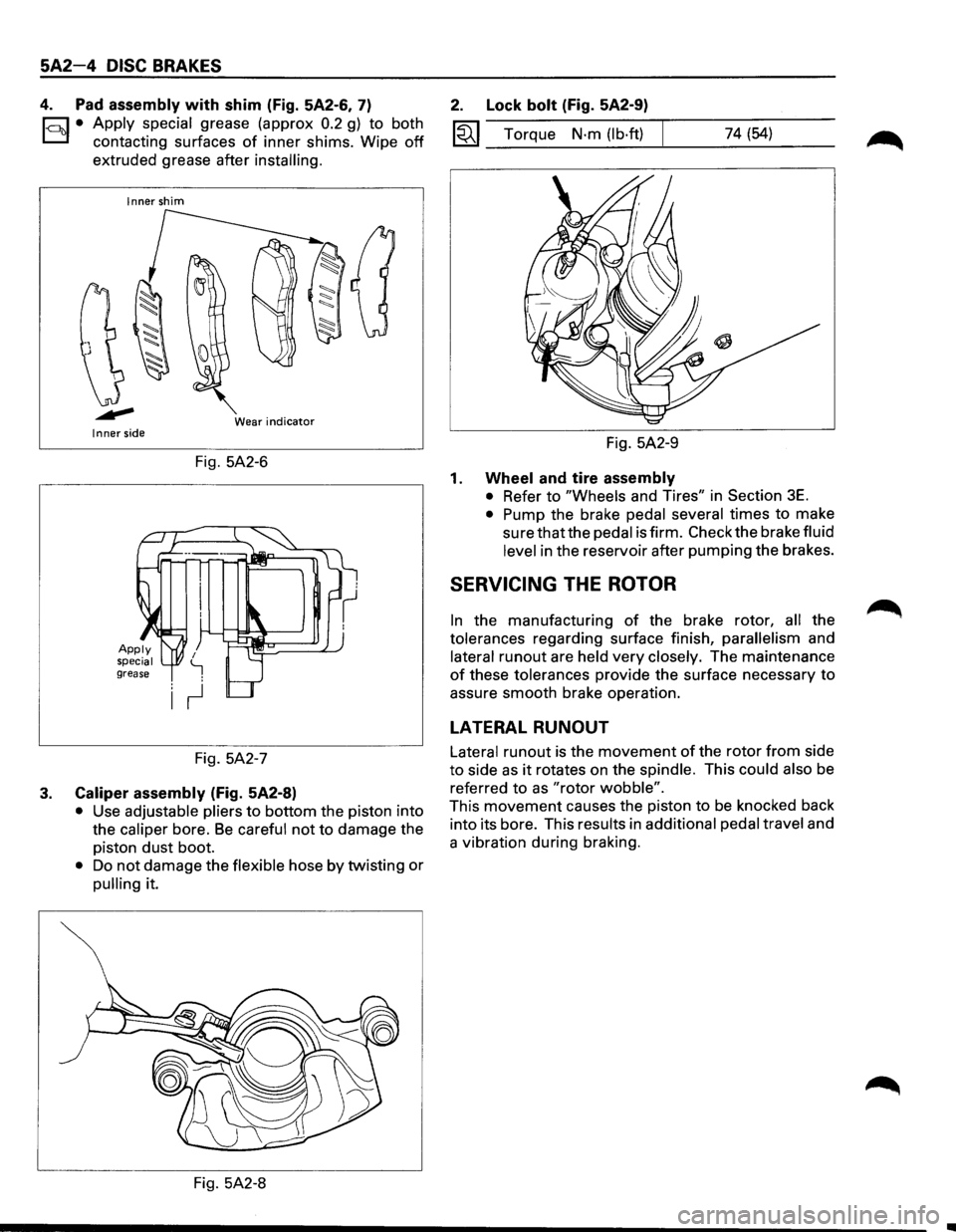
4. Pad assembly with shim (Fig. 5A2-6, 7)
1-c::~t:.l• Apply ~pecial grease (approx 0.2 g) to both
contactmg surfaces
of inner shims. Wipe off
extruded grease after installing.
Inner shim
Wear
indicator Inner side
Fig. 5A2-6
Fig. 5A2-7
3. Caliper assembly (Fig. 5A2-8)
• Use adjustable pliers to bottom the piston into
the
caliper bore. Be careful not to damage the
piston
dust boot.
• Do not damage the flexible hose by twisting or
pulling it.
Fig. 5A2-8
2. Lock bolt (Fig. 5A2-9)
1«1 Torque N·m (lb·ft) 74 (54)
Fig. 5A2-9
1. Wheel and tire assembly
• Refer to "Wheels and Tires" in Section 3E.
• Pump the brake pedal several times to make
sure that the pedal is firm. Check the brake fluid
level in the reservoir after pumping the brakes.
SERVICING THE ROTOR
In the manufacturing of the brake rotor, all the
tolerances regarding surface finish,
parallelism and
lateral
runout are held very closely. The maintenance
of these tolerances provide the surface necessary to
assure smooth brake operation.
LATERAL RUNOUT
Lateral runout is the movement of the rotor from side
to side as it rotates on the spindle. This could also be
referred
to as "rotor wobble".
This movement causes the piston to be knocked back
into its bore. This results in
additional pedal travel and
a vibration during braking.
Page 356 of 1928
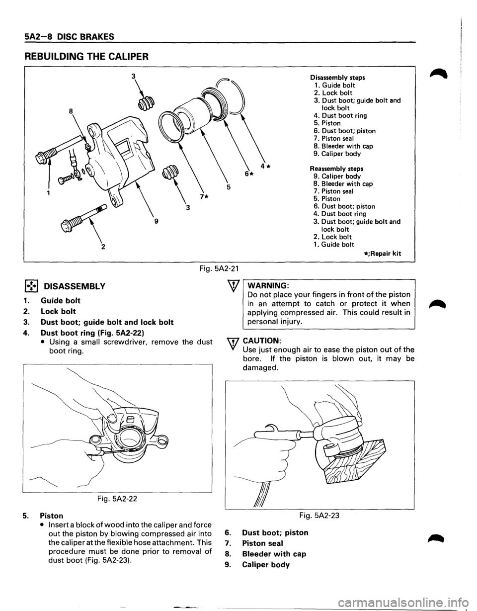
5A2-8 DISC BRAKES
REBUILDING THE CALIPER
8
3~
'
3
7* 1
~
9
2 Disassembly
steps
1. Guide
bolt 2. Lock bolt
3. Dust boot; guide bolt and lock bolt 4. Dust boot ring
5. Piston
6. Dust
boot; piston
7. Piston
seal
8. Bleeder with cap
9. Caliper body
Reassembly steps
9.
Caliper body
8. Bleeder with cap
7. Piston seal 5. Piston
6. Dust boot; piston
4. Dust
boot ring
3. Dust boot; guide bolt and
lock bolt 2. Lock bolt 1. Guide bolt
*;Repair kit
Fig. 5A2-21
l•!•l DISASSEMBL V
1. Guide bolt
2. Lock bolt
3. Dust boot; guide bolt and lock bolt
4. Dust boot ring (Fig. 5A2-22)
• Using a small screwdriver, remove the dust
boot ring.
Fig. 5A2-22
5. Piston
• Insert a block of wood into the caliper and force
out the piston by blowing compressed air into
the
caliper at the flexible hose attachment. This
procedure
must be done prior to removal of
dust boot (Fig. 5A2-23).
WARNING:
Do not place your fingers in front of the piston
in
an attempt to catch or protect it when
applying compressed air. This could result in
personal injury.
W CAUTION:
VI Use just enough air to ease the piston out of the
bore.
If the piston is blown out, it may be
damaged.
Fig. 5A2-23
6. Dust boot; piston
7. Piston seal
8. Bleeder with cap
9. Caliper body
Page 357 of 1928
ll .. •l INSPECTION AND REPAIR
Make necessary parts replacement, if wear, damage,
"'-"' corrosion or any other abnormal conditions are found
through inspection.
Check the following parts;
• Rotor
• Cylinder body
• Cylinder bore
• Piston
•
Guide bolt, Lock bolt
•
Support bracket
NOTE:
The piston seal, boot ring and dust boot are to be
replaced each time the caliper is overhauled. Discard
these used rubber parts and
replace with new ones.
l*!•l REASSEMBLY
9. Caliper body
8. Bleeder with cap
~~~ Torque N·m (lb·in) 8 (69)
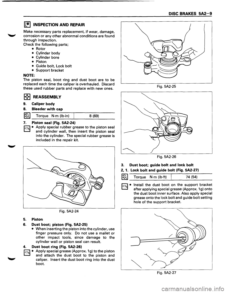
7. Piston seal (Fig. 5A2-24)
r.:;::'1 • Apply special rubber grease to the piston seal
0 and cylinder wall, then insert the piston seal
into the cylinder. The special rubber grease is
included in the repair kit.
Fig. 5A2-24
5. Piston
6. Dust boot; piston (Fig. 5A2-25)
• When inserting the piston into the cylinder, use
finger pressure
only. Do not use a mallet or
other impact tools, since damage to the
cylinder wall or piston seal can result.
4. Dust boot ring (Fig. 5A2-26)
r;::;:] • Apply special grease (Approx. 1 g) to the piston
0 and attach the dust boot to the piston and
caliper. Insert the dust boot ring into the dust
boot.
DISC BRAKES 5A2-9
Fig. 5A2-25
Fig. 5A2-26
3. Dust boot; guide bolt and lock bolt
2, 1. Lock bolt and guide bolt (Fig. 5A2-27)
~~~ Torque N·m (lb·ft) I 74 (54)
§)• Install the dust boot on the support bracket
after
applying special grease (Approx. 1 g) onto
the
dust boot inner surface. Also apply special
grease onto the lock bolt and guide bolt setting
hole of the support bracket.
Fig. 5A2-27
Page 359 of 1928
3. Caliper assembly
• Support the caliper assembly so that the brake
hose is
not stretched or damaged.
4. Pad assembly with shim
5. Clip
l·u·l INSTALLATION
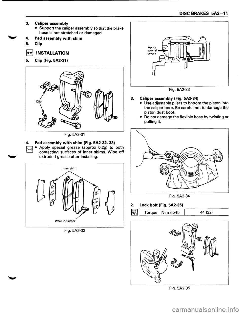
5. Clip (Fig. 5A2-31)
~ Clip
Fig. 5A2-31
4. Pad assembly with shim (Fig. 5A2-32, 33)
c=;:] • Apply special grease (approx 0.2g) to both
D contacting surfaces of inner shims. Wipe off
extruded grease after installing.
Inner shim
0
Wear indicator
Fig. 5A2-32
DISC BRAKES 5A2-11
Fig. 5A2-33
3. Caliper assembly (Fig. 5A2-34)
• Use adjustable pliers to bottom the piston into
the
caliper bore. Be careful not to damage the
piston dust boot.
• Do not damage the flexible hose by twisting or
pulling it.
Fig. 5A2-34
2. Lock bolt (Fig. 5A2-35)
~~~ Torque N·m (lb·ft) I
Fig. 5A2-35 44
(32)
Page 365 of 1928
DISC BRAKES 5A2-17
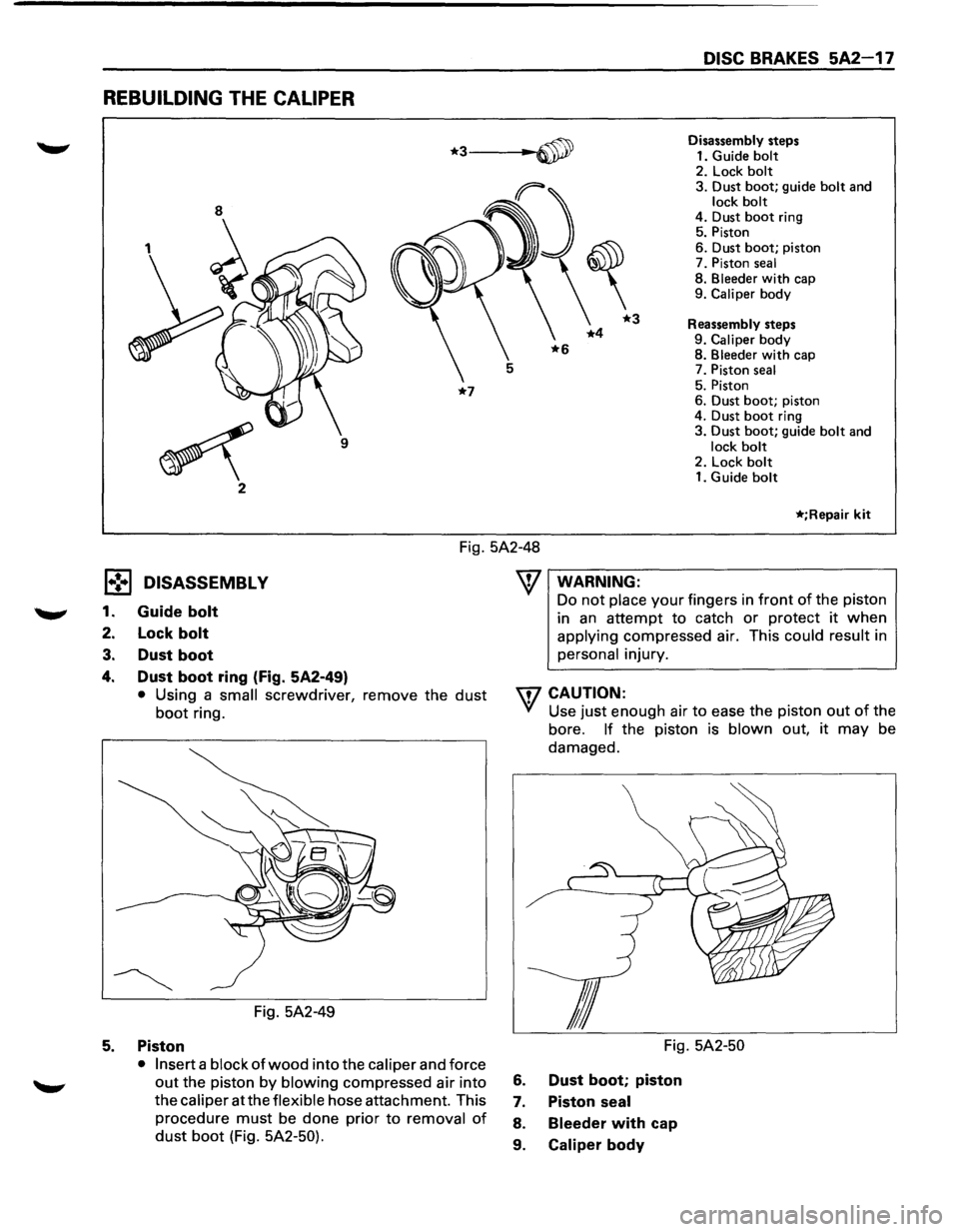
REBUILDING THE CALIPER
*3~ Disassembly steps
1. Guide
bolt
*7
9
2. Lock bolt 3. Dust boot; guide bolt and lock bolt 4. Dust boot ring
5. Piston
6. Dust
boot; piston
7. Piston seal
8. Bleeder with cap
9. Caliper body
Reassembly steps
9.
Caliper body
8. Bleeder with cap
7. Piston seal
5. Piston
6. Dust boot; piston
4. Dust boot ring
3. Dust
boot; guide bolt and lock bolt
2. Lock bolt 1. Guide bolt
*;Repair kit
Fig. 5A2-48
l•!•l DISASSEMBLY
1. Guide bolt
2. Lock bolt
3. Dust boot
4. Dust boot ring (Fig. 5A2-49)
• Using a small screwdriver, remove the dust
boot ring.
Fig. 5A2-49
5. Piston
• Insert a block of wood into the caliper and force
out the piston by blowing compressed air into
the caliper at the
flexible hose attachment. This
procedure
must be done prior to removal of
dust boot (Fig. 5A2-50).
WARNING:
Do not place your fingers in front of the piston
in
an attempt to catch or protect it when
applying compressed air. This could result in
personal injury.
\f7 CAUTION:
VI Use just enough air to ease the piston out of the
bore.
If the piston is blown out, it may be
damaged.
Fig.
5A2-50
6. Dust boot; piston
7. Piston seal
8. Bleeder with cap
9.
Caliper body
Page 366 of 1928
![ISUZU TROOPER 1995 User Guide 5A2-18 DISC BRAKES
(1!] INSPECTION AND REPAIR
Make necessary parts replacement, if wear, damage,
corrosion
or any other abnormal conditions are found
through inspection.
Check the
followi](/img/61/57183/w960_57183-365.png "ISUZU TROOPER 1995 User Guide 5A2-18 DISC BRAKES
(1!] INSPECTION AND REPAIR
Make necessary parts replacement, if wear, damage,
corrosion
or any other abnormal conditions are found
through inspection.
Check the
followi")
5A2-18 DISC BRAKES
(1!] INSPECTION AND REPAIR
Make necessary parts replacement, if wear, damage,
corrosion
or any other abnormal conditions are found
through inspection.
Check the
following parts;
• Rotor
• Cylinder body
• Cylinder bore
• Piston
• Slide
pin
• Support bracket
NOTE:
The piston dust seal and dust boot are to be replaced
each time the caliper is overhauled. Discard these
used rubber parts and
replace with new ones.
1•! .. 1 REASSEMBLY
9. Caliper body
8. Bleeder with cap
1~1 Torque N·m (lb·in) 8 (69)
7. Piston seal (Fig. 5A2-51)
r:::;] • Apply special rubber grease to the piston seal
D and cylinder wall, then insert the piston seal
into the cylinder. The special rubber grease is
included in the repair kit.
Fig. 5A2-51
5. Piston
6. Dust boot; piston (Fig. 5A2-52)
• When inserting the piston into the cylinder, use
finger pressure
only. Do not use a mallet or
other impact tools, since damage to the
cylinder wall or piston seal can result.
4. Dust boot ring (Fig. 5A2-53)
r:::;] • Apply special grease (Approx. 1 g) to the piston
D and attach the dust boot to the piston and
caliper. Insert the dust boot ring into the dust
boot. Fig.
5A2-52
Fig. 5A2-53
3. Dust boot (Fig. 5A2-54)
r:::;] • Install the dust boot on the support bracket
D after applying special grease (Approx. 1 g) onto
the dust
boot inner surface. Also apply special
grease onto the lock bolt and guide bolt setting
hole of the support bracket.
2. Lock bolt
1. Guide bolt
Fig. 5A2-54
~~~ Torque N-m (lb·ft) 44 (32)
•
Page 838 of 1928
6E2-142 DRIVEABILITY AND EMISSIONS
CHART C-40-1
ELECTRONIC IGNITION (EI) MISFIRE AT IDLE
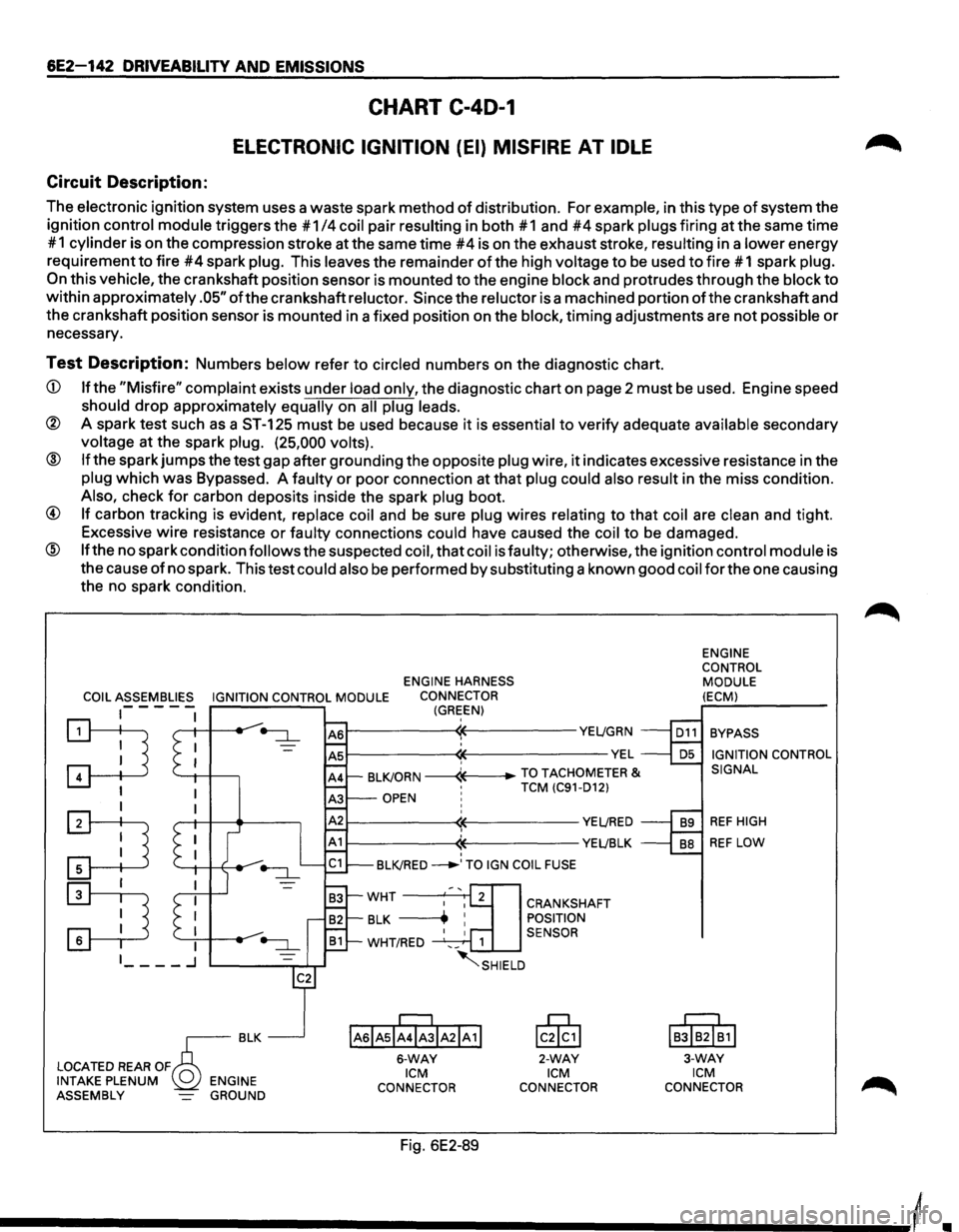
Circuit Description:
The electronic ignition system uses a waste spark method of distribution. For example, in this type of system the
ignition
control module triggers the #1 /4 coil pair resulting in both #1 and #4 spark plugs firing at the same time
# 1
cylinder is on the compression stroke at the same time #4 is on the exhaust stroke, resulting in a lower energy
requirement
to fire #4 spark plug. This leaves the remainder of the high voltage to be used to fire # 1 spark plug.
On this vehicle, the crankshaft position sensor is mounted to the engine block and protrudes through the block to
within approximately .05" ofthe crankshaft reluctor. Since the reluctor is a machined portion ofthe crankshaft and
the crankshaft position sensor is mounted in a fixed position on the
block, timing adjustments are not possible or
necessary.
Test Description: Numbers below refer to circled numbers on the diagnostic chart.
CD If the "Misfire" complaint exists under load only, the diagnostic chart on page 2 must be used. Engine speed
should drop approximately equally on all plug leads.
® A spark test such as a ST-125 must be used because it is essential to verify adequate available secondary
voltage at the spark plug. (25,000 volts).
@ If the spark jumps the test gap after grounding the opposite plug wire, it indicates excessive resistance in the
plug which was Bypassed. A faulty or poor connection at that plug could also result in the miss condition.
Also, check for carbon deposits inside the spark plug boot.
@ If carbon tracking is evident, replace coil and be sure plug wires relating to that coil are clean and tight.
Excessive
wire resistance or faulty connections could have caused the coil to be damaged.
@ If the no spark condition follows the suspected coil, that coil is faulty; otherwise, the ignition control module is
the cause
of no spark. This test could also be performed by substituting a known good coil for the one causing
the no spark condition.
ENGINE HARNESS
COIL ASSEMBLIES IGNITION CONTROL MODULE CONNECTOR
1-- - - -(GREEN)
~ '--1-1 -+---,
I
:TI
:D
r---------~~----------YE~GRN
~--------~~-------------VEL ' BLKJORN -----4---+-TO TACHOMETER & •
TCM (C91-D12) OPEN ! ' r---------~~----------YE~RED
r-----------<1~----------YEL!BLK ' BLKJRED ___..,TO IGN COIL FUSE
IAsiAsl;rJIA21A 1!
6-WAY ICM
CONNECTOR
Fig. 6E2-89
CRANKSHAFT
POSITION
SENSOR
lc0§,1
2-WAY ICM
CONNECTOR ENGINE
CONTROL
MODULE
(ECM)
BYPASS IGNITION CONTROL
SIGNAL
REF HIGH
REF LOW
IB!IB2I~1I
3-WAY ICM CONNECTOR