boot ISUZU TROOPER 1995 Owner's Manual
[x] Cancel search | Manufacturer: ISUZU, Model Year: 1995, Model line: TROOPER, Model: ISUZU TROOPER 1995Pages: 1928
Page 840 of 1928
6E2-144 DRIVEABILITY AND EMISSIONS
CHART C-40-2
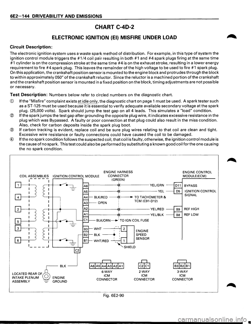
ELECTRONIC IGNITION (EI) MISFIRE UNDER LOAD
Circuit Description:
The electronic ignition system uses a waste spark method of distribution. For example, in this type of system the
ignition
control module triggers the # 1/4 coil pair resulting in both # 1 and #4 spark plugs firing at the same time
# 1 cylinder is on the compression stroke at the same time #4 is on the exhaust stroke, resulting in a lower energy
requirement
to fire #4 spark plug. This leaves the remainder of the high voltage to be used to fire #1 spark plug.
On this application, the crankshaft position sensor is mounted to the engine block and protrudes through the block
to within approximately 050" of the crankshaft reluctor. Since the reluctor is a machined portion of the crankshaft
and the crankshaft position sensor is mounted in a fixed position on the
block, timing adjustments are not possible
or necessary.
Test Description: Numbers below refer to circled numbers on the diagnostic chart.
CD If the "Misfire" complaint exists at idle only, the diagnostic chart on page 1 must be used. A spark tester such
as a ST-125 must be used because it is essential to verify adequate available secondary voltage at the spark
plug. (25,000 volts). Spark should jump the test gap on all 4 leads. This simulates a "load" condition.
® If the spark jumps the test gap after grounding the opposite plug wire, it indicates excessive resistance in the
plug which was Bypassed. A faulty or poor connection at that plug could also result in the miss condition.
Also, check for carbon deposits inside the spark plug boot.
® If carbon tracking is evident, replace coil and be sure plug wires relating to that coil are clean and tight.
Excessive
wire resistance or faulty connections could have caused the coil to be damaged.
® If the no spark condition follows the suspected coil, that coil is faulty, otherwise, the ignition control module is
the cause
of no spark. This test could also be performed by substituting a known good coil for the one causing
the no spark condition.
COIL ASSEMBLIES IGNITION CONTROL MODULE
ENGINE HARNESS
CONNECTOR
(GREEN) -----
:TI '--+I -l-----,
I
:TI
~
~--------~~-----------YE~GRN
~--------~~--------------VEL ' BLK/RED ------«--TO TACHOMETER &
OPEN ' TCM (C91-D12)
~--------~~-----------YE~RED
1------------((-----------YE~BLK ' BLK/ORN_.' TO IGN COIL FUSE
ENGINE SPEED
1 SENSOR
~SHIELD
IAsiAsii4ibiA21A11
6-WAY ICM
CONNECTOR
Fig. 6E2-90
lcik,l
2-WAY ICM
CONNECTOR ENGINE
CONTROL
MODULE(ECM)
BYPASS
IGNITION CONTROL
SIGNAL
REF HIGH
REF LOW
I
BJIB2I~1I
3-WAY ICM
CONNECTOR
•
Page 1151 of 1928
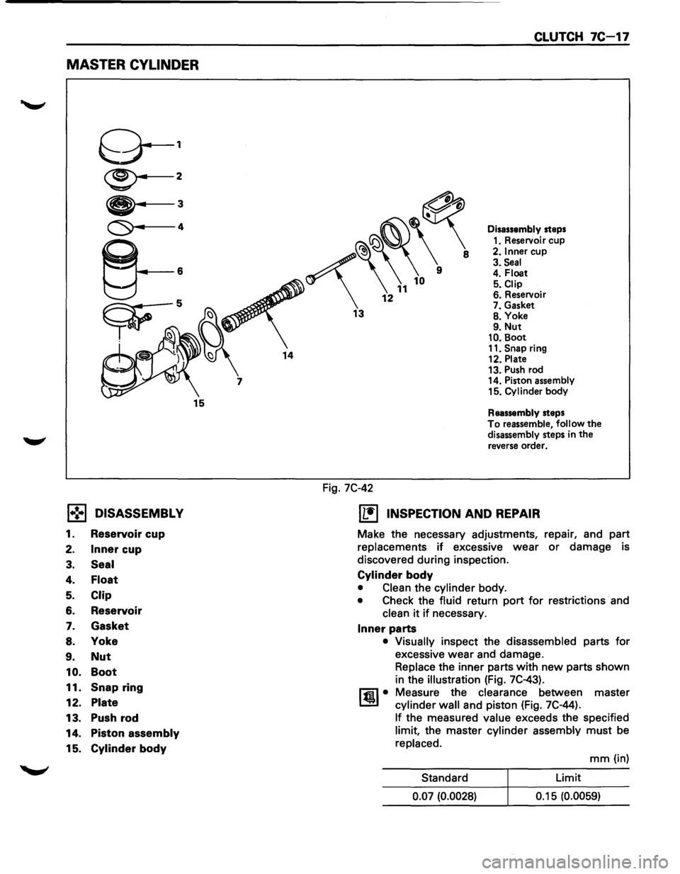
MASTER CYLINDER
l•!•l DISASSEMBLY
1. Reservoir cup
2. Inner cup
3. Seal
4. Float
5. Clip
6. Reservoir
7. Gasket
8. Yoke
9. Nut
10. Boot
11. Snap ring
12. Plate
13. Push rod
14. Piston assembly
15. Cylinder body
..........
Fig. 7C-42
CLUTCH 7C-17
Disassembly steps
1. Reservoir cup
2. Inner cup
3. Seal 4. Float 5. Clip 6. Reservoir 7. Gasket 8. Yoke 9. Nut 10. Boot
11. Snap ring
12. Plate
13. Push rod
14. Piston assembly
15. Cylinder
body
Reassembly steps To reassemble, follow the disassembly steps in the
reverse order.
IL•I INSPECTION AND REPAIR
Make the necessary adjustments, repair, and part
replacements
if excessive wear or damage is
discovered during inspection.
Cylinder body
• Clean the cylinder body.
• Check the fluid return port for restrictions and
clean
it if necessary.
Inner parts
• Visually inspect the disassembled parts for
excessive wear and damage.
Replace the inner parts
with new parts shown
in the
illustration (Fig. 7C-43).
ltil• Measure the clearance between master
cylinder
wall and piston (Fig. 7C-44).
If the measured value exceeds the specified
limit, the master cylinder assembly
must be
replaced.
mm (in)
Standard Limit
0.07
(0.0028) 0.15 (0.0059)
Page 1152 of 1928

7C-18 CLUTCH
Fig. 7C-43
Fig. 7C-44
SLAVE CYLINDER
~\
4
5
3
l•!•l REASSEMBLY
To reassemble, follow the disassembly steps in the
reverse
order, noting the following points:
1. Cylinder body
D • lmmHrse the cylinder body in clean brake fluid
L:::J (Fig. 7C-45).
2. Piston assembly
D Before installing, apply a thin coat of rubber
L:::J grease to the piston. Install cup in groove in
IE41 piston with the lip turned to front of cylinder.
Use care to prevent damaging the lip of the piston
seat.
Fig.
7C-45
Disassembly steps
1. Boot
2. Push rod
3. Piston and piston
cup 4. Spring
5. Cylinder body
Reassembly steps
To reassemble, follow the disassembly steps in the reverse order.
Fig. 7C-46
•
Page 1153 of 1928
l.-!•1 DISASSEMBLY
1. Boot
2. Push rod
3. Piston and piston cup
4.
Spring
5. Cylinder body
IL•I INSPECTION AND REPAIR
Make the necessary adjustments, repairs, and part
replacements
if excessive wear or damage is
discovered during inspection.
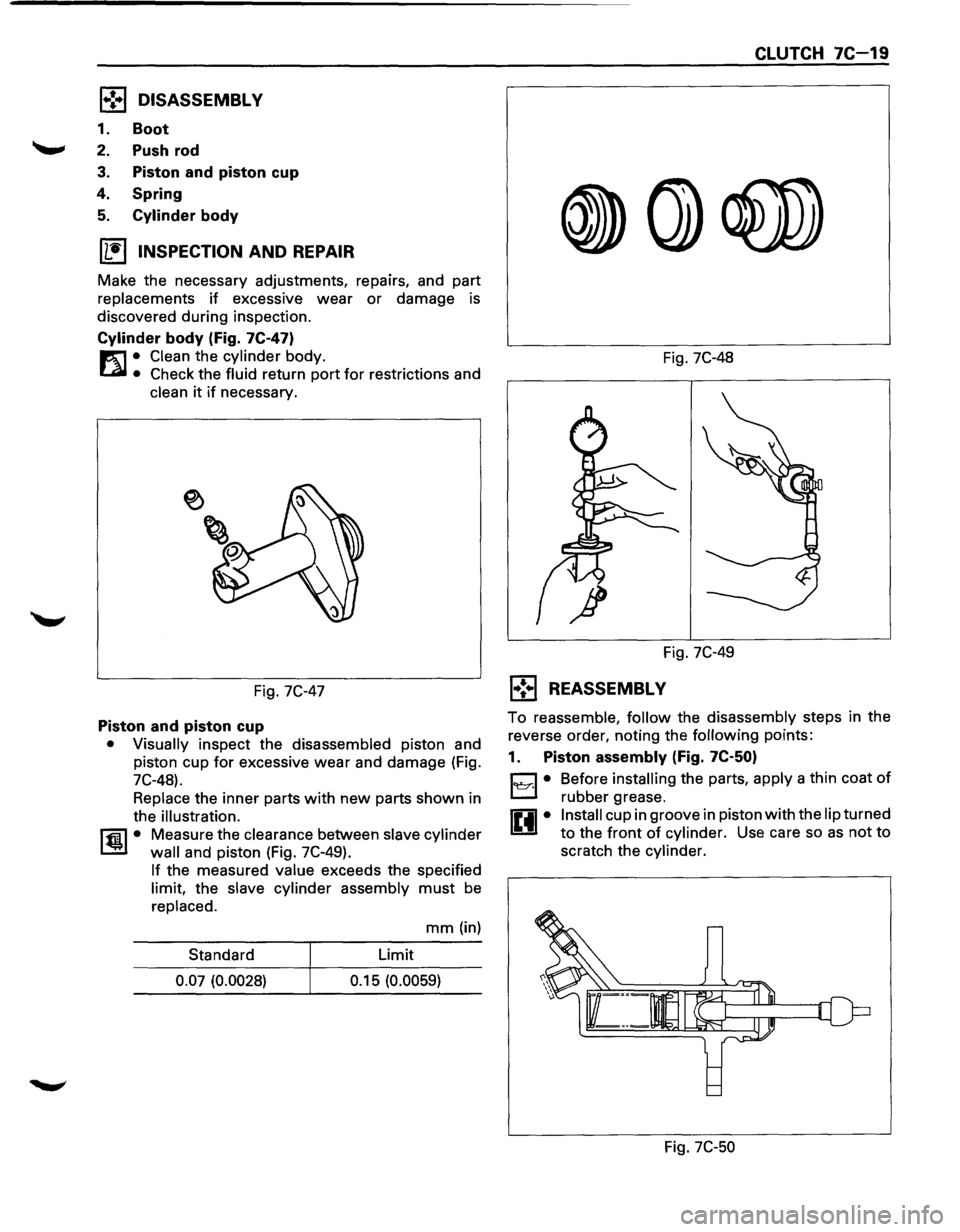
Cylinder body (Fig. 7C-47)
E'1 • Clean the cylinder body.
Lal • Check the fluid return port for restrictions and
clean it if necessary.
Fig. 7C-47
Piston and piston cup
• Visually inspect the disassembled piston and
piston cup
for excessive wear and damage (Fig.
7C-48).
Replace the inner parts
with new parts shown in
the
illustration.
l'fil • Measure the clearance between slave cylinder
l.!!!l wall and piston (Fig. 7C-49).
If the measured value exceeds the specified
limit, the slave cylinder assembly
must be
replaced.
mm (in)
Standard Limit
0.07 (0.0028) 0.15 (0.0059)
Fig. 7C-48
Fig. 7C-49
l•!.-1 REASSEMBLY CLUTCH
7C-19
To
reassemble, follow the disassembly steps in the
reverse order, noting the
following points:
1. Piston assembly (Fig. 7C-50)
D • Before installing the parts, apply a thin coat of
L::::.l rubber grease.
0 • Install cup in groove in piston with the lip turned
U to the front of cylinder. Use care so as not to
scratch the cylinder.
Fig.
7C-50