brakes ISUZU TROOPER 1995 User Guide
[x] Cancel search | Manufacturer: ISUZU, Model Year: 1995, Model line: TROOPER, Model: ISUZU TROOPER 1995Pages: 1928
Page 251 of 1928
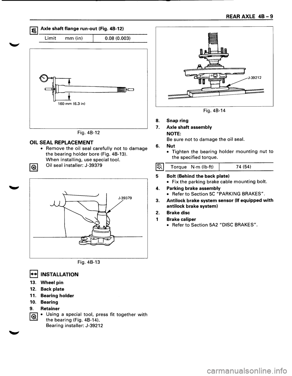
1 t!!.l Axle shaft flange run-out (Fig. 4B-12)
Limit mm (in) I 0.08 (0.003)
160 mm (6.3 in)
Fig. 4B-12
OIL SEAL REPLACEMENT
• Remove the oil seal carefully not to damage
the bearing holder bore (Fig. 4B-13).
When installing, use special tool.
1®1 Oil seal installer: J-39379
Fig. 4B-13
I••IINSTALLATION
13. Wheel pin
12. Back plate
11. Bearing holder
10. Bearing
9. Retainer
J-39379
1 ®I • Using a special tool, press fit together with
the bearing (Fig. 4B-14).
Bearing
installer: J-39212
8.
7.
6.
Fig. 4B-14
Snap ring
Axle shaft assembly
NOTE:
REAR AXLE 48-9
39212
Be sure not to damage the oil seal.
Nut
• Tighten the bearing holder mounting nut to
the specified torque.
I~I ___ T_o_rq_u_e __ N_·_m_(_lb_·f_t)~l _____ 7_4_(~5~4) ____ ___
5
4.
3.
2.
1
Bolt (Behind the back plate)
• Fix the parking brake cable mounting bolt.
Parking brake assembly
• Refer to Section 5C "PARKING BRAKES".
Antilock brake system sensor (If equipped with
antilock brake system)
Brake disc
Brake caliper
• Refer to Section 5A2 "DISC BRAKES".
Page 254 of 1928
48-12 REAR AXLE
1. Parking brake cable
• Remove the parking brake cable fastening clip
and disconnect the equalizer section. Refer
to
Section SC "PARKING BRAKES".
2. Nut
• Remove the bearing holder fixing nuts.
3. Axle shaft assembly
• Be sure notto damage the oil seal by axle shaft.
4.
Bolt and nut
• Remove differential carrier mounting bolts and
nuts.
5. Differential assembly
1••1 INSTALLATION
5. Differential assembly
• Clean the contact surfaces of the axle and
differential carrier.
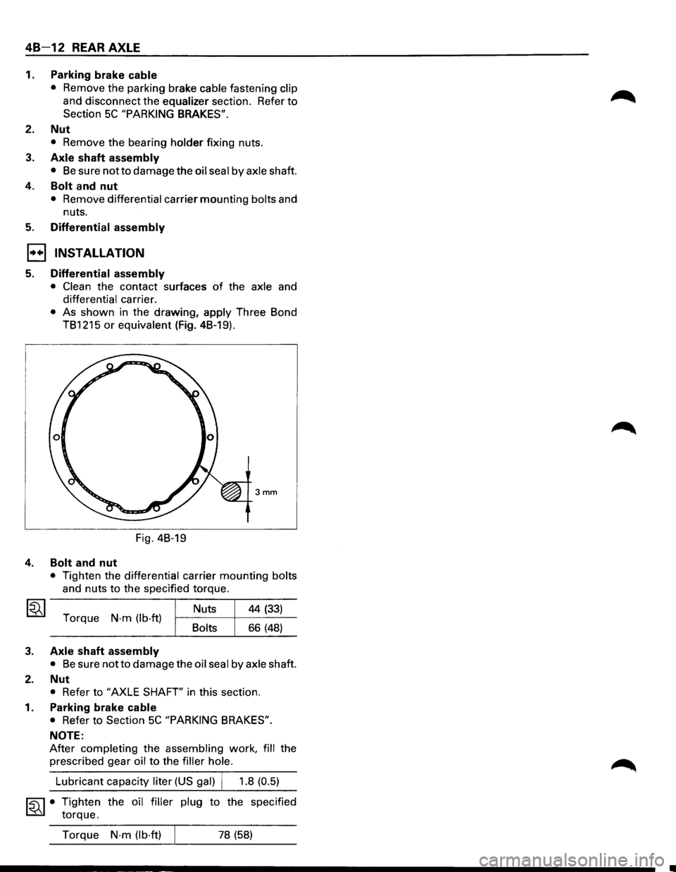
• As shown in the drawing, apply Three Bond
TB1215
or equivalent (Fig. 4B-19).
3mm
Fig. 4B-19
4. Bolt and nut
• Tighten the differential carrier mounting bolts
and nuts
to the specified torque.
Torque
N·m (lb·ft) Bolts Nuts
44
(33)
66 (48)
3. Axle shaft assembly
• Be sure notto damage
the oil seal by axle shaft.
2. Nut
• Refer to "AXLE SHAFT' in this section.
1. Parking brake cable
• Refer to Section 5C "PARKING BRAKES".
NOTE:
After completing the assembling work, fill the
prescribed gear
oil to the filler hole.
~·
Lubricant capacity liter (US gal) j 1.8 (0.5)
Tighten the oil filler plug to the specified
torque.
Torque
N·m (lb·ft) 78 (58)
Page 285 of 1928
l•!•l DISASSEMBLY
•
•
•
Jack up the vehicle and support it using jack
stands.
Remove the
tire and wheel.
Remove the drain bolt to drain differential oil.
NOTE:
•
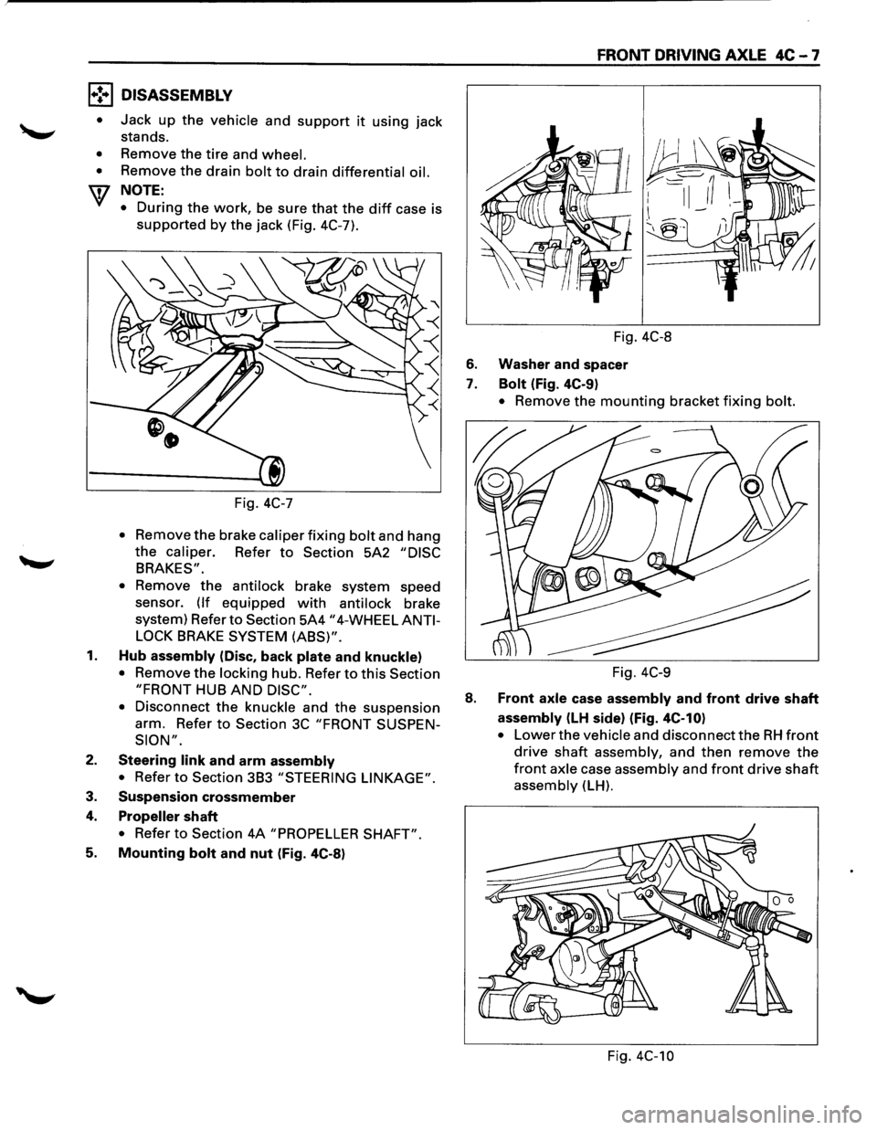
During the work, be sure that the diff case is
supported by the jack (Fig. 4C-7).
Fig.
4C-7
• Remov: the brake caliper fixing bolt and hang
the caliper. Refer to Section 5A2 "DISC
BRAKES".
•
Remove the antilock brake system speed
sensor.
(If equipped with antilock brake
system) Refer
to Section 5A4 "4-WHEEL ANTI
LOCK
BRAKE SYSTEM (ABS)".
1. Hub assembly (Disc, back plate and knuckle)
• Remove the locking hub. Refer to this Section
"FRONT HUB AND DISC".
•
Disconnect the knuckle and the suspension
arm. Refer
to Section 3C "FRONT SUSPEN
SION".
2. Steering link and arm assembly
• Refer to Section 3B3 "STEERING LINKAGE".
3. Suspension crossmember
4. Propeller shaft
• Refer to Section 4A "PROPELLER SHAFT".
5. Mounting bolt and nut (Fig. 4C-8)
FRONT DRIVING AXLE 4C-7
Fig. 4C-8
6. Washer and spacer
7. Bolt (Fig. 4C-9)
• Remove the mounting bracket fixing bolt.
Fig. 4C-9
8. Front axle case assembly and front drive shaft
assembly (LH side) (Fig. 4C-10)
• Lower the vehicle and disconnect the RH front
drive shaft assembly, and then remove the
front axle case assembly and front drive shaft
assembly (LH).
Fig. 4C-10
Page 286 of 1928
4C - 8 FRONT DRIVING AXLE
9. Front drive shaft assembly (RH)
l•!•l REASSEMBLY
9. Front drive shaft assembly (RH)
• Lay the assembly on the lower arm.
8. Front axle case assembly and front drive shaft
assembly (LH)
• Place the axle case on the jack, connect to the
front drive shaft assembly (RH) before
installing to the vehicle.
7. Bolt
• Tighten the mounting bracket fixing bolt to
the specified torque.
~~~ Torque N.m (lb.ft) I 116 (85)
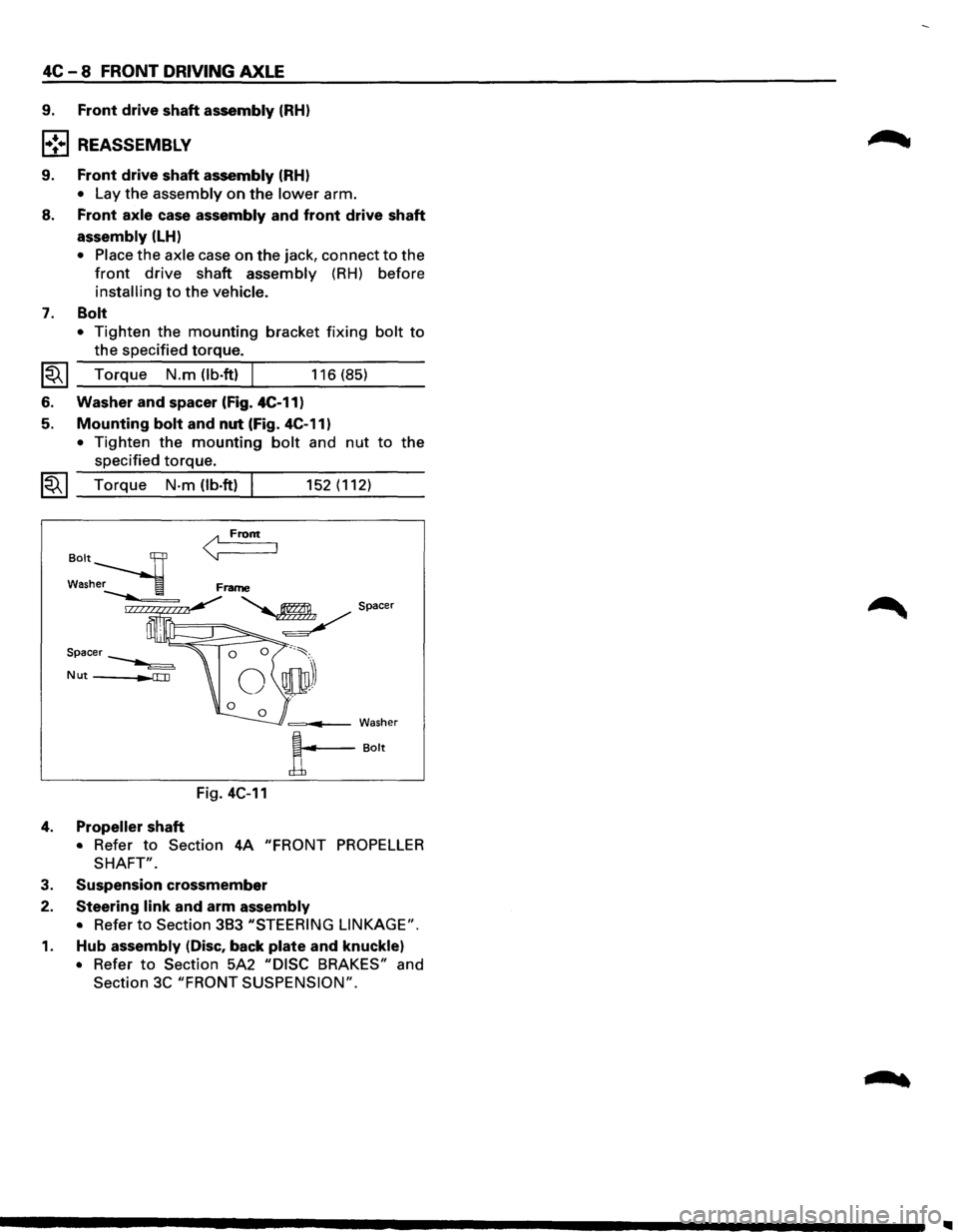
6. Washer and spacer (Fig. 4C-11)
5. Mounting bolt and nut (Fig. 4C-11)
• Tighten the mounting bolt and nut to the
specified torque.
~~~ Torque N·m (lb.ft) I 152 (112)
< From
=---Washer
A--Bolt
Fig. 4C-11
4. Propeller shaft
• Refer to Section 4A "FRONT PROPELLER
SHAFT".
3. Suspension crossmember
2. Steering link and arm assembly
• Refer to Section 383 "STEERING LINKAGE".
1. Hub assembly (Disc, back plate and knuckle)
• Refer to Section 5A2 "DISC BRAKES" and
Section
3C "FRONT SUSPENSION".
Page 307 of 1928
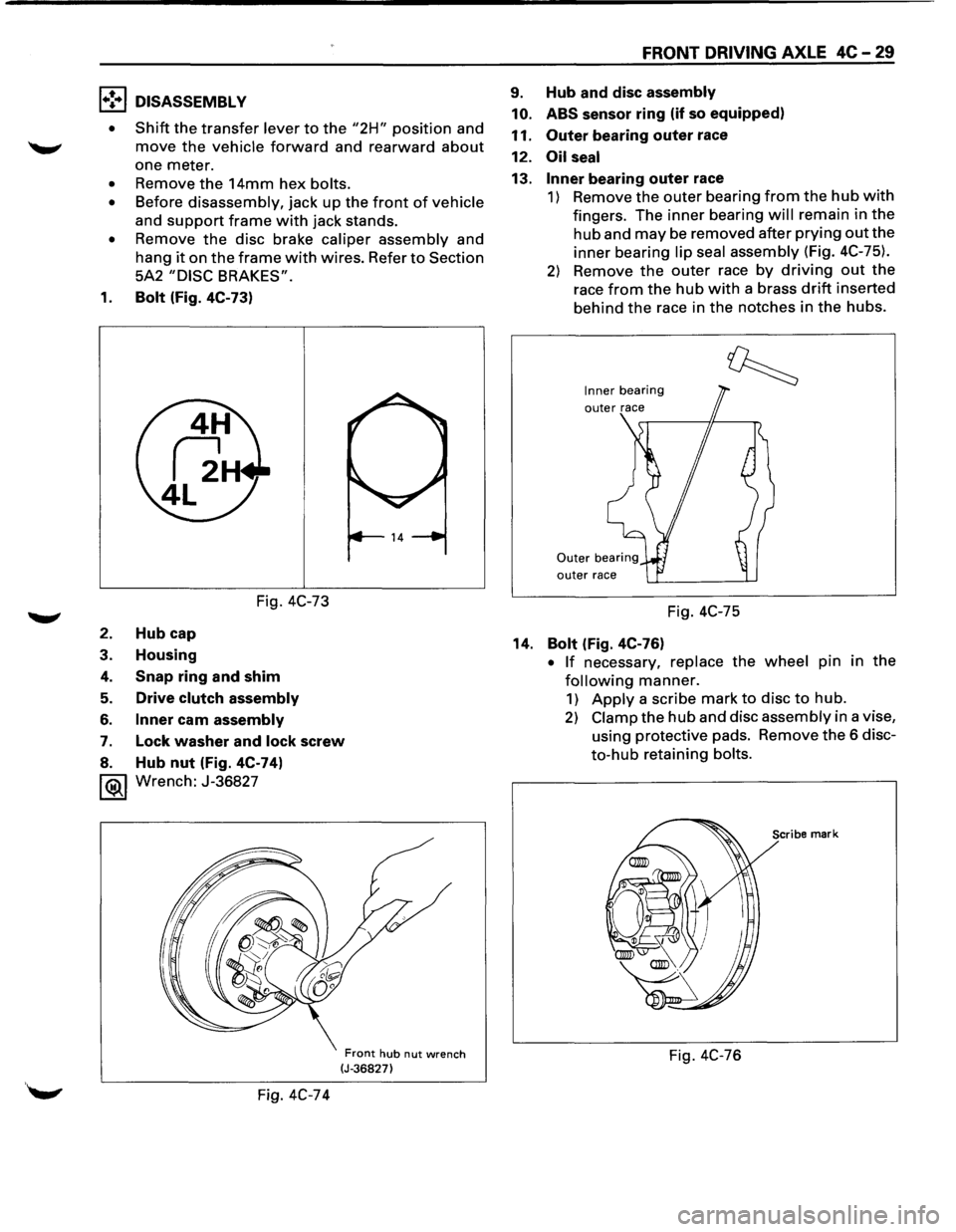
1•! .. 1 DISASSEMBLY
•
Shift the transfer lever to the "2H" position and
move the vehicle forward and rearward about
one meter.
• Remove the 14mm hex bolts.
• Before disassembly, jack up the front of vehicle
and
support frame with jack stands.
• Remove the disc brake caliper assembly and
hang
it on the frame with wires. Refer to Section
5A2
"DISC BRAKES".
1. Bolt (Fig. 4C-73)
Fig. 4C-73
2. Hub cap
3. Housing
4. Snap ring and shim
5. Drive clutch assembly
6. Inner cam assembly
7. Lock washer and lock screw
8. Hub nut (Fig. 4C-74)
1®.1 Wrench: J-36827
Fig. 4C-74
Front hub nut wrench (J-36827)
FRONT DRIVING AXLE 4C-29
9. Hub and disc assembly
10. ABS
sensor ring (if so equipped)
11.
Outer bearing outer race
12.
Oil seal
13. Inner bearing outer race
1) Remove the outer bearing from the hub with
fingers. The inner bearing will remain in the
hub and may be removed after prying out the
inner bearing lip seal assembly (Fig. 4C-75).
2) Remove the outer race by driving out the
race from the hub with a brass drift inserted
behind
the race in the notches in the hubs.
Inner bearing
outer race
Fig. 4C-75
14.
Bolt (Fig. 4C-76)
• If necessary, replace the wheel pin in the
following manner.
1) Apply a scribe mark to disc to hub.
2) Clamp the hub and disc assembly in a vise,
using protective pads. Remove
the 6 disc
to-hub retaining bolts.
Scribe mark
Fig. 4C-76
Page 308 of 1928
4C -30 FRONT DRIVING AXLE
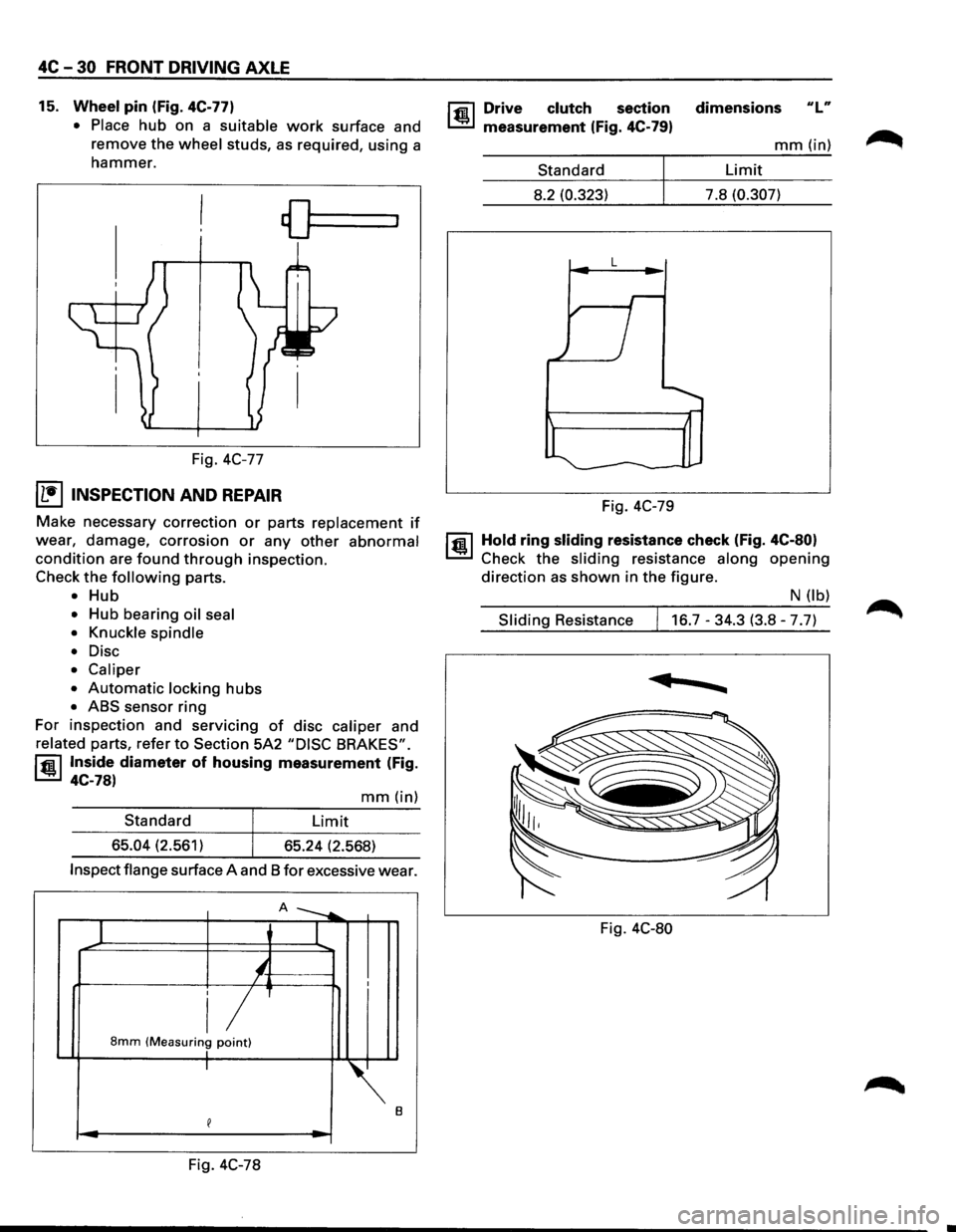
15. Wheel pin (Fig. 4C-77)
• Place
hub on a suitable work surface and
remove the
wheel studs, as required, using a
hammer.
Fig. 4C-77
I L•IINSPECTION AND REPAIR
Make necessary correction or parts replacement if
wear, damage, corrosion or any other abnormal
condition are found through inspection.
Check
the following parts.
• Hub
• Hub bearing oil seal
• Knuckle spindle
•
Disc
• Caliper
•
Automatic locking hubs
• ABS sensor ring
For inspection and servicing
of disc caliper and
related parts, refer to Section 5A2 "DISC BRAKES".
rfil Inside diameter of housing measurement (Fig.
~ 4C-78)
mm(in)
Standard Limit
65.04 (2.561)
65.24 (2.568)
Inspect flange surface A and 8 for excessive wear.
A ---....
1 I
'-/ I
i/ 8mm (Measuring point) I I
~.
e
Fig. 4C-78
rfil Drive clutch section
~ measurement (Fig. 4C-79)
Standard
8.2 (0.323)
L
Fig. 4C-79 dimensions
ulu
mm(in)
Limit
7.8
(0.307)
1@ 1 Hold ring sliding resistance check (Fig. 4C-80)
Check the sliding resistance along opening
direction as shown in the figure.
N (lb)
Sliding Resistance 16.7-34.3 (3.8-7.7)
......
Fig. 4C-80
Page 321 of 1928
HYDRAULIC BRAKES SA-1
BRAKES
w CAUTION:
• All
brake attaching fasteners are an important attaching part in that they could affect performance of vital
parts and systems, and/or could result in major repair expense. They must be replaced with one of the same
part
number or with an equivalent part if replacement becomes necessary. Do not use replacement parts of
lesser quality or substitute design. Torque values must be used as specified during reassembly to assure
proper retention
of these parts.
CONTENTS
Hydraulic Brakes . . . . . . . . . . . . . . . . . . . . . . . . . . . . . . . . . . . . . . . . . . . . . . . . . . . . . . . . . . . . . . Section SA
Brake Booster System ........................................................ Section 5A1
Disc Brakes . . . . . . . . . . . . . . . . . . . . . . . . . . . . . . . . . . . . . . . . . . . . . . . . . . . . . . . . . . . . . . . . . . Section 5A2
Rear
Wheel Antilock Brake System (RWAL) .................................... Section 5A3
4-Wheel Antilock Brake System (ABS) ......................................... Section 5A4
Parking Brakes . . . . . . . . . . . . . . . . . . . . . . . . . . . . . . . . . . . . . . . . . . . . . . . . . . . . . . . . . . . . . . . .
Section 5C
SECTION 5A
HYDRAULIC BRAKES
CONTENTS
Brake System Diagnosis ................ SA-2
Road
Testing the Brakes . . . . . . . . . . . . . . SA-2
Brake
Fluid Leaks . . . . . . . . . . . . . . . . . . . . SA-2
Warning Light Operation . . . . . . . . . . . . . SA-2
Antilock Brake System (RWAL or ABS) . SA- 2
Diagnosis of Brake System . . . . . . . . . . . . . . SA-3
On-Vehicle Service .................... SA- S
Filling Master Cylinder Reservoir . . . . . . . SA-S
Deterioration of Brake Fluid . . . . . . . . . . . SA-S
Leakage
of Brake Fluid . . . . . . . . . . . . . . . SA-S
Bleeding Brake Hydraulic System . . . . . . SA-S
Flushing Brake Hydraulic System . . . . . . SA-6
Brake Pipes
and Hoses . . . . . . . . . . . . . . . SA-6
Brake Hose
Inspection . . . . . . . . . . . . . . . SA-6
Brake Hose
Replacement . . . . . . . . . . . . . SA-7
Brake Pipe
Replacement . . . . . . . . . . . . . . SA-8
Combination Valve/P & B Valve . . . . . . . SA-9
Valve Replacement . . . . . . . . . . . . . . . . . . SA-1 0
Inspection of Brake Pad Lining . . . . . . . . SA-11
Inspection of Brake Rotors . . . . . . . . . . . . SA-11
Brake Pedal Assembly .................. SA-13 •
Checking Pedal Height ................ SA-13
Checking Pedal Travel ................ SA-13
Brake
Pedal Replacement ............. SA-14
Stoplight Switch Replacement ......... SA-1S
Master Cylinder Assembly ............... SA-16
General Description .................. SA-16
On-Vehicle Service ................... SA-17
Unit Repair .......................... SA-19
Main Data and Specifications ............ SA-21
General Specifications ................ SA-21
Torque Specifications ................ SA-21
Special Tools .......................... SA-22
Page 322 of 1928
SA-2 HYDRAULIC BRAKES
BRAKE SYSTEM DIAGNOSIS
ROAD TESTING THE BRAKES
Brake Test
Brakes should be tested on a dry, clean, reasonably
smooth and
level roadway. A true test of brake
performance cannot be made
if the roadway is
wet, greasy
or covered with loose dirt so that all
tires do not grip the road equally. Testing will also
be adversely affected if the roadway is crowned so
as to throw the weight of the vehicle toward
wheels on one side or if the roadway is so rough
that wheels tend to bounce. Test the brakes at dif
ferent vehicle speeds with both light and heavy
pedal pressure; however, avoid locking the wheels
and sliding the tires. Locked wheels and sliding
tires do not indicate brake efficiency, since heavily
braked but turning wheels will stop the vehicle in
less distance than locked wheels. More tire-to-road
friction is present
with a heavily braked turning tire
then
with a sliding tire.
The standard brake system is designed and
balanced
to avoid locking the wheels except at very high
deceleration
levels.
It
is designed this way because the shortest stopping
distance and best
control is achieved without brake
lock-up.
Because of high deceleration capability, a firmer pedal
may be felt at higher deceleration levels.
External Conditions That Affect Brake
Performance
1.
2.
3.
Tires: Tires having unequal contact and grip on
the road
will cause unequal braking. Tires must
be equally inflated, identical in size, and the tread
pattern
of right and left tires must be approxi
mately equal.
Vehicle loading:
A heavily loaded vehicle requires
more braking effort.
Wheel Alignment: Misalignment of the wheels,
particularly
in regard to excessive camber and
caster,
will cause the brakes to pull to one side.
BRAKE FLUID LEAKS
With engine running at idle and the transmission in
"Neutral", depress the brake pedal and hold a constant
foot pressure on the pedal. If pedal gradually falls
away with the constant pressure, the hydraulic system
may be leaking.
Check the master cylinder fluid level. While a slight
drop in reservoir level will result from normal lining
wear, an abnormally low level in reservoir indicates a
leak in the system. The hydraulic system may be
leaking internally as well as externally. Refer to
"Master Cylinder Inspection". Also, the system may
appear
to pass this test but still have slight leakage. If
fluid level
is normal, check the vacuum booster
push rod
length. If an incorrect length push rod is
found, adjust
or replace the push rod. Check the
brake
pedal travel and the parking brake adjust
ment.
When checking the
fluid level, the master cylinder fluid
level
may be low from the "MAX" mark if the front and
rear
linings are worn. This is not abnormal.
WARNING LIGHT OPERATION
When the ignition switch is in the START position,
the
"BRAKE" warning light should glow and go off
when the ignition switch returns to the ON position.
The
following conditions will activate the "BRAKE"
light:
1. Parking brake applied. The light should be on
whenever the parking brake is applied and the
ignition switch is on.
2. Low fluid level. A low fluid level in the master
cylinder will turn the "BRAKE" light on (Except
Rear
Wheel Antilock Brake System (RWAL)
model).
3. During engine cranking the "BRAKE" light
should
remain on. This notifies the driver that
the warning circuit is operating properly.
4. In the event of a front or rear system malfunc
tion (RWAL model only).
5. In the event of RWAL malfunction (RWAL
model only. Refer to Section 5A3).
ANTILOCK BRAKE SYSTEM (RWAL or
ABS}
Refer to Section 5A3 or 5A4 for inspection and di
agnosis procedure of the hydraulic unit.
..
Page 323 of 1928
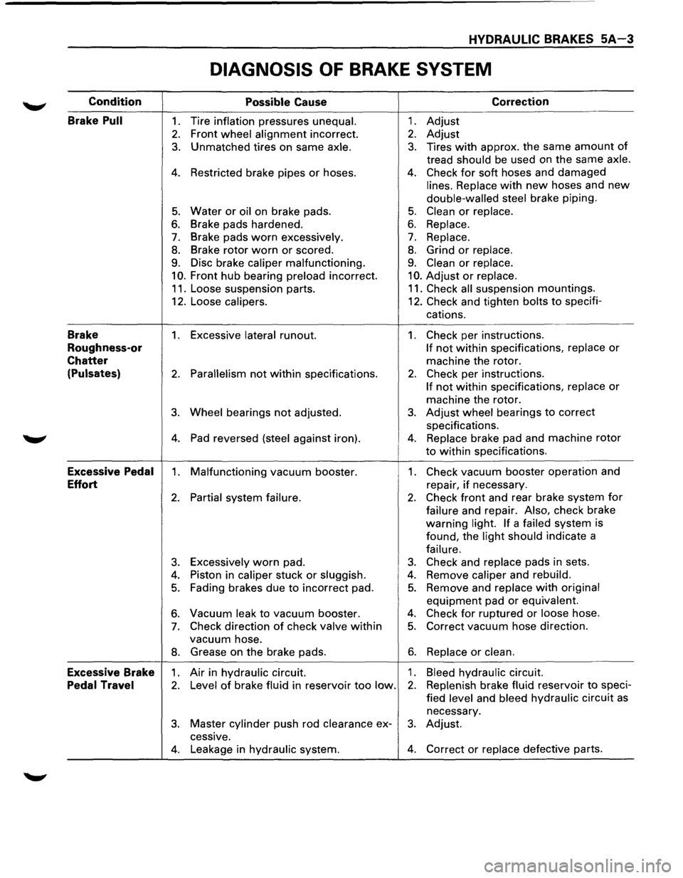
HYDRAULIC BRAKES 5A-3
DIAGNOSIS OF BRAKE SYSTEM
Condition
Possible Cause Correction
Brake
Pull 1. Tire inflation pressures unequal. 1. Adjust
2. Front wheel alignment incorrect. 2. Adjust
3. Unmatched tires on same axle. 3. Tires with approx. the same amount of
tread should be used on the same axle.
4. Restricted brake pipes or hoses. 4. Check for soft hoses and damaged
lines. Replace with new hoses and new
double-walled steel brake piping.
5. Water or oil on brake pads. 5. Clean or replace.
6. Brake pads hardened. 6. Replace.
7. Brake pads worn excessively. 7. Replace.
8. Brake rotor worn or scored. 8. Grind or replace.
9. Disc brake caliper malfunctioning. 9. Clean or replace.
10. Front hub bearing preload incorrect. 10. Adjust or replace.
11. Loose suspension parts. 11. Check all suspension mountings.
12. Loose
calipers. 12. Check and tighten bolts to specifi-
cations.
Brake 1. Excessive lateral runout. 1. Check per instructions.
Roughness-or If not within specifications, replace or
Chatter machine the rotor.
(Pulsates) 2. Parallelism not within specifications. 2. Check per instructions.
If not within specifications, replace or
machine the rotor.
3. Wheel bearings not adjusted. 3. Adjust wheel bearings to correct
specifications.
4. Pad reversed (steel against iron). 4. Replace brake pad and machine rotor
to within specifications.
Excessive Pedal 1. Malfunctioning vacuum booster. 1. Check vacuum booster operation and
Effort repair, if necessary.
2. Partial system failure. 2. Check front and rear brake system for
failure and repair. Also, check brake
warning
light. If a failed system
is
found, the
light should indicate a
failure.
3. Excessively worn pad. 3. Check and replace pads in sets.
4. Piston in caliper stuck or sluggish. 4. Remove caliper and rebuild.
5. Fading brakes due to incorrect pad. 5. Remove and replace with original
equipment pad or equivalent.
6. Vacuum leak to vacuum booster. 4. Check for ruptured or loose hose.
7. Check direction of check valve within 5. Correct vacuum hose direction.
vacuum hose.
8. Grease on the brake pads. 6. Replace or clean.
Excessive Brake 1. Air in hydraulic circuit. 1. Bleed hydraulic circuit.
Pedal Travel 2. Level of brake fluid in reservoir too low. 2. Replenish brake fluid reservoir to speci-
fied
level and bleed hydraulic circuit as
necessary.
3. Master cylinder push rod clearance ex-3. Adjust.
cessive.
4. Leakage in hydraulic system. 4. Correct or replace defective parts.
Page 324 of 1928
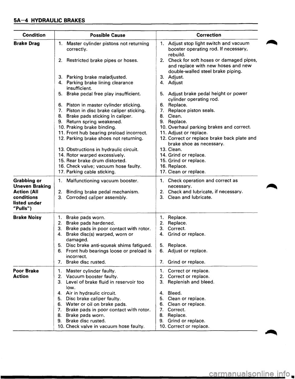
SA-4 HYDRAULIC BRAKES
Condition Possible Cause Correction
Brake Drag
1. Master cylinder pistons not returning 1. Adjust stop light switch and vacuum
correctly. booster operating rod. If necessary,
rebuild.
2. Restricted brake pipes or hoses. 2. Check for soft hoses or damaged pipes,
and
replace with new hoses and new
double-walled steel brake piping.
3. Parking brake maladjusted. 3. Adjust.
4. Parking brake lining clearance 4. Adjust
insufficient.
5. Brake pedal free play insufficient. 5. Adjust brake pedal height or power
cylinder operating rod.
6. Piston in master cylinder sticking. 6. Replace.
7. Piston in disc brake caliper sticking. 7. Replace piston seals.
8. Brake pads sticking in caliper. 8. Clean.
9. Return spring weakened. 9. Replace.
10. Praking brake binding. 10. Overhaul parking brakes and correct.
11. Front hub bearing preload incorrect. 11.
Adjust or replace.
12. Parking brake shoes not returning. 12.
Correct or replace brake back plate and
brake shoe
as necessary.
13. Obstructions in hydraulic circuit. 13. Clean.
14. Rotor warped excessively. 14.
Grind or replace.
15. Rear brake drum distorted. 15.
Grind or replace.
16. Check valve; vacuum hose faulty. 16. Replace.
17. Parking cable sticking. 17. Clean or replace.
Grabbing
or 1. Malfunctioning vacuum booster. 1. Check operation and correct as
Uneven Braking necessary.
Action
(All 2. Binding brake pedal mechanism. 2. Check and lubricate, if necessary.
conditions
3. Corroded caliper assembly. 3. Clean and lubricate.
listed
under
"Pulls")
Brake Noisy 1 . Brake pads worn. 1. Replace.
2. Brake pads hardened. 2. Replace.
3. Brake pads in poor contact with rotor. 3. Correct.
4. Brake disc(s) warped, worn or 4. Grind or replace.
damaged.
5. Disc brake anti-squeak shims fatigued. 5. Replace.
6. Front hub bearings loose or preload is 6. Adjust or replace.
incorrect.
7. Brake disc rusted. 7. Grind or replace.
Poor Brake 1. Master cylinder faulty. 1. Correct or replace.
Action 2. Vacuum booster faulty. 2. Correct or replace.
3. Level of brake fluid in reservoir too 3. Replenish and bleed.
low.
4. Air in hydraulic circuit. 4. Bleed.
5. Disc brake caliper faulty. 5. Clean or replace.
6. Water or oil on brake pads. 6. Clean or replace.
7. Brake pads in poor contact with rotor. 7. Correct.
8. Brake pads worn. 8. Replace.
9. Brake disc rusted. 9. Grind or replace.
10. Check valve in vacuum hose faulty. 10. Correct or replace.
•