brakes ISUZU TROOPER 1995 Owner's Guide
[x] Cancel search | Manufacturer: ISUZU, Model Year: 1995, Model line: TROOPER, Model: ISUZU TROOPER 1995Pages: 1928
Page 335 of 1928
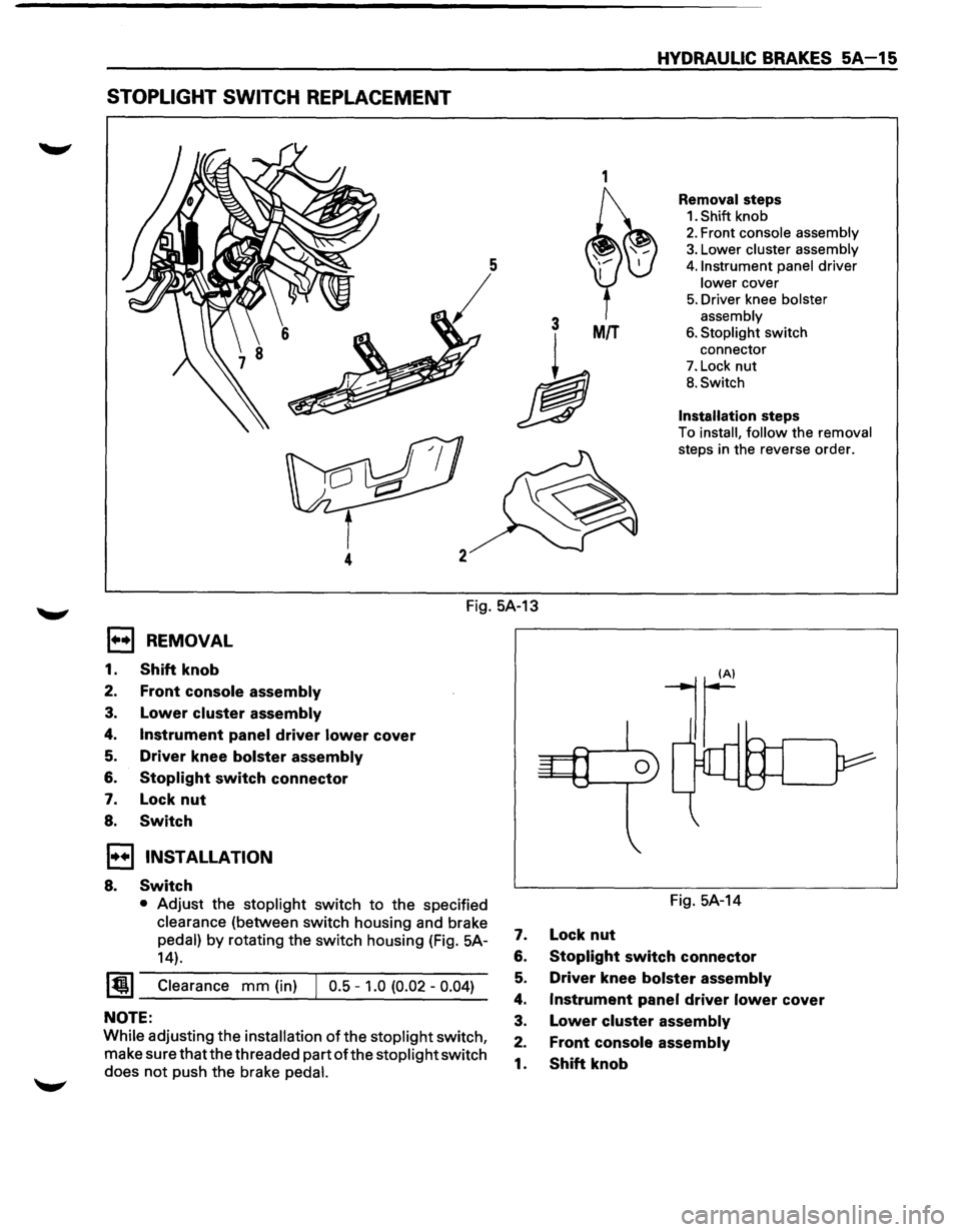
STOPLIGHT SWITCH REPLACEMENT
1
3 MIT
h
4
HYDRAULIC BRAKES SA-15
Removal steps
1. Shift knob
2. Front console assembly
3. Lower cluster assembly
4. Instrument panel driver
lower cover
5. Driver knee bolster
assembly
6. Stoplight switch
connector
7. Lock nut
B. Switch
Installation steps
To install, follow the removal
steps in the reverse order.
Fig. 5A-13
1••1 REMOVAL
1. Shift knob
2. Front console assembly
3. Lower cluster assembly
4. Instrument panel driver lower cover
5. Driver knee bolster assembly
6. Stoplight switch connector
7. Lock nut
8. Switch
1••1 INSTALLATION
8. Switch
• Adjust the stoplight switch to the specified
clearance (between switch housing and brake
pedal) by rotating the switch housing (Fig. 5A-
14).
~~~ Clearance mm (in) J 0.5 -1.0 (0.02 -0.04)
NOTE:
While adjusting the installation of the stoplight switch,
make sure that the threaded part
ofthe stoplight switch
does
not push the brake pedal.
Fig. 5A-14
7. Lock nut
6. Stoplight switch connector
5. Driver knee bolster assembly
4. Instrument panel driver lower cover
3. Lower cluster assembly
2. Front console assembly
1. Shift knob
Page 336 of 1928
SA 16 HYDRAULIC BRAKES
MASTER CYLINDER ASSEMBLY
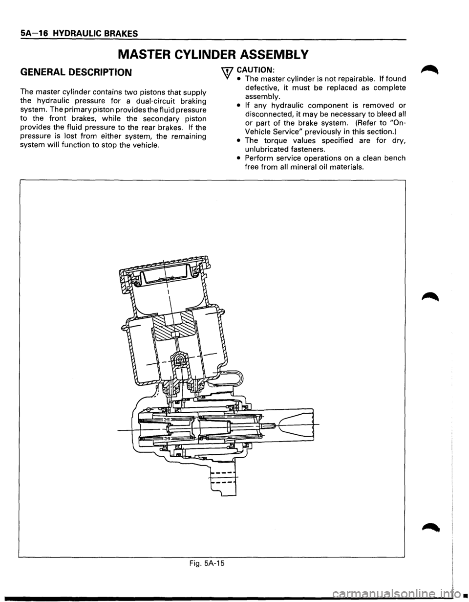
GENERAL DESCRIPTION
The master cylinder contains two pistons that supply
the hydraulic pressure
for a dual-circuit braking
system. The primary piston provides the fluid pressure
to the
front brakes, while the secondary piston
provides the fluid pressure
to the rear brakes. l.f ~he
pressure is lost from either system, the rema1n1ng
system will function to stop the vehicle.
\fl CAUTION:
VI • The master cylinder is not repairable. If found
defective,
it must be replaced as complete
assembly.
• If any hydraulic component is removed or
disconnected, it may be necessary to bleed all
or part of the brake system. (Refer to "On
Vehicle Service" previously in this section.)
• The torque values specified are for dry,
unlubricated fasteners.
• Perform service operations on a clean bench
free
from all mineral oil materials.
Fig.
5A-15
•
Page 337 of 1928
HYDRAULIC BRAKES 5A-17
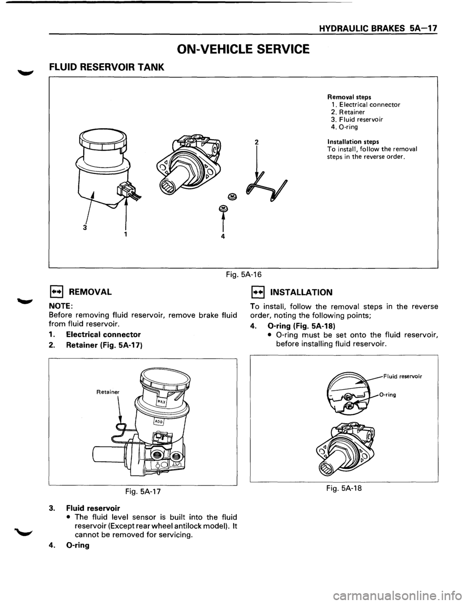
ON-VEHICLE SERVICE
FLUID RESERVOIR TANK
2
T 4
3 1
Removal steps
1. Electrical connector 2. Retainer
3. Fluid reservoir
4. 0-ring
Installation steps
To install, follow the removal steps in the reverse order.
Fig. 5A-16
1••1 REMOVAL
NOTE:
Before removing fluid reservoir, remove brake fluid
from fluid reservoir.
1. Electrical connector
2. Retainer (Fig. 5A-17)
Fig. 5A-17
3. Fluid reservoir
• The fluid level sensor is built into the fluid
reservoir (Except rear wheel anti lock model). It
cannot be removed for servicing.
4. 0-ring
1••1 INSTALLATION
To install, follow the removal steps in the reverse
order, noting the
following points;
4. 0-ring (Fig. 5A-18)
• 0-ring must be set onto the fluid reservoir,
before
installing fluid reservoir.
Fluid reservoir
0-ring
Fig. 5A-18
Page 338 of 1928
SA-18 HYDRAULIC BRAKES
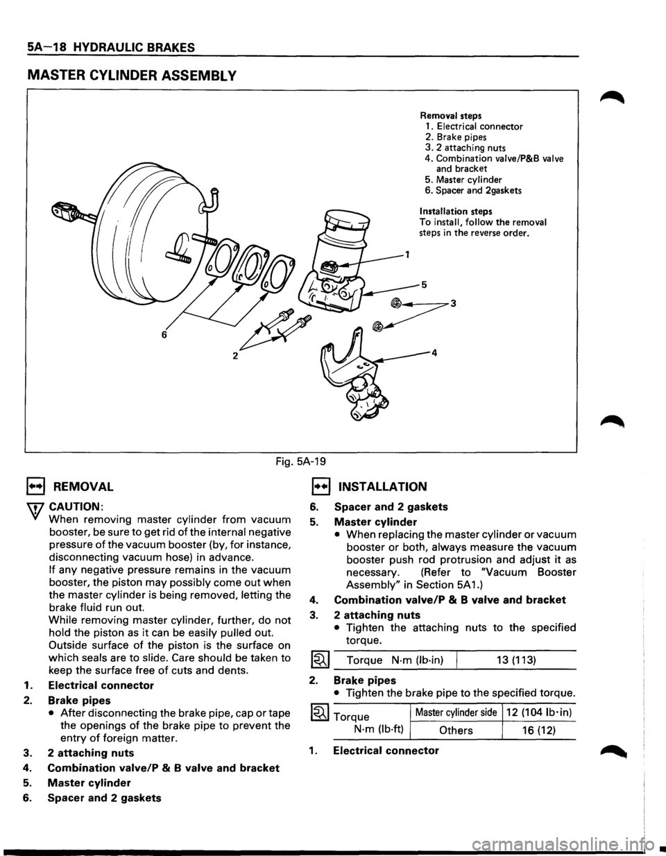
MASTER CYLINDER ASSEMBL V
6
2
Removal steps
1.
Electrical connector
2. Brake pipes
3. 2 attaching nuts
4. Combination valve/P&B
valve and bracket
5. Master cylinder
6.
Spacer and 2gaskets
Installation steps
To
install, follow the removal steps in the reverse order.
5
4
Fig. 5A-19
1••1 REMOVAL
\i7 CAUTION:
'V When removing master cylinder from vacuum
booster, be sure
to get rid of the internal negative
pressure
of the vacuum booster (by, for instance,
disconnecting vacuum hose) in advance.
If any negative pressure remains in the vacuum
booster, the piston
may possibly come out when
the master cylinder is being removed, letting the
brake fluid run out.
While removing master cylinder, further, do
not
hold the piston as it can be easily pulled out.
Outside surface of the piston is the surface on
which seals are to slide. Care should be taken to
keep the surface free of cuts and dents.
1.
Electrical connector
2. Brake pipes
• After disconnecting the brake pipe, cap or tape
the openings
of the brake pipe to prevent the
entry of foreign matter.
3. 2
attaching nuts
4. Combination valve/P & B valve and bracket
5. Master cylinder
6. Spacer and 2 gaskets
1••1 INSTALLATION
6. Spacer and 2 gaskets
5. Master cylinder
• When replacing the master cylinder or vacuum
booster
or both, always measure the vacuum
booster push rod protrusion and adjust
it as
necessary. (Refer to "Vacuum Booster
Assembly" in Section 5A 1.)
4. Combination valve/P & B valve and bracket
3. 2 attaching nuts
• Tighten the attaching nuts to the specified
torque.
~~~ Torque N·m (lb·in) 13 (113)
2. Brake pipes
• Tighten the brake pipe to the specified torque.
1~1 Torque Master cylinder side 12 (1041b·in)
N·m (lb·ft) Others
16 (12)
1. Electrical connector
•
Page 339 of 1928
HYDRAULIC BRAKES SA-19
UNIT REPAIR
MASTER CYLINDER
• The master cylinder is not repairable and must
be replaced as complete assembly if found
defective.
INSPECTION
Excessive brake pedal travel, malfunction or dragging
brake suggests
that the master cylinder is defective. In
such cases perform the following visual check.
IL•I Visual check
Make parts replacement as required if wear, distortion,
nicks, cuts, corrosion,
or other abnormal conditions
are
found through the following parts inspection;
• Master cylinder body
• Fluid reservoir
• 0-ring
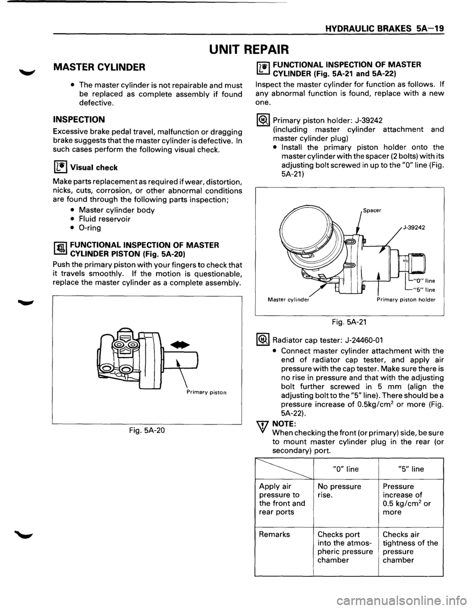
rfil FUNCTIONAL INSPECTION OF MASTER
l..!aJ CYLINDER PISTON (Fig. SA-20)
Push the primary piston with your fingers to check that
it travels smoothly. If the motion is questionable,
replace
the master cylinder as a complete assembly.
Primary piston
Fig. 5A-20
["j"1i"l FUNCTIONAL INSPECTION OF MASTER
I..!:::..J CYLINDER (Fig. 5A-21 and 5A-22)
Inspect the master cylinder for function as follows. If
any abnormal function is found, replace with a new
one.
1®.1 Primary piston holder: J-39242
(including master cylinder attachment and
master
cylinder plug)
• Install
the primary piston holder onto the
master
cylinder with the spacer (2 bolts) with its
adjusting
bolt screwed in up to the "0" line (Fig.
5A-21)
Master cylinder Primary piston holder
Fig. 5A-21
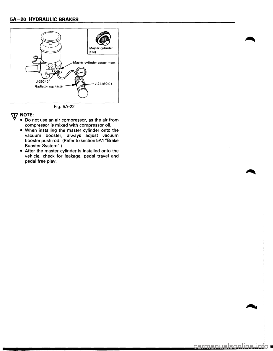
1®.1 Radiator cap tester: J-24460-01
•
Connect master cylinder attachment with the
end
of radiator cap tester, and apply air
pressure
with the cap tester. Make sure there is
no rise in pressure and
that with the adjusting
bolt further screwed in 5 mm (align the
adjusting
bolt to the "5" line). There should be a
pressure increase
of 0.5kg/cm2 or more (Fig.
5A-22).
\f7 NOTE:
VI When checking the front (or primary) side, be sure
to mount master cylinder plug in the rear (or
secondary) port.
~ "0" line "5" line
Apply air
No pressure Pressure
pressure
to rise. increase of
the front and 0.5 kg/cm2 or
rear ports more
Remarks Checks port Checks air
into the atmos-
tightness
of the
pheric pressure pressure
chamber chamber
Page 340 of 1928
SA-20 HYDRAULIC BRAKES
Fig. SA-22
\f/NOTE:
Master cy I i nder plug
J-24460..()1
VI • Do not use an air compressor, as the air from
compressor is mixed with compressor oil.
•
When installing the master cylinder onto the
vacuum booster,
always adjust vacuum
booster push rod. (Refer
to section SA 1 "Brake
Booster System".)
• After the master cylinder is installed onto the
vehicle, check for leakage, pedal travel and
pedal free play.
•
Page 341 of 1928
HYDRAULIC BRAKES 5A-21
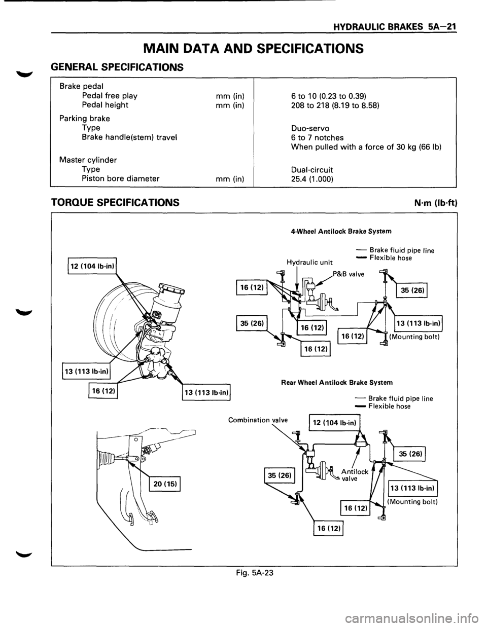
MAIN DATA AND SPECIFICATIONS
GENERAL SPECIFICATIONS
Brake pedal
Pedal
free play
Pedal
height
Parking brake
Type Brake
handle(stem) travel
Master cylinder
Type
Piston bore diameter
TORQUE SPECIFICATIONS
mm (in)
mm (in)
mm (in)
13 (1131b·in)
Fig. 5A-23 6
to 10 (0.23 to 0.39)
208 to 218
(8.19 to 8.58)
Duo-servo
6 to 7 notches
When
pulled with a force of 30 kg (66 lb)
Dual-circuit
25.4 (1.000)
4-Wheel Antilock Brake System
N·m {lb·ft}
-Brake fluid pipe line -Flexible hose
Rear Wheel Antilock Brake System
-Brake fluid pipe line -Flexible hose
Page 342 of 1928
SA-22 HYDRAULIC BRAKES
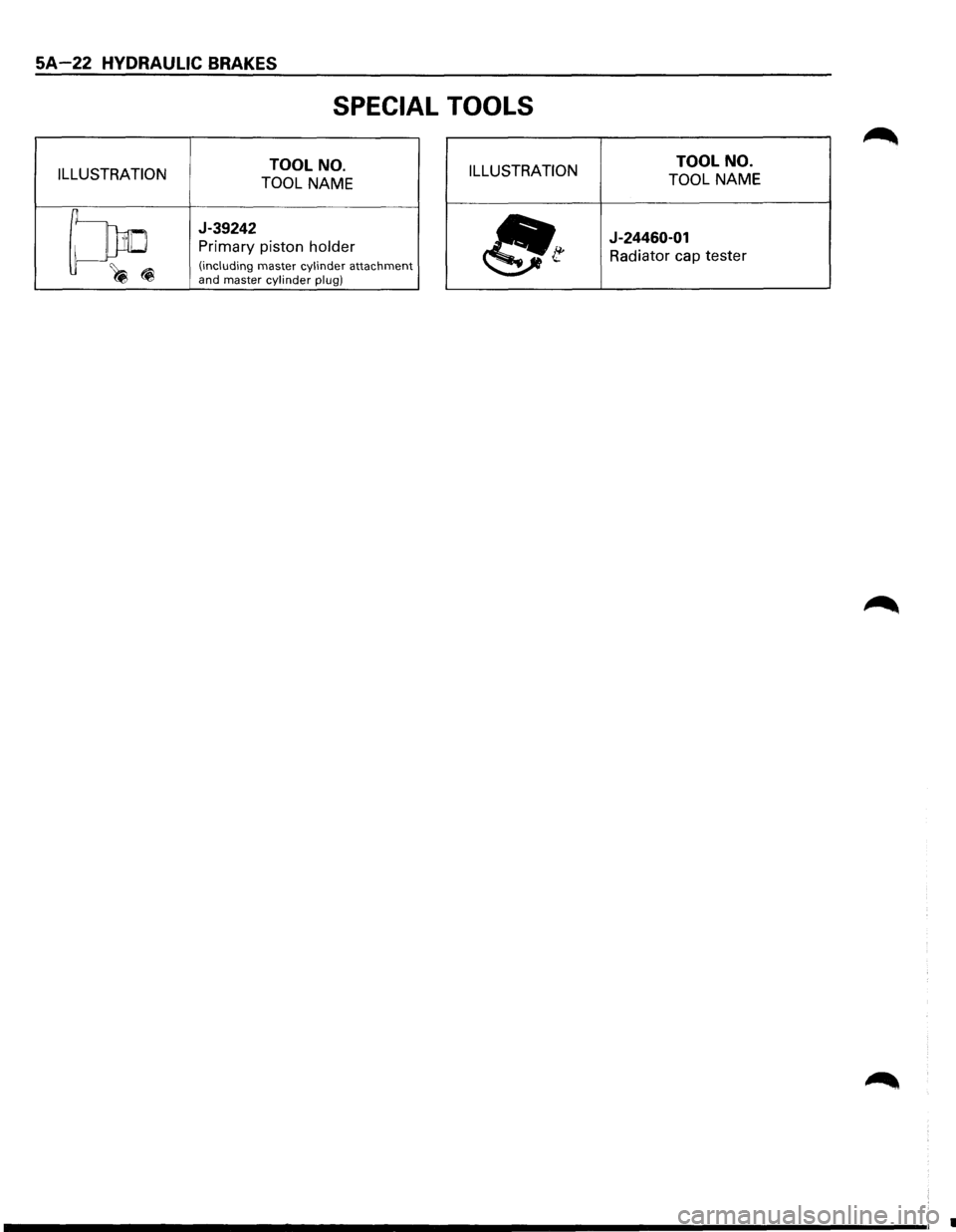
SPECIAL TOOLS
ILLUSTRATION TOOL
NO.
TOOL NAME ILLUSTRATION TOOL
NO.
TOOL NAME
~
J-39242
Primary piston holder
(including master cylinder attachment ~(i and master cylinder plug) ~t
J-24460-01
Radiator cap tester
•
Page 343 of 1928
BRAKE BOOSTER SYSTEM 5A 1-1
SECTION 5A1
BRAKE BOOSTER SYSTEM
W CAUTION:
• Fasteners are an important attaching part in that they could affect performance of vital parts and systems,
and/or could result in major repair expense. They must be replaced with one of the same part number or with
an equivalent part if replacement becomes necessary. Do not use replacement parts of lesser quality or
substitute design. Torque values must be used as specified during reassembly to assure proper retention of
these parts.
CONTENTS
General Description . . . . . . . . . . . . . . . . . . . SA 1-1 Vacuum Booster .................... SA1-6
Diagnosis ..................... See Section SA Main Data and Specifications ........... SA1-6
On-Vehicle Service ................... SA1-2 General Specifications ............... SA1-6
Vacuum Booster Assembly ........... SA1-2 Torque Specifications ................ SA1-6
Exterior Components ................ SA1-4 Special Tools ......................... SA1-7
Unit Repair .......................... SA1-6
GENERAL DESCRIPTION
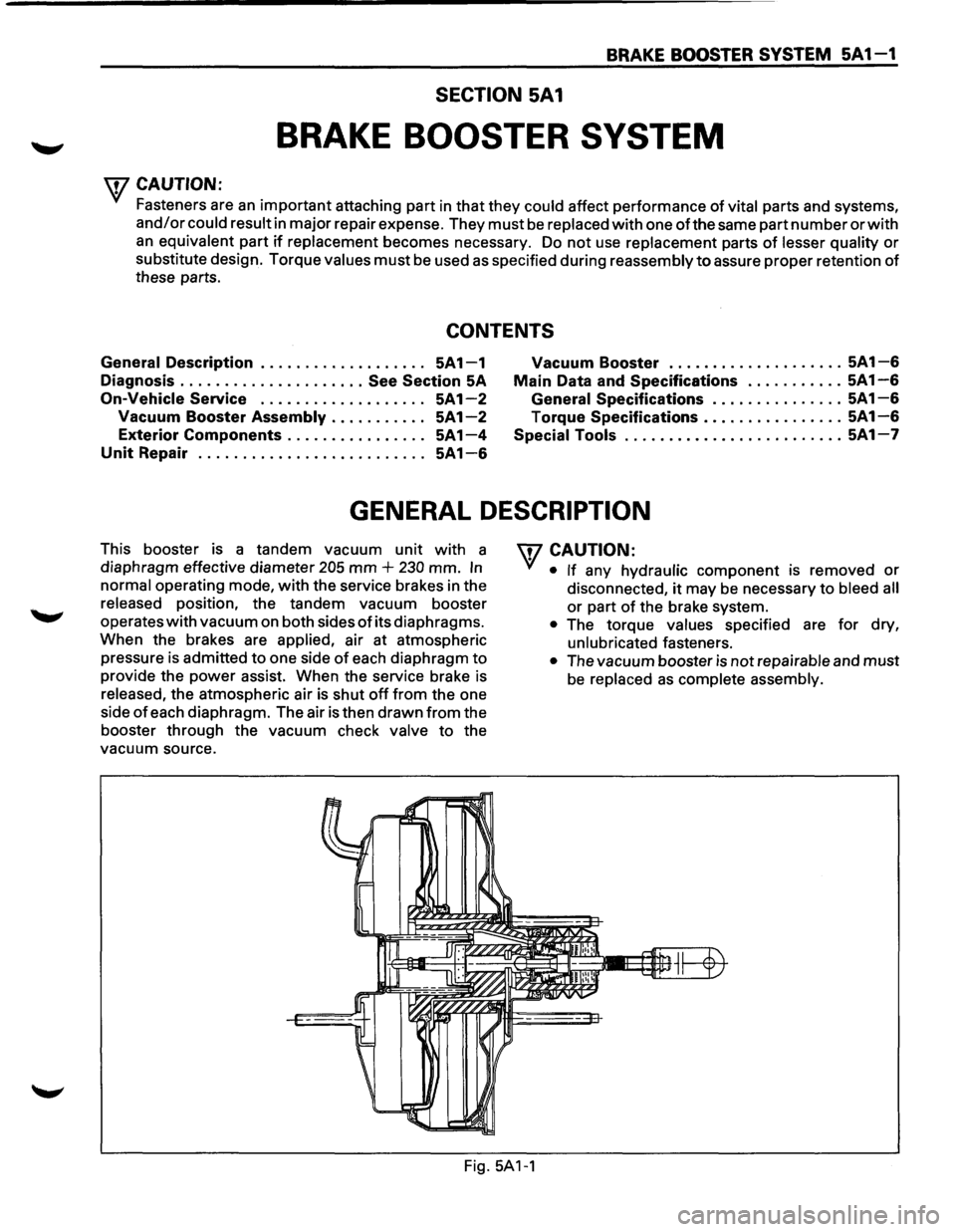
This booster is a tandem vacuum unit with a
diaphragm effective diameter
205 mm + 230 mm. In
normal operating mode, with the service brakes in the
released position, the tandem vacuum booster
operates
with vacuum on both sides of its diaphragms.
When the brakes are
applied, air at atmospheric
pressure is admitted
to one side of each diaphragm to
provide the power assist. When the service brake is
released, the atmospheric air is shut off from the one
side
of each diaphragm. The air is then drawn from the
booster through the vacuum check
valve to the
vacuum source.
W CAUTION:
• If any hydraulic component IS removed or
disconnected, it may be necessary to bleed all
or part of the brake system.
Fig.
5A1-1
• The torque values specified are for dry,
unlubricated fasteners.
• The vacuum booster is not repairable and must
be replaced as complete assembly.
Page 351 of 1928
DISC BRAKES 5A2-1
SECTION 5A2
DISC BRAKES
w CAUTION:
All brake attaching fasteners are an important attaching part in that they could affect performance of vital
parts and systems, and/or could result in major repair expense. They must be replaced with one of the same
part
number or with an equivalent part if replacement becomes necessary. Do not use replacement parts of
lesser quality or substitute design. Torque values must be used as specified during reassembly to assure
proper retention of these parts.
CONTENTS
General Description . . . . . . . . . . . . . . . . . . . . 5A2-1
Operation . . . . . . . . . . . . . . . . . . . . . . . . . . . . 5A2-1
Diagnosis
..................... See Section SA
On-Vehicle Service . . . . . . . . . . . . . . . . . . . . 5A2-2
Front Disc Brakes . . . . . . . . . . . . . . . . . . . . 5A2-2
Brake Pads
Inspection . .
. . . . . . . . . . . . 5A2-2
Brake Pads Replacement . . . . . . . . . . . 5A2-3
Servicing
the Rotor . . . . . . . . . . . . . . . . 5A2-4
Caliper Replacement . .
. . . . . . . . . . . . . 5A2-6
Rebuilding
the Caliper . . . . . . . . . . . . . 5A2-8 Rear
Disc Brakes .................... 5A2-1 0
Brake
Pads Inspection ............. 5A2-1 0
Brake Pads Replacement ........... 5A2-1 0
Servicing the Rotor ............... 5A2-12
Caliper Replacement .............. 5A2-14
Rebuilding the
Caliper ............. 5A2-17
Parking Brakes . . . . . . . . . . . . . . . .
See Section SC
Main Data and Specifications ........... 5A2-19
General Specifications ............... 5A2-19
Torque Specifications
............... 5A2-19
GENERAL DESCRIPTION
The disc brake assembly consists of a caliper, piston,
rotor, pad assembly and
support bracket. The caliper
assembly has a single bore and is mounted to the
support bracket with 2 mounting bolts. The support
bracket allows the caliper to move laterally against the
rotor. The
caliper is a one-piece casting with the
inboard side containing the piston bore. A square cut
rubber
seal is located in a groove in the piston bore
which provides the hydraulic seal between the piston
and the cylinder
wall.
NOTE:
• Replace all components included in repair kits
used
to service this caliper.
• Lubricate rubber parts with clean brake fluid to
ease assembly.
• If any hydraulic component is removed or
disconnected, it may be necessary to bleed all or
part of the brake system.
• Replace pads in axle sets only.
•
The torque values specified are for dry,
unlubricated fasteners.
• Perform service operation a clean bench free
from all mineral oil materials.
OPERATION
Hydraulic pressure, created by applying the brake
pedal, is converted by the caliper to a stopping force.
This force acts
equally against the piston and the
bottom of the caliper bore to move the piston outward
and to move (slide) the caliper inward resulting in a
clamping action on the rotor. This clamping action
forces the
linings against the rotor, creating friction to
stop the vehicle.