horn ISUZU TROOPER 1995 User Guide
[x] Cancel search | Manufacturer: ISUZU, Model Year: 1995, Model line: TROOPER, Model: ISUZU TROOPER 1995Pages: 1928
Page 1296 of 1928
8 - 1 06 CHASSIS ELECTRICAL
TURN SIGNAL LIGHT, HAZARD WARNING LIGHT,
CORNERING LIGHT,
BACKUP LIGHT AND HORN
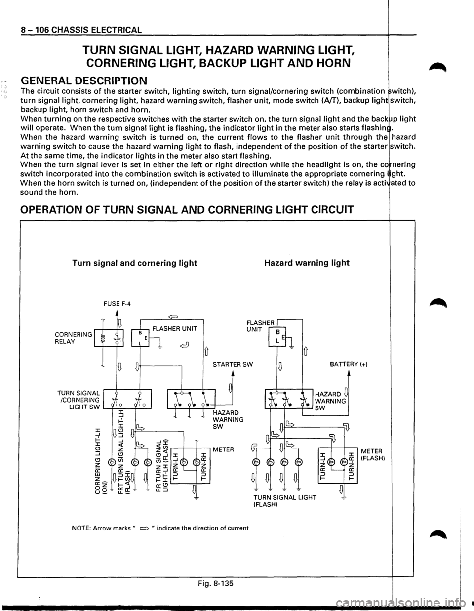
GENERAL DESCRIPTION
The circuit consists of the starter switch, lighting switch, turn signal/cornering switch (combination witch),
turn signal light, cornering light, hazard warning switch, flasher unit, mode switch (A/T), backup light switch,
backup light, horn switch and horn.
When
turning on the respective switches with the starter switch on, the turn signal light and the back p light
will operate. When the turn signal light is flashing, the indicator light in the meter also starts flash in .
When the hazard
warning switch is turned on, the current flows to the flasher unit through the hazard
warning switch to cause the hazard warning light to flash, independent of the position of the starter switch.
At the same time, the indicator lights in the meter also start flashing.
When the
turn signal lever is set in either the left or right direction while the headlight is on, the co nering
switch incorporated
into the combination switch is activated to illuminate the appropriate cornering I ght.
When the horn switch is turned on, (independent
of the position of the starter switch) the relay is acti ated to
sound the horn.
OPERATION OF TURN SIGNAL AND CORNERING LIGHT CIRCUIT
Turn signal and cornering light
CORNERING RELAY
TURN
SIGNAL
/CORNERING FUSE
F-4
~+---------.
Ll G
HT SW L......f-'-=-~--l
STARTER SW
HAZARD
WARNING
sw
NOTE: Arrow marks " ~ " indicate the direction of current
Fig. 8-135
Hazard warning light
D
BATTERY(+)
HAZARD~ WARNING L.f-~'-'----f--' sw
lB
TURN SIGNAL LIGHT
(FLASH)
:z: _J 2: a: :::J 1-
li}
:z: a: 2: a: :::J 1-
~
METER (FLASH)
•
Page 1297 of 1928
 /
CORN")
-n 10' 00 I .... w 0>
(
RELAY:
CORNERING LIGHT
DIODE
RELAY;HORN
\
RELAY
& FUSE
BOX'·.,,
(FL-1, FL-2,
F-31
~.
"",
BATTERY
'
FRT
TURN
SIGNAL,
HAZARD.
WARNING LIGHT
(RH) /
CORNERING LIGHT
(RH) C-31 HORN (HIGH)
( TURN
SIGNAL,
HAZARED
WARNING
INDICATOR LIGHT
(METER)
(
COMBINATION
SW
HAZARD
WARN
IN~
LIGHT
SW
FRT TURN
SIGNAL,
HAZARD
WARNING
LIGHT
(LH)
CORNERING LIGHT
(LH)
LIGHTING
SW
TURN
SIGNAL LIGHT,
/~l/
~/
CORNERING LIGHT SW. RR
TURN
SIGNAL,
HAZARD
WARNING LIGHT (LHI
=·
BACKUP
B-53
LIGHT(LH) "R-7 TRAILER HARNESS
CONNECTOR
FLASHER
UNIT
FUSE
BOX (C-3)
BACKUP LIGHT SW, (MfTI
)g ~ (/) r-0 (") ~ 0
2
(") ::c )> en
en en m rm (") -i :lJ (") )> rQI) I ..a 0 .....
Page 1301 of 1928
CHASSIS ELECTRICAL 8 -111
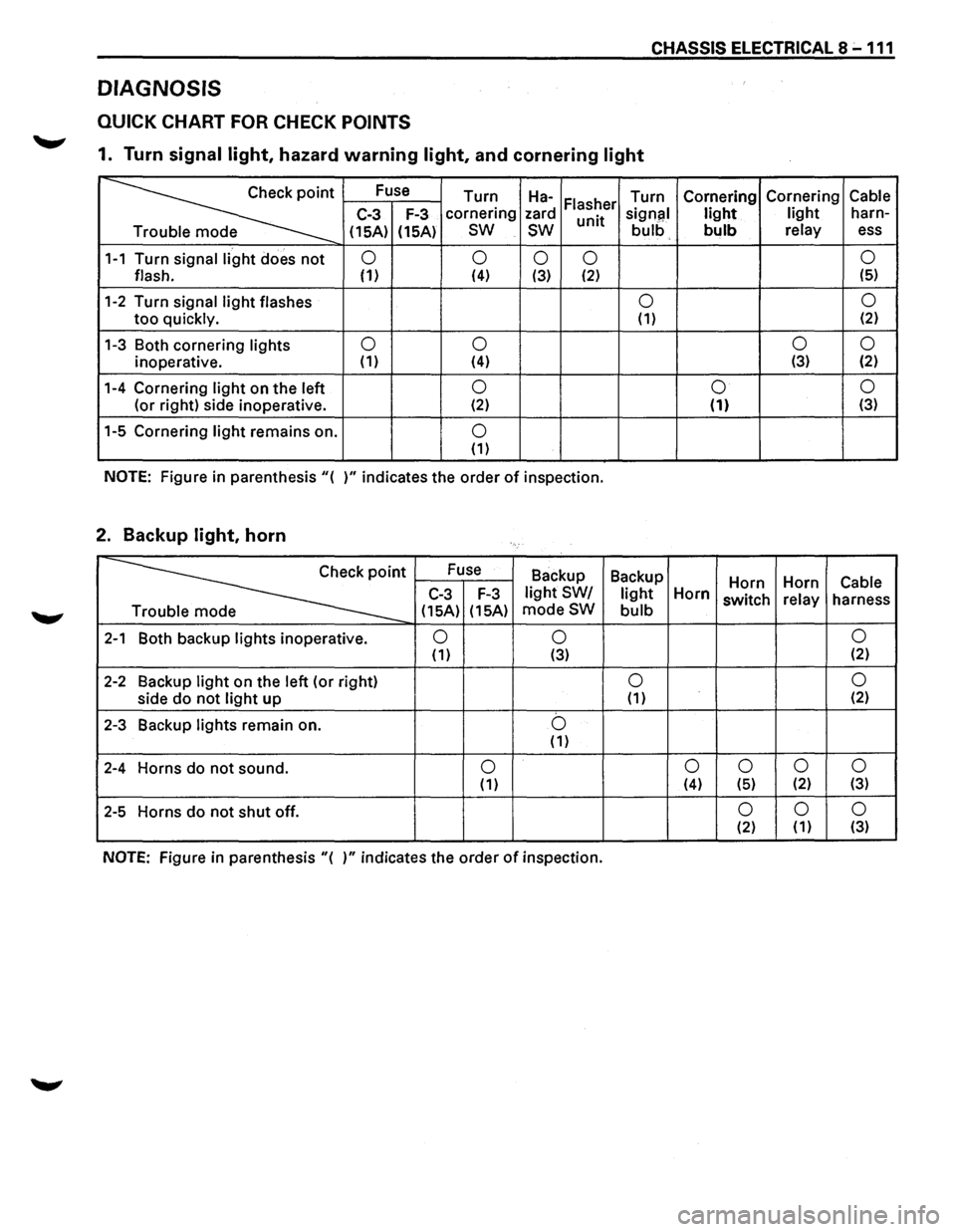
DIAGNOSIS
QUICK CHART FOR CHECK POINTS
1. Turn signal light, hazard warning light, and cornering light
~·
Fuse
Turn Ha-Turn Cornering Cornering Cable Flasher C-3 F-3 cornering
zard
unit signal light light harn-
e (15A)
(15A)
sw
sw bulb bulb relay ess
1-1 Turn signal light does not 0
0 0 0 0
flash. (1) (4) (3) (2) (5)
1-2 Turn
signal light flashes 0 0
too quickly. (1) (2)
1-3 Both
cornering lights 0
0 0
0
inoperative. (1)
(4) (3) (2)
1-4 Cornering light on the left 0 0 0
(or
right) side inoperative. (2) (1) (3)
1-5 Cornering light remains on. 0 (1)
NOTE: Figure in parenthesis"{ )"indicates the order of inspection.
2. Backup light, horn
~·
Fuse
Backup Backup
Horn Horn Cable C-3 F-3 light SW/ light Horn switch relay
harness
e {15A) {15A) modeSW bulb
2-1 Both
backup lights inoperative. 0 0 0 (1) {3) {2)
2-2 Backup light on
the left (or right) 0 0
side do not light up {1) (2)
2-3 Backup lights remain on. b {1)
2-4 Horns do not sound. 0 0
0
0 0 {1) (4) {5) {2) (3)
2-5 Horns do not shut off. 0 0 0 {2) (1) (3)
NOTE: Figure
in parenthesis "{ )" indicates the order of inspection.
Page 1308 of 1928
8-118 CHASSIS ELECTRICAL
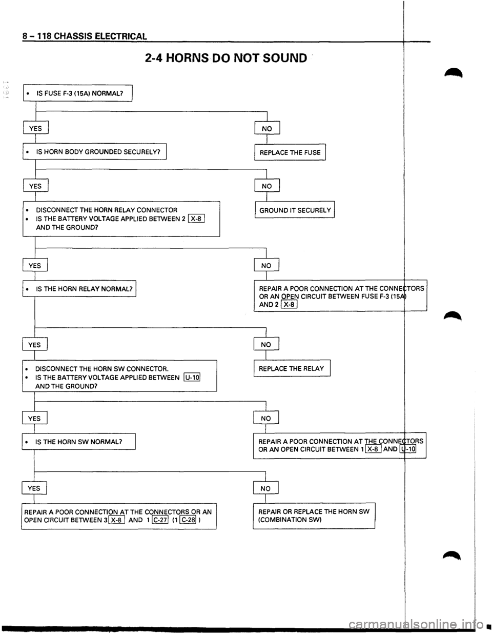
2-4 HORNS DO NOT SOUND
~ ''
• IS FUSE F-3 (15A) NORMAL? I
I
YES j NO I
I
• IS HORN BODY GROUNDED SECURELY? I I REPLACE THE FUSE I
I
YES I NO I
I
• DISCONNECT THE HORN RELAY CONNECTOR GROUND IT SECURELy I
• IS THE BATIERY VOLTAGE APPLIED BETWEEN 2 I X-8 I
AND THE GROUND?
I
YES I NO I
I
• IS THE HORN RELAY NORMAL? I REPAIR A POOR CONNECTION AT THE CONNE TORS OR AN OPEN CIRCUIT BETWEEN FUSE F-3 (15.4
AND 21 X-81
~
I
YES NO I
I
• DISCONNECT THE HORN SW CONNECTOR . REPLACE THE RELAY J
• IS THE BATIERY VOLTAGE APPLIED BETWEEN lu-101
AND THE GROUND?
I
YES I NO J
I
• IS THE HORN SW NORMAL? I REPAIR A POOR CONNECTION AT THE CONN~ ~RS OR AN OPEN CIRCUIT BETWEEN 11 X-8 I AND ~ 0
I
YES / NO /
I
REPAIR A POOR CONNECTION AT THE CONNECTORS OR AN REPAIR OR REPLACE THE HORN SW
OPEN CIRCUIT BETWEEN 31 X-8 I AND 1IC-27l (11 C-281) (COMBINATION SW)
~
•
Page 1309 of 1928
CHASSIS ELECTRICAL 8-119
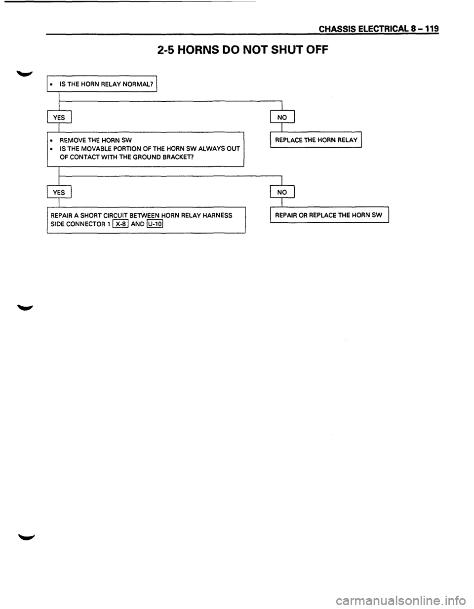
2-5 HORNS DO NOT SHUT OFF
• IS THE HORN RELAY NORMAL? I
I
I I
YES [ NO l
I
I
• REMOVE THE HORN SW I REPLACE THE HORN RELAY I
• IS THE MOVABLE PORTION OF THE HORN SW ALWAYS OUT
OF CONTACT WITH THE GROUND BRACKET?
I
I I
YES I r NO l
l I
REPAIR A SHORT CIRCUIT BETWEEN HORN RELAY HARNESS I REPAIR OR REPLACE THE HORN SW I
SIDE coNNECTOR 1 I x-sl AND lu-1ol
Page 1314 of 1928
8-124 CHASSIS ELECTRICAL
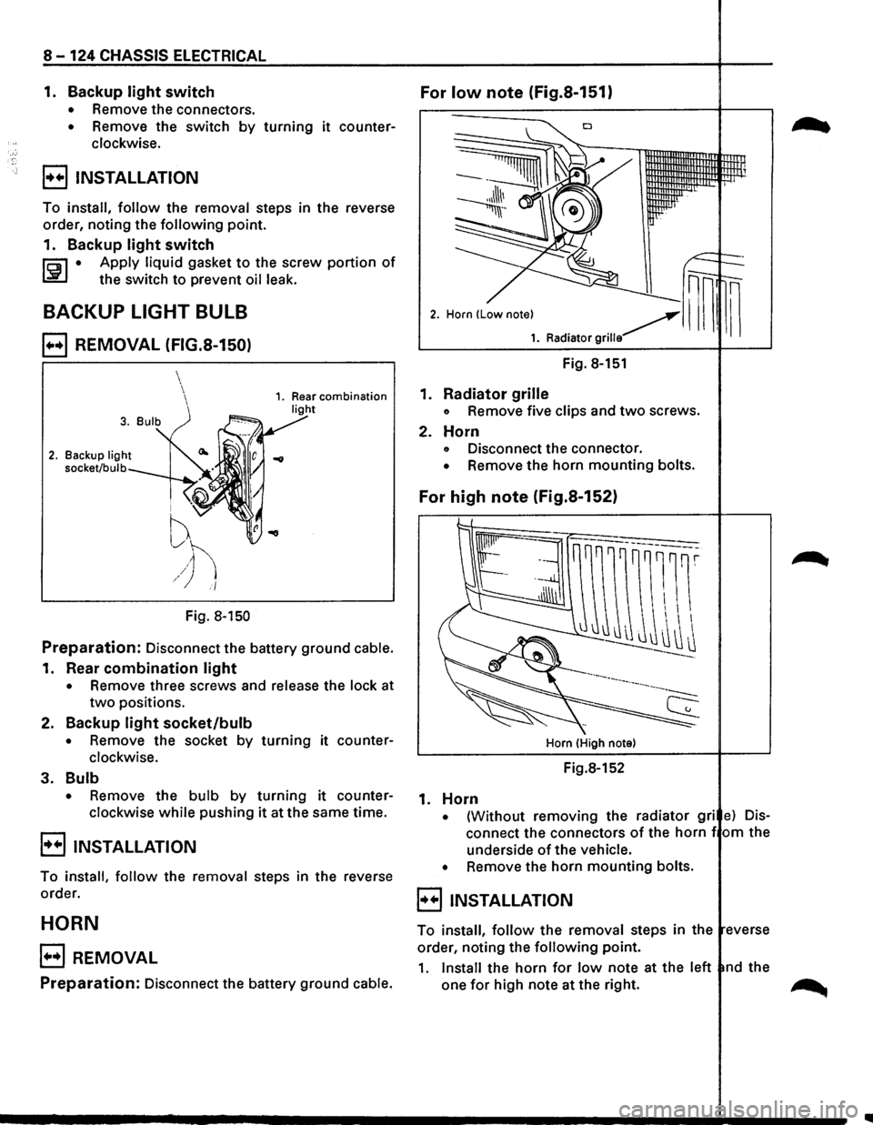
1. Backup light switch For low note (Fig.S-151)
• Remove the connectors.
• Remove the switch by turning it counter
clockwise.
B INSTALLATION
To install, follow the removal steps in the reverse
order,
noting the following point.
1.
Backup light switch
li:i1 • Apply liquid gasket to the screw portion of
~ the switch to prevent oil leak.
BACKUP LIGHT BULB
B REMOVAL (FIG.S-150)
2. Backup light
socket/bulb
i ''V
f
~h /) i/
Fig. 8-150
Preparation: Disconnect the battery ground cable.
1. Rear combination light
• Remove three screws and release the lock at
two positions.
2.
Backup light socket/bulb
• Remove the socket by turning it counter
clockwise.
3. Bulb
• Remove the bulb by turning it counter
clockwise
while pushing it at the same time.
B INSTALLATION
To install, follow the removal steps in the reverse
order.
HORN
B REMOVAL
Preparation: Disconnect the battery ground cable.
Fig. 8-151
1.
Radiator grille
o Remove five clips and two screws.
2. Horn
o Disconnect the connector.
• Remove the horn mounting bolts.
For high note (Fig.S-152)
Horn (High note)
Fig.8-152
1. Horn
• {Without removing the radiator gri e) Dis
connect the connectors of the horn f om the
underside
of the vehicle.
•
Remove the horn mounting bolts.
8 INSTALLATION
To install, follow the removal steps in the everse
order, noting the
following point.
1. Install the horn for low note at the left nd the
one
for high note at the right. ~
Page 1315 of 1928
HORN SWITCH
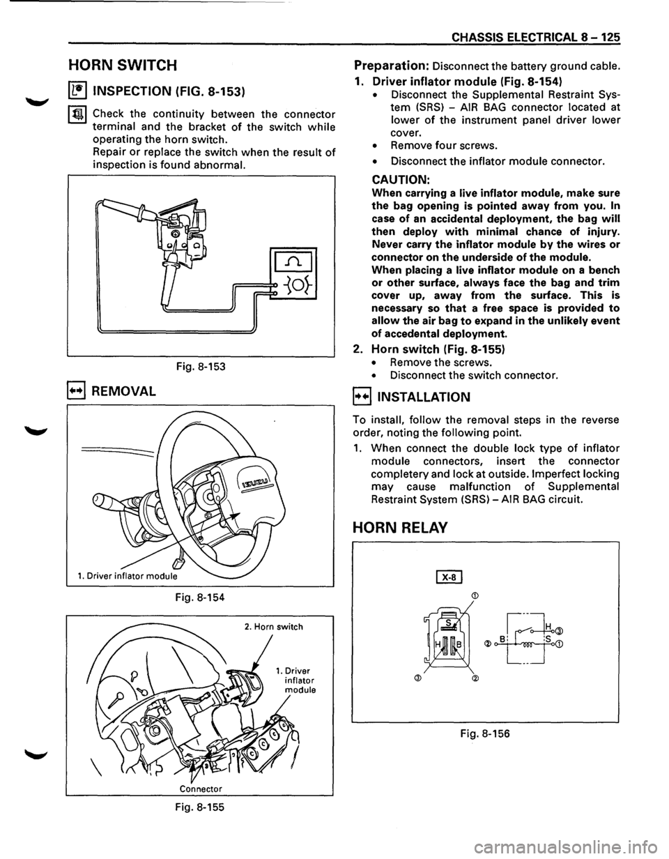
~ INSPECTION (FIG. 8-153)
~~~ Check the continuity between the connector
terminal and the bracket of the switch while
operating the horn switch.
Repair
or replace the switch when the result of
inspection is found abnormal.
Fig. 8-153
B REMOVAL
Fig. 8-154
Connector
Fig. 8-155
CHASSIS ELECTRICAL 8-125
Preparation: Disconnect the battery ground cable.
1. Driver inflator module (Fig. 8-154)
• Disconnect the Supplemental Restraint Sys
tem (SRS) -AIR BAG connector located at
lower of the instrument panel driver lower
cover.
• Remove four screws.
• Disconnect the inflator module connector.
CAUTION:
When carrying a live inflator module, make sure
the bag opening is pointed away from you. In
case of an accidental deployment, the bag will
then deploy with minimal chance of injury.
Never carry
the inflator module by the wires or
connector on the underside of the module.
When placing a live inflator module on a bench
or other surface, always face the bag and trim
cover up, away from the surface. This is
necessary so
that a free space is provided to
allow the air bag to expand in the unlikely event
of accedental deployment.
2. Horn switch (Fig. 8-155)
• Remove the screws.
• Disconnect the switch connector.
l·u·IINSTALLATION
To install, follow the removal steps in the reverse
order, noting the
following point.
1. When connect the double lock type of inflator
module connectors, insert the connector
completery and lock at outside. Imperfect locking
may cause malfunction of Supplemental
Restraint System (SRS)-AIR BAG circuit.
HORN RELAY
Page 1460 of 1928
8-270 CHASSIS ELECTRICAL
ANTI-THEFT SYSTEM
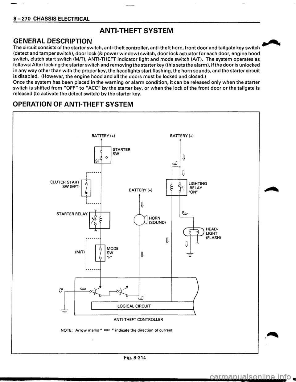
GENERAL DESCRIPTION .......
The circuit consists ofthe starter switch, anti-theft controller, anti-theft horn, front door and tailgate key switch
(detect and tamper switch),
door lock (&power window) switch, door lock actuator for each door, engine hood
switch, clutch start switch (MfT),
ANTI-THEFT indicator light and mode switch (AfT). The system operates as
follows: After locking the starter switch and removing the starter key (this sets the alarm),
ifthe door is unlocked
in any
way other than with the proper key, the headlights start flashing, the horn sounds, and the starter circuit
is disabled. (However,
the engine hood and all the doors must be locked and closed.)
Once the system has been placed in the warning or alarm condition, it can be released only when the starter
switch is shifted
from "OFF" to "ACC" by the starter key, or when the lock of the front door or the tailgate is
released (to activate the detect switch)
by the starter key.
OPERATION OF ANTI-THEFT SYSTEM
'
'
CLUTCH START m
SW(M/Tiw
' '
'
BATIERY(+)
0 ST
STARTER sw
BATIERY(+)
L------
STARTER RELAY
' ' (MIT):
'
'
'
HORN
(SOUND)
ANTI-THEFT CONTROLLER
BATIERY(+)
LIGHTING
RELAY
"ON"
HEADLIGHT (FLASH)
NOTE: Arrow marks u ~ u indicate the direction of current
Fig. 8-314
•
Page 1461 of 1928
'"T1 !fl' co I w _. (11
I i i, ~
(
RR
DOOR
LOCK
ACTUATOR
{RHJ
FRT
DOOR
LOCK
SW
(RH
FRT
DOOR
KEY
SW,
(RH),
( ANTI-THEFT
CONTROLLER
RR
DOOR
SW
(RHJ
-------
FRT
DOOR
SW,
(RH)
.~""··
\
/;'~
~
"'··
FRT
DOOR
LOCK
ACTUATOR
(RH)
'-, ..,/j.
',
H-14
'L
y'JIJ.
"·,
H-15"
82
ANTI-THEFT
HORN~-20
"-,
-
RELAY
& FUSE
BOX
~
{FL-1,
FL-2,
F-3)
~
RELAY:
STARTER BATTERY
X::
H-41 B-39 DIODE
B-40 DIODE
B-43 DIODE FUSE
BOX MODESW
TRANSMISSION ,
TAILGATE
LOCK
ACTUATOR
TAILGATE
KEY
SW
TAILGATESW
FRT
DOOR
LOCK
&
/'POWER
WINDOW
SW
H-37 H-38 RRDOOR SW,(LH)
.
RR
DOOR
LOCK
-~ACTUATOR
{LHJ
FRT
DOOR
KEY
SW,
{LH)
-H-28,
H-29
FRT
DOOR
LOCK
ACTUA
TOR
(LH)
(
;g ~ C/) 5 C') ~ 0 z
n :X: ~ (/) 0 m rm ~ n ):a r-0) I N ..... -
Page 1465 of 1928
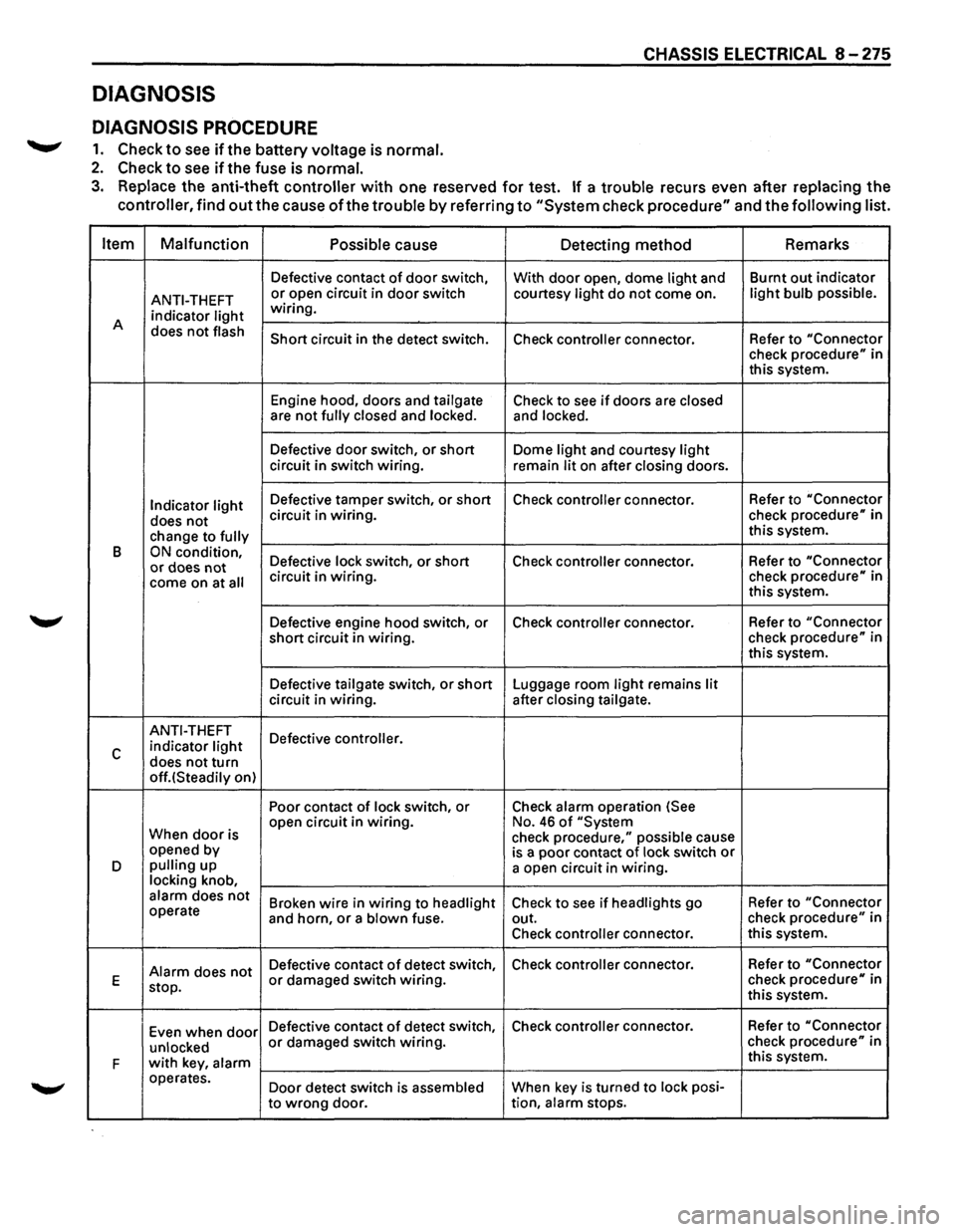
DIAGNOSIS
DIAGNOSIS PROCEDURE
.......,. 1. Check to see ifthe battery voltage is normal.
2. Check to see if the fuse is normal.
CHASSIS ELECTRICAL 8 -275
3. Replace the anti-theft controller with one reserved for test. If a trouble recurs even after replacing the
controller, find
out the cause of the trouble by referring to "System check procedure" and the following list.
Item Malfunction
Possible
cause Detecting method Remarks
Defective
contact of door switch,
With door open, dome light and Burnt
out indicator
ANTI-THEFT or open circuit in door switch courtesy light do not come on. light bulb possible.
indicator light wiring.
A does
not flash Short circuit in the detect switch.
Check controller connector. Refer to "Connector check procedure" in
this system.
Engine hood, doors and
tailgate Check to see if doors are closed are not fully closed and locked. and locked.
Defective door switch, or short Dome light and courtesy light circuit in switch wiring.
remain lit on after closing doors.
Indicator light Defective tamper switch, or short Check controller connector. Refer
to "Connector
does not circuit in wiring. check procedure" in
change to
fully this system.
B
ON condition, Defective lock switch, or short Check controller connector. Refer
to "Connector or does not come on at all circuit in wiring. check procedure" in
this system.
Defective engine hood switch, or Check
controller connector. Refer
to "Connector
short circuit in wiring. check
procedure" in
this system.
Defective
tailgate switch, or short Luggage room light remains lit circuit in wiring. after closing tailgate.
ANTI-THEFT
Defective controller.
c indicator light
does not turn off.(Steadily on) Poor contact
of lock switch, or Check alarm operation (See
When
door is open
circuit in wiring. No. 46 of "System
check procedure," possible cause
opened by
is a poor contact of lock switch or D pulling up
a open circuit in wiring. locking knob, alarm does not Broken wire in wiring to headlight Check to see if headlights go Refer
to "Connector operate
and horn, or a blown fuse. out. check procedure" in
Check
controller connector. this
system.
Alarm does not Defective contact of detect switch, Check controller connector.
Refer to "Connector
E
stop. or damaged switch wiring. check procedure" in
this system.
Even when
door Defective contact of detect switch, Check controller connector. Refer
to "Connector
unlocked
or damaged switch wiring. check procedure" in
F
with key, alarm this system.
operates. Door detect switch is
assembled When key is turned to lock posi-
to
wrong door. tion, alarm stops.