horn ISUZU TROOPER 1995 Workshop Manual
[x] Cancel search | Manufacturer: ISUZU, Model Year: 1995, Model line: TROOPER, Model: ISUZU TROOPER 1995Pages: 1928
Page 215 of 1928
SUPPLEMENTAL RESTRAINT SYSTEM (SRS) STEERING WHEEL & COLUMN 3F4-5
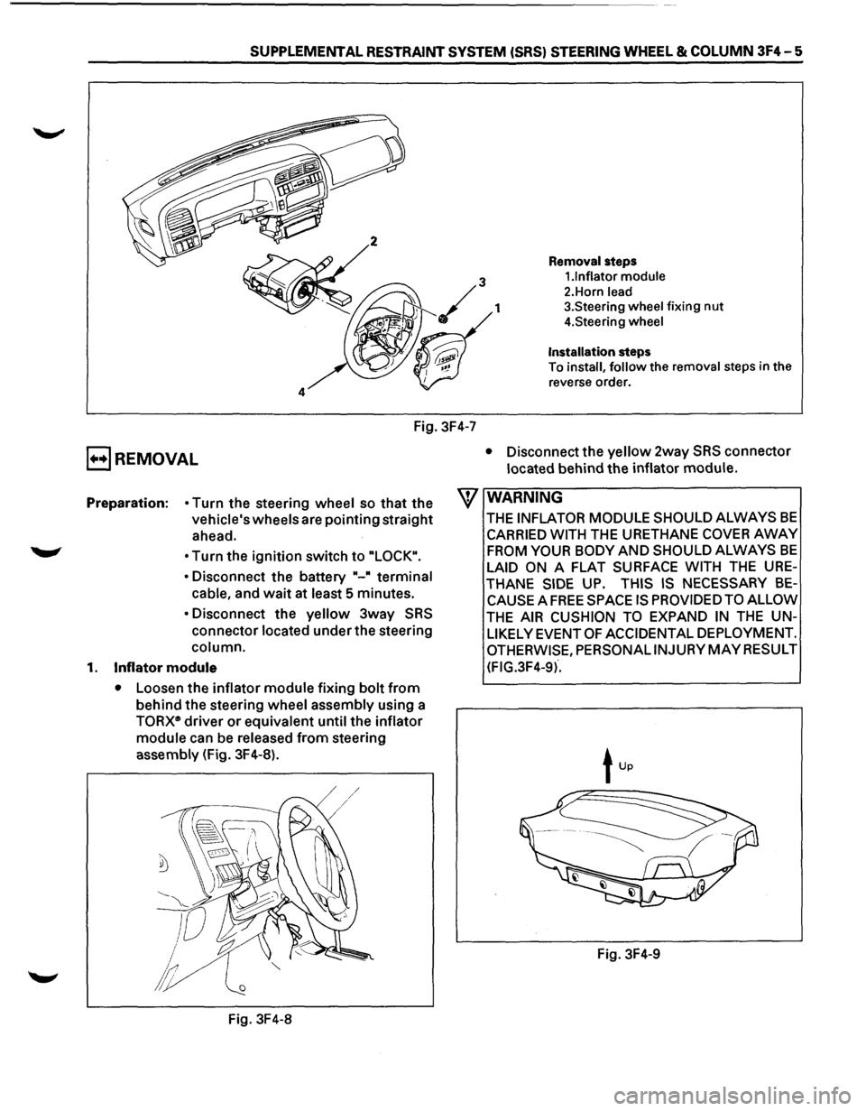
Removal steps
1.1nflator module
2.Horn lead
1 3.Steering wheel fixing nut
4.Steering wheel
Installation steps
To
install, follow the removal steps in the
reverse order.
Fig. 3F4-7
E) REMOVAL
Preparation: • Turn the steering wheel so that the
vehicle's wheels are
pointing straight
ahead.
• Turn the ignition switch to "LOCK".
•
Disconnect the battery "-• terminal
cable, and
wait at least 5 minutes.
• Disconnect the yellow 3way SRS
connector located under the steering
column.
1. Inflator module
• Loosen the inflator module fixing bolt from
behind the steering wheel assembly using a
TORXe driver or equivalent until the inflator
module can be released from steering
assembly (Fig. 3F4-8).
Fig. 3F4-8
• Disconnect the yellow 2way SRS connector
located behind
the inflator module.
W WARNING
THE INFLATOR MODULE SHOULD ALWAYS BE
CARRIED WITH THE URETHANE COVER AWAY
FROM YOUR BODY AND SHOULD ALWAYS BE
LAID ON A FLAT SURFACE WITH THE URE
THANE SIDE UP. THIS IS NECESSARY BE
CAUSE A FREE SPACE IS PROVIDED TO ALLOW
THE AIR CUSHION TO EXPAND IN THE UN
LIKELY EVENT
OF ACCIDENTAL DEPLOYMENT.
OTHERWISE, PERSONAL INJURY MAY RESULT
(FIG.3F4-9l".
Fig. 3F4-9
Page 216 of 1928
3F4-6 SUPPLEMENTAL RESTRAINT SYSTEM ISRSI STEERING WHEEL & COLUMN
2. Horn lead
3. Steering wheel fixing nut
4. Steering wheel
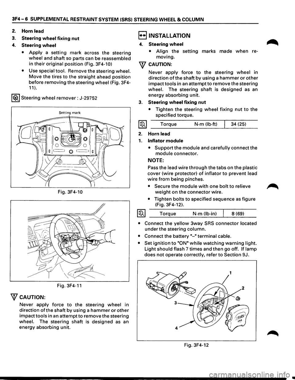
• Apply a setting mark across the steering
wheel and shaft so parts can be reassembled
in
their original position (Fig. 3F4-10)
•
Use special tool. Remove the steering wheel.
Move the tires to the straight ahead position
before removing
the steering wheel (Fig. 3F4-
11 ).
1®.1 Steering wheel remover: J-29752
Setting mark
Fig. 3F4-10
Fig. 3F4-11
"fCAUTION:
Never apply force to the steering wheel in
direction
ofthe shaft by using a hammer or other
impacttools in an attemptto remove the steering
wheel. The steering shaft is designed as an
energy absorbing unit.
B INSTALLATION
4. Steering wheel
• Align the setting marks made when re
moving.
"f CAUTION:
3.
~
2.
1.
~
Never apply force to the steering wheel in
direction
of the shaft by using a hammer or other
impacttools in an attemptto remove the steering
wheel. The steering shaft is designed as an
energy absorbing unit.
Steering wheel fixing nut
• Tighten the steering wheel fixing nut to the
specified torque.
Torque
N-m (lb·ft) 34 (25)
Horn
lead
Inflator module
• Support the module and carefully connect the
module connector.
NOTE:
Pass the lead wire through the tabs on the plastic
cover (wire protector) of inflator to prevent lead
wire from being pinches.
• Secure the module with one bolt to relieve
weight on the connector wire.
• Tighten bolts to specified sequence as figure
(Fig. 3F4-12).
Torque
N·m (lb-in) 8 (69)
• Connect the yellow 3way SRS connector located
under the steering column.
• Connect the battery"-" terminal cable.
• Set ignition to "ON• while watching warning light.
Light
should flash 7 times and then go off. If lamp
does not operate correctly, refer to Section 9J.
Fig. 3F4-12
~
•
Page 1191 of 1928

CHASSIS ELECTRICAL 8-1
·SECTION 8
CHASSIS ELECTRICAL
'\f CAUTION: .
When fasteners are removed, always reinstall them at the same location from which they were removed.
If a fastener needs to be replaced, use the correct part number fastener for that application. If the correct
part number fastener is not
available, a fastener of equal size and strength (or stronger) may be used.
Fasteners that are not reused, and those requiring thread
locking compound, will be called out. The correct
torque
values must be used when installing fasteners that require it. If the above conditions are not
followed, parts or system damage could result.
CONTENTS
General Information .................................... 8-2
Notes for Working on Electrical
Items .................................................... 8-2
Symbols and Abbreviations ................. 8-8
Symbols ............................................ 8-8
Abbreviations ................................... 8-9
Parts for Electrical Circuit ..................... 8-10
Wiring ............................................... 8-10
Fuse .................................................. 8-11
Fusible Link ....................................... 8-12
Circuit Breaker ................................... 8-12
Relay ................................................. 8-12
Relay Specifications and
Configurations ................................ 8-13
Diode ................................................. 8-14
Connector ......................................... 8-15
Reading the Circuit Diagram ................ 8-17
Main Data and Specifications .................... 8-19
Bulb Specifications ................................ 8-19
Fuse,
Fusible Link and
Circuit Breaker Location ..................... 8-21
Fuse
Block Circuit .................................. 8-22
Reference Table of Fuse, Fusible
Link and Circuit Breaker ..................... 8-23
Relay Location ....................................... 8-27
Diode Location .......................................
8-28
Grounding Point .................................... 8-29
Reference Table ................................ 8-29
Location ............................................ 8-31
Cable Harness Routing .......................... 8-34
System Repair .............................................. 8-38
Start and Charging ................................ 8-38
Engine Control Module
(ECM) ................................................... 8-47
Headlight and Fog Light ........................ 8-58
Front Side Marker Light, Parking Light,
Taillight, License Plate Light and
Illumination Light .............................. 8-76
Stoplight and Rear Defogger .............. 8-92
Turn Signal Light, Hazard
Warning
Light, Cornering Light,
Backup
Light and Horn ..................... 8-106
Dome Light, Luggage room Light,
Courtesy Light, Map Light,
Seat Belt Switch and
Warning Buzzer ................................. 8-128
Power Door Lock ................................. 8-142
Power
Window .................................... 8-156
Cruise
Control ...................................... 8-172
Anti-Lock Brake
System (ABS) ........... 8-178
Rear
Wheel Anti-Lock Brake
System (RWAL) ................................. 8-185
Transmission
Control Module
(TCM) ................................................. 8-192
A/T Shift Lock ...................................... 8-200
Windshield
Wiper/Washer and
Rear
Wiper/Washer .......................... 8-205
Headlight wiper /washer ..................... 8-232
Audio, Auto Antenna,
Cigarette
Lighter and digital clock ... 8-246
Power Door Mirror ............................... 8-254
Anti-theft System ................................ 8-270
Meter and Warning/Indicator Light ... 8-288
A/T Shift Indicator ............................... 8-336
Heater and
Air Conditioning ............... 8-340
Sun
Roof ............................................... 8-346
Power Seat ........................................... 8-360
Seat
Heater .......................................... 8-37 4
Supplemental Restraint
System (SRS) -AIR BAG ................... 8-382
Page 1198 of 1928
8-8 CHASSIS ELECTRICAL
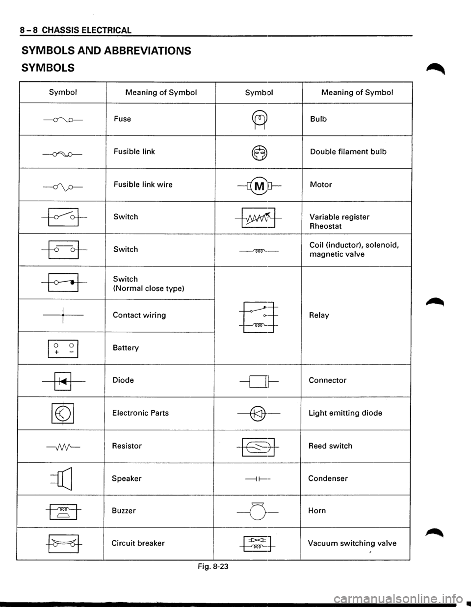
SYMBOLS AND ABBREVIATIONS
SYMBOLS
Symbol Meaning of Symbol
~ Fuse
~ Fusible link
----if\p-Fusible link wire
~ Switch
~ Switch
-a-
Switch
(Normal close type)
j Contact wiring I
[I] -I
Battery
~
Diode
~
Electronic Parts
--Nt-Resistor
=Q] Speaker
1~1 Buzzer I
-EJ-Circuit breaker
I Symb•:>l Meaning of Symbol
~
Bulb
~ Double filament bulb
-r@[}-Motor
~j-Variable register
Rheostat
Coil (inductor), solenoid,
~-magnetic valve I
§
Relay
-or-Connector
----@-Light emitting diode
~8-
Reed switch
---11----Condenser
I -o-Horn
~t Vacuum switching valve I
Fig. 8-23
•
Page 1203 of 1928
CHASSIS ELECTRICAL 8-13
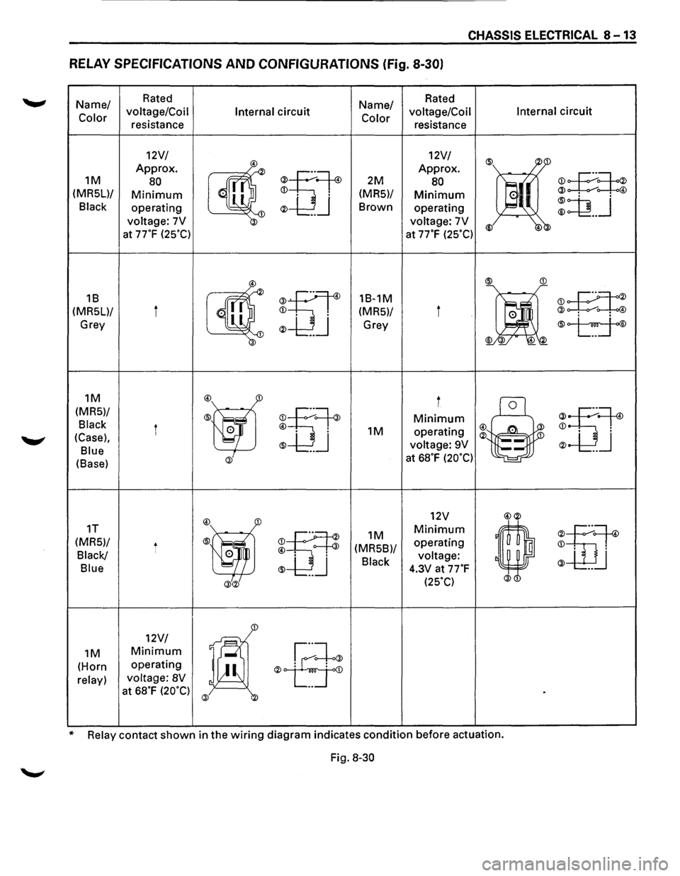
RELAY SPECIFICATIONS AND CONFIGURATIONS (Fig. 8-30)
Name/ Rated Name/ Rated
Color voltage/Coil
Internal circuit Color voltage/Coil Internal circuit
resistance resistance
12V/ 12V/
® ~1 Approx.
~
®u~
Approx.
~£:=!:~ 1M 80 2M 80
a(( (MRSL)/ Minimum
operating ® ... J Brown operating ::Q __ j
voltage: 7V voltage: 7V ® 4 at 77°F (2S°C) at 77"F (2SOC)
~
®
®tiT
18-1M
•
:E:t:
(MR5)/ i @ . . @
Grey Grey ®~ 4
1M
:@ff
i
®~
(MRS)/
rou~ Minimum
u~ Black i 0 @ . 1M operating ~ : 4
(Case), ® ... J ® 1
® J Blue voltage:
9V
(Base) @ at 68°F (20°C)
:@j
12V @®
1T
m
1M Minimum
'
m~
(MRS)/ t (MRSB)/ operating ~ : Black/ ' 0 @ voltage: @ u
Blue ® 4.3V at 77°F
@® (2SOC)
1
12V/
1@ .ff
1M Minimum
(Horn operating ®
at 68°F (20°C) @ .
* Relay contact shown in the wiring diagram indicates condition before actuation.
Fig.
8-30
Page 1211 of 1928
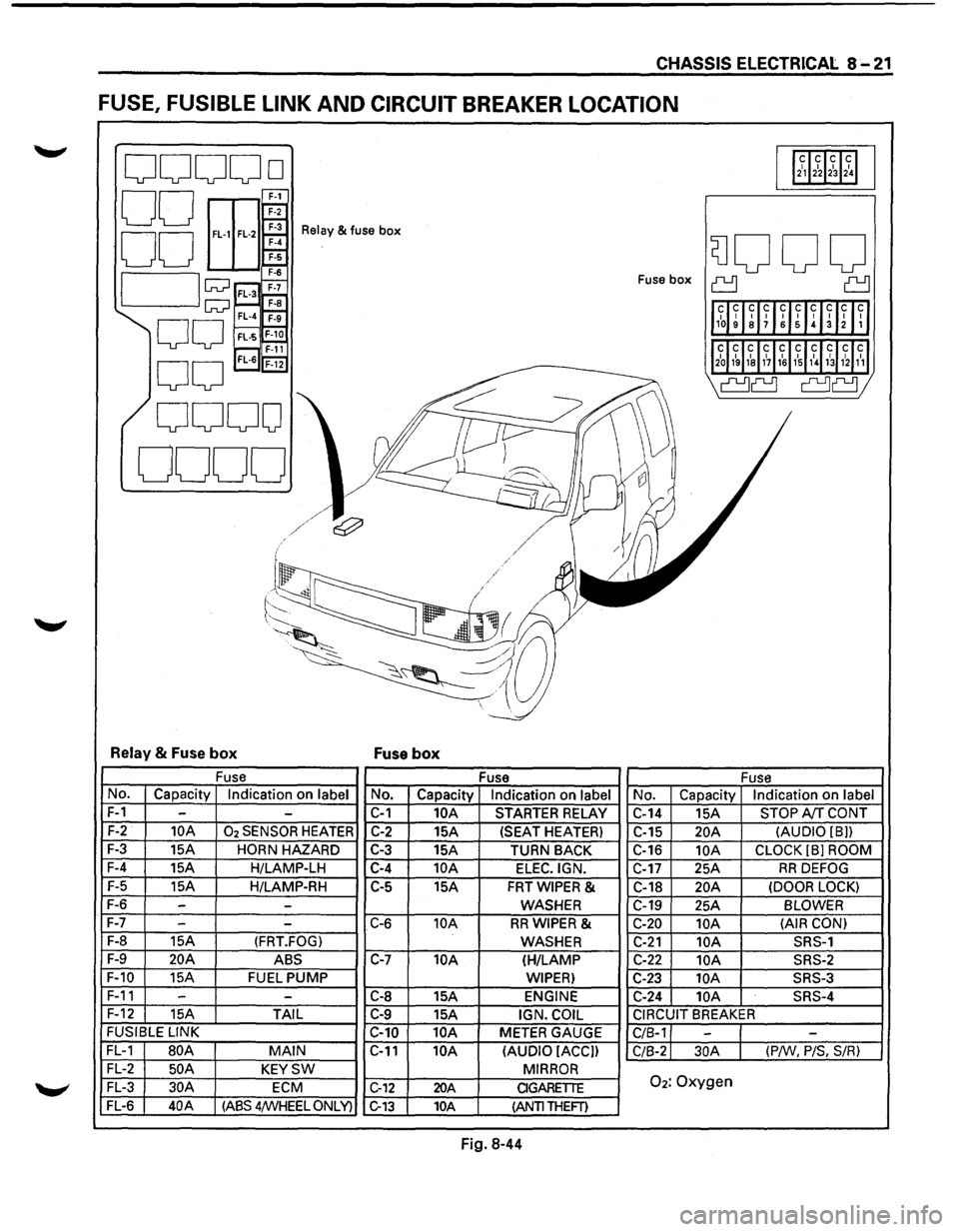
CHASSIS ELECTRICAL 8-21
FUSE, FUSIBLE LINK AND CIRCUIT BREAKER LOCATION
ooooo 112~12~1~1~1
00 E
EEr 00 ~
Relay & fuse box
SJOOO 7-6
I lw ;;::;~ Fuse box ~ ~
1l1~~ ~lff~UIH~Inll
w~ F-a FL-4 ~
00 FL·S~ r---, F-11 'l2~J1~ 1~1&11~11~1,\l~31hl1~1
0
0
FL-6 'F-i2
I' ~
\a~ a~;
0000
0000
I ~
l/
~
j
~/~/ e:;?' v II I / / .I / /
('-/ .
~~
-~-~;,a~ ~~ --.:_
~~~~ -
Relay & Fuse box Fuse box
Fuse
Fuse Fuse
No. Capacity Indication on label No. Capacity Indication on label No. Capacity Indication on label
F-1 --C-1 10A STARTER RELAY
C-14 15A STOP A!f CONT
F-2 10A 02 SENSOR HEATER C-2 15A (SEAT HEATER)
C-15 20A (AUDIO [8))
F-3
15A HORN HAZARD C-3 15A
TURN BACK C-16 10A CLOCK (8] ROOM
F-4
15A H/LAMP-LH C-4 10A ELEC.IGN. C-17 25A RR DEFOG
F-5
15A H/LAMP-RH C-5
15A FRTWIPER & C-18 20A (DOOR LOCK)
F-6 --WASHER C-19
25A BLOWER
F-7
- -C-6 10A RRWIPER & C-20 10A (AIR
CON)
F-8
15A (FRT.FOG) WASHER C-21 10A SRS-1
F-9 20A ABS C-7 10A (H/LAMP C-22 10A SRS-2
F-10
15A FUEL PUMP WIPER) C-23 lOA SRS-3
F-11 -
-C-8 15A ENGINE C-24 10A SRS-4
F-12
15A TAIL C-9 15A IGN. COIL CIRCUIT BREAKER
FUSIBLE
LINK
C-10 10A METER GAUGE
C/8-1 --FL-1 80A MAIN C-11 10A
(AUDIO IACC])
C/8-2 30A (P/W, P/S, S/R)
FL-2 50 A KEYSW MIRROR
FL-3 30A ECM C-12 20A CIGARETTE 02: Oxygen
FL-6 40A (ASS 4/WHEEL ONLY) C-13 10A (ANTI THEFT)
Fig. 8-44
Page 1212 of 1928
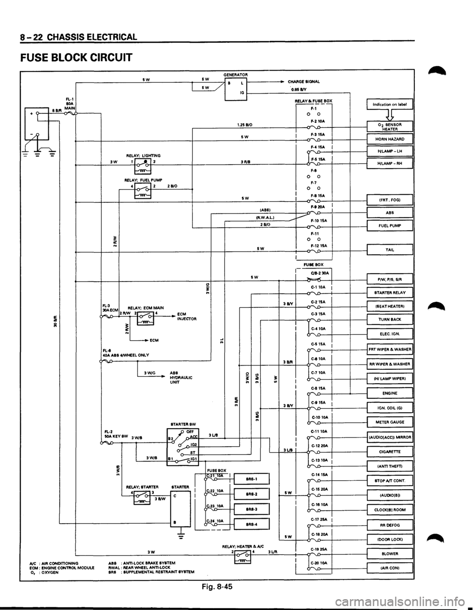
8-22 CHASSIS ELECTRICAL
FUSE BLOCK CIRCUIT
GENERATOR -------------------~s~w~------------~~s~w~--~~~~ r- / B L 1------CHARGE SIGNAL &W _/
FL-1 80A .-----, B 11.'1 MAIN
+ Lt--
l£h
~----/ IG~----------~O~.$~B/V~-----------,
3W REL~HT1NG 1J ---'"~L 3
RELA~PUMP 4 1...---. 12 2 B/0
1.25 B/0
SW
3RJ8
5W
~~~·~ F-1 0 0 F-2 10A
I F-315A
F-8
0 0 F-7 0 0 F-81SA
F-920A
9;nlaool
I
Oz SENSOR HEATER
HORN HAZARD
H/LAMP-LH
H/LAMP-RH
(FRT. FOG)
lABS) -I ABS
I ,--------__:<;;:R·.:.:W.::..Acc·L;;:-1 ____ ----Jv F-10 1SA 2 810
I
~ECM RELAY; ECM MAIN ¢~,...,..J>--+2'-'RIW~_::2~1-o.....-<:>-f-·4.:._ __ _. ~J~CTOR
L...-_.ECM
FL-t 40A ABS 4/WHEEL ONLY
"
.... ...
SW
5W
3 8IY
F-11 0 0 F-1215A
~------' FUSE BOX
CIB-2 30A ~.,.;
C-110A :
C-215A
C-31SA
C-410A
I
J
FUEL PUMP
TAIL
P/W, PIS. SIR
STARTER RELAY
(SEAT HEATER)
TURN BACK
ELEC.IGN.
e-s
15A 1 ""'-.0---t-----+----il FRT WIPER & WASHER
"""' -
I 3W/G
C-810A '---f-+----+.:3.:BIR::::..+---¢""''-£>---i-----f-----jl RR WIPER & WASHER
ABS HYORAULIC UNIT
STARTERSW
FL-2 _JJ OFF
~ ...
..:..AKEYSW 3 W/B ay ' o.N". 3UB
~~--~--~,~------~-0 ~~IG~2Y-----------~ o-: ST 3W/B 81 -.,IG1
FUSE BOX
I
I g1~ 1 J'-:::s:R:s-:1 =I RELAY; STARTER
STARTER I r-
L~---'~-j.t
I I 3UB
sw
C-710A
~';::--~--~-'---~~~HI~LA~M~P~W~IP~E~R~l~~ C-81SA ""'-'>--1---...__---i ENGINE
C-111SA I J~======~l IGN. COIL (G)
C-10 10A
C-1110A
k'-1:>----t----t
~==~I
METER GAUGE
""''-£>---f----------1 (AUDIO[ACC)) MIRROR
C-12 20A
::...1310A I
C-141SA -r"\'-1)----f----t
C-15 20A L,-.
CIGARETTE
(ANTITHEFT)
STOP A/T CONT.
(AUDIO[ B))
C-1810A """"-'-.0---f----------t_j CLOCK[B) ROOM
L---+------------------------iB lt~;_ ~=~~~:~:~::~~~: C-17 2SA I
G1820A
RR DEFOG
= sw (DOOR LOCK) RELAY; HEATER &A/C .:._ __________________ .:.:3~W'-'---------------------~2to~.....-4 3UR C-19 2SA ...... BLOWER
A/C : AIR CONDITIONING ECM : ENGINE CONTIIOL MODULE 0, :OXYGEN ABS
:ANTI-LOCK
BRAKE BYBTEM
RWAL: REAR WHEEL ANTI-LOCK BRB : SUPPLEMENTAL RESTRAINT SYSTEM
C-20 10A (AIR CON)
Fig. 8-45
•
Page 1213 of 1928
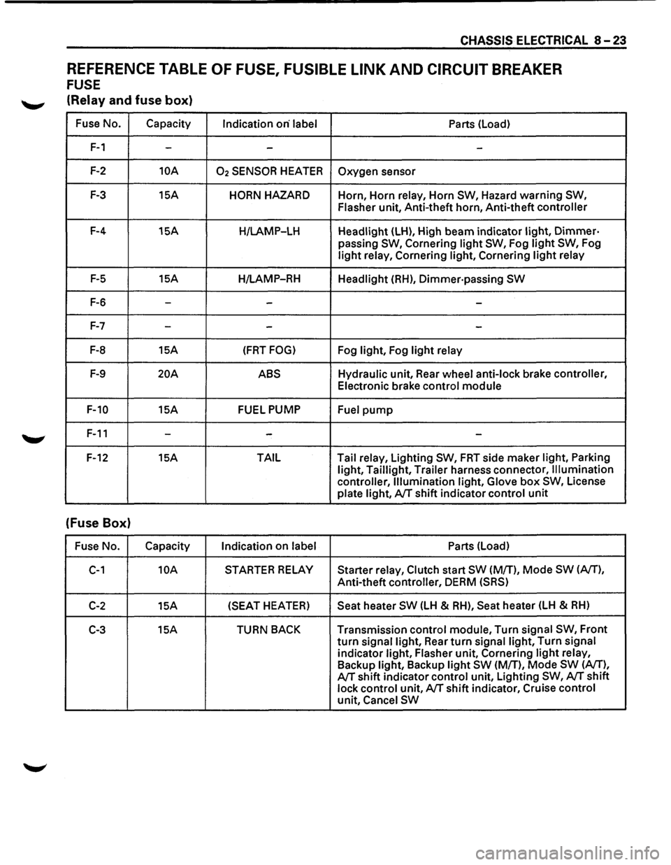
CHASSIS ELECTRICAL 8-23
REFERENCE TABLE OF FUSE, FUSIBLE LINK AND CIRCUIT BREAKER
FUSE
'--"' (Relay and fuse box)
Fuse No. Capacity
Indication on· label Parts (Load)
F-1 --
-
F-2 10A 02 SENSOR HEATER Oxygen sensor
F-3 15A HORN HAZARD Horn, Horn relay, Horn SW, Hazard warning SW,
Flasher
unit, Anti-theft horn, Anti-theft controller
F-4 15A
H/LAMP-LH Headlight (LH), High beam indicator light, Dimmer·
passing SW, Cornering light SW, Fog light SW, Fog
light relay, Cornering light, Cornering light relay
F-5 15A
H/LAMP-RH Headlight (RH), Dimmer·passing SW
F-6 ---
F-7 --
-
F-8 15A (FRT FOG) Fog light, Fog light relay
F-9 20A ABS Hydraulic unit, Rear wheel anti-lock brake controller,
Electronic brake control module
F-10 15A FUEL PUMP
Fuel pump
F-11 ---
F-12 15A TAIL Tail
relay, Lighting SW, FRT side maker light, Parking
light, Taillight, Trailer harness connector, Illumination
controller, Illumination light, Glove
box SW, License
plate light, A/T shift indicator control unit
(Fuse Box)
Fuse No. Capacity
Indication on label Parts (Load)
C-1 10A STARTER RELAY Starter relay, Clutch start SW (M/T), Mode SW (A/T),
Anti-theft controller, DERM (SRS)
C-2 15A (SEAT
HEATER) Seat heater SW (LH & RH), Seat heater (LH & RH)
C-3 15A TURN BACK Transmission control module, Turn signal SW, Front
turn signal light, Rear turn signal light, Turn signal
indicator light, Flasher unit, Cornering light relay,
Backup light, Backup light SW (M/T), Mode SW (A/T),
A/T shift indicator control unit, Lighting SW, A/T shift
lock control unit, A/T shift indicator, Cruise control
unit, Cancel SW
Page 1214 of 1928
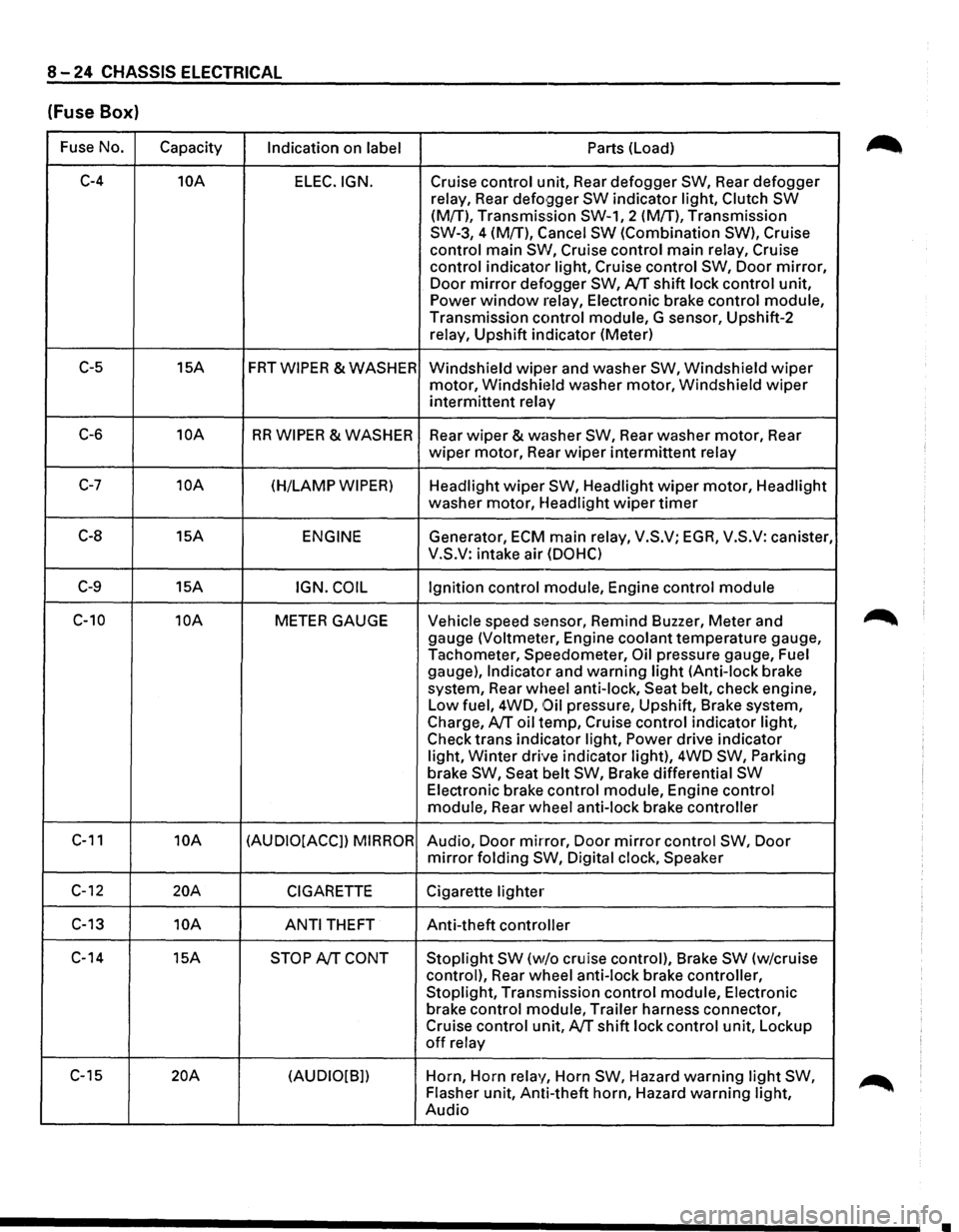
8-24 CHASSIS ELECTRICAL
(Fuse Box)
Fuse No.
Capacity Indication on label Parts (Load)
C-4 10A
ELEC.IGN. Cruise control unit, Rear defogger SW, Rear defogger
relay, Rear
defo9ger SW indicator light, Clutch SW
(M{T), Transmission SW-1, 2 (M!T), Transmission
SW-3, 4 (M{T), Cancel
SW (Combination SW), Cruise
control main
SW, Cruise control main relay, Cruise
control indicator light, Cruise control
SW, Door mirror,
Door mirror defogger SW, AfT shift lock control unit,
Power window relay, Electronic brake control module,
Transmission control module, G sensor, Upshift-2
relay, Upshift indicator (Meter)
C-5 15A FRTWIPER &WASHER
Windshield wipt~r and washer SW, Windshield wiper
motor, Windshit~ld washer motor, Windshield wiper
intermittent relay
C-6 10A RR WIPER & WASHER
Rear wiper & washer SW, Rear washer motor, Rear
wiper motor, Rear wiper intermittent relay
C-7 10A (H/LAMP WIPER) Headlight wiper SW, Headlight wiper motor, Headlight
washer motor, Headlight
wiper timer
C-8 15A ENGINE Generator, ECM main relay, V.S.V; EGA, V.S.V: canister,
V.S.V: intake air
(DOHC)
C-9 15A IGN. COIL Ignition control module, Engine control module
C-10 10A METER GAUGE Vehicle speed stmsor, Remind Buzzer, Meter and
gauge
(Voltmeter, Engine coolant temperature gauge,
Tachometer, Speedometer,
Oil pressure gauge, Fuel
gauge),
Indicator and warning light (Anti-lock brake
system, Rear wheel anti-lock, Seat belt, check engine,
Low fuel, 4WD,
Oil pressure, Upshift, Brake system,
Charge,
AfT oil temp, Cruise control indicator light,
Check trans indicator light,
Power drive indicator
light,
Winter drive indicator light), 4WD SW, Parking
brake SW, Seat belt SW, Brake differential SW
Electronic brake control module, Engine control
module, Rear wheel anti-lock brake controller
C-11 10A (AUDIO[ACCJ) MIRROR Audio, Door mirror, Door mirror control SW, Door
mirror folding SW, Digital clock, Speaker
C-12 20A CIGARETTE Cigarette lighter
C-13 10A
ANTI THEFT Anti-theft controller
C-14 15A
STOP AfT CONT Stoplight SW (w/o cruise control), Brake SW (w/cruise
control), Rear wheel anti-lock brake controller,
Stoplight, Transmission control module, Electronic
brake control module, Trailer harness connector,
Cruise control unit,
AfT shift lock control unit, Lockup
off relay
C-15
20A (AUDIO[B]) Horn,
Horn relay, Horn SW, Hazard warning light SW,
Flasher unit, Anti-theft horn, Hazard warning light,
Audio
•
Page 1217 of 1928
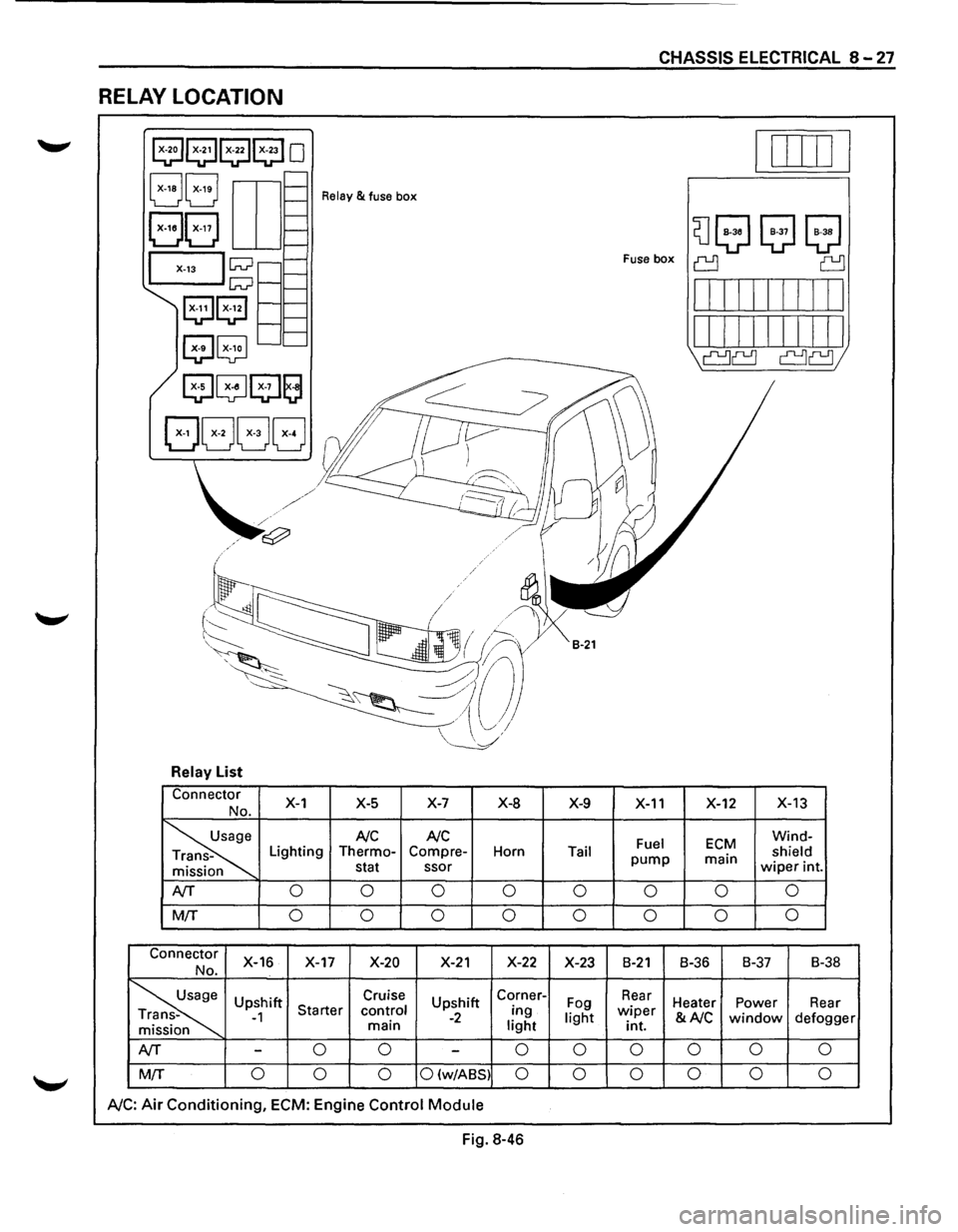
RELAY LOCATION
Relay & fuse box
Relay List
Connector X-1 X-5 X-7
X-8
No.
~
NC NC Lighting Thermo-Com pre-
Horn -stat ssor
n
NT 0 0 0 0
M(f 0 0 0
0
Connector
X-16 X-17 X-20 X-21 X-22
No.
~
Upshift Cruise Upshift Corner-
-1 Starter control -2 ing -main light n
NT -0 0 -0
M!f 0 0 0 0(w/A8S) 0
AJC: Air Conditioning, ECM: Engine Control Module
Fig. 8-46
B-21
X-9
Tail
0
0
X-23
Fog
light
0
0
CHASSIS ELECTRICAL 8-27
Fuse box
X-11
Fuel pump
0
0
8-21
II]]]J I
~8~8
c:J c:J
11111111111
111111
IIIII
BB a B
X-12 X-13
ECM Wind-
main shield wiper int.
0
0
0 0
8-36
8-37
8-38
Rear Heater Power Rear
wiper int. &NC window defogger
0
0 0
0
0 0 0
0